
Headframe


As headframe , pulley scaffold , pulley block or pulley chair is known a construction with the shaft of a mine or tunnel system is built from different materials and the recording of the pulleys is used. The headframe is differentiated from the headframe , in which the hoisting machine is usually located in the tower directly above the shaft. Unlike headframes, headframes can be exchanged after commissioning. Headframes and headframes are the most distinctive structures in a mine and they particularly shape the appearance of every mine.
history
As the mining industry in ever greater depths penetrated, the necessity of revealed Teufens of shafts leading to the promotion of the ore and manriding served. The hand reel was initially used as a hoisting machine . This was set up directly above the shaft and protected by a reel hoe . With the reaching of ever greater depths, the miners needed greater drive power and large sweeping wheels and gopel were constructed. For the first time, it was necessary to divert the conveyor ropes or chains. In his work De re metallica , Georgius Agricola describes these early winding machines in detail in words and pictures. However, the performance of these drives was not comparable to that of modern mines. Since all components were built lighter, a lightweight construction could also be used for the construction of the pulley frames. While the rope sheave frames were set up freely in the English and sometimes also in French mining, a different concept was pursued in German mining. Here the wooden rope sheaves were built around a hut or a shaft house to protect them from the weather .
The invention of the steam engine enabled further penetration into greater depths. The steam engines were generally set up at ground level next to the shaft. This type of installation was called an industrial truck to distinguish it from the installation above the shaft. Since the hoisting ropes must run in the shaft axis, they were on the pulleys deflected. Initially, masonry greenhouses were built for this purpose, which accommodated both the hoisting machine and the hanging bench. At the same time, wooden headframes were also used, and the wire ropes were protected from the weather by cladding. Both designs, however, were unable to cope with the stormy development of steam engines and the ever increasing depth of the shafts. If you wanted to guarantee the highest possible conveyor speeds and the necessary safety, you needed more free height above the hanging lawn bench and the scaffolding and houses therefore had to be built higher, which meant that they could no longer absorb the lateral forces.
Therefore, one went over to the construction of towers with massive buttresses ( Malakow tower ) and / or built a wooden or iron pulley chair inside the building. A tower absorbs the lateral forces through its own weight. A sheave frame absorbs these forces by means of a strut construction that is aligned in the direction of the resulting force from the axis between the hoisting machine and the sheaves on the one hand and the weight of the hoisting cages hanging in the shaft on the other. The first steel headframe was erected in 1864 on a mine in the French city of Hainaut. From the middle of the second half of the 19th century, more and more free-standing steel structures came into use as strut frames. The closed Malakow Tower or the greenhouse was mostly only used when the weather shafts were extended, as this design minimizes weather losses. Countless headframes later shaped the industrial region of the Ruhr area. Here mainly were Tomson trestles , strut frames and double trestle scaffolding erected.
Basics
The headframe has two main tasks. On the one hand, the conveyor frame must serve as a support frame for the sheaves and, on the other hand, the conveyor frame should form a corresponding guide for the conveyor cage or for the conveyor vessel outside the shaft. When constructing a headframe, the required height and the type of support for the sheaves must be taken into account. The height of a headframe depends on several factors. An essential factor is the free height, i.e. the distance between the intermediate gear when the conveyed goods carrier is in the highest operating position, and the impact carrier . This distance is stipulated by the mining authorities as the minimum distance. It is ten meters for larger cable cars and three meters for smaller cable cars. This distance is necessary so that there is still a sufficient safety distance between the suspension bench and the pulleys in the event of overdoing . The safety distance is often chosen to be larger and is up to 25 meters for individual systems. Within the safety distance that serves as an overdrive path for the conveyed goods carrier in the event of an overdrive, the conveyor is braked by the safety brake of the hoisting machine and the anti-overdrive device to such an extent that it comes to a standstill as far as possible in front of the impact carrier. Another factor that has an influence on the height of the headframe is the position of the suspended bench. Here, the local location of the processing operations such as the screening plant and processing plant must be taken into account. Furthermore, the height of the headframe must be dimensioned in such a way that there is sufficient height for hanging long materials such as B. Pipes, long pit wood or rails remains. If the hanging lawn bench is used as a conveyor stop instead of a hanging bench, the conveyor frame can be built correspondingly lower. Ultimately, the height of the goods carrier also has a significant influence on the height of the headframe.
The sheaves can be stored in the conveyor frame, depending on the position of the goods carriers in relation to one another and in relation to the direction of the cable carrier axis , above or below one another. If reels or drums are used as cable carriers in the hoisting machine , the cable sheaves are stored next to one another in the conveyor frame. The reason for this is the lateral deflection of the rope, which occurs due to the width of the rope carrier. To reduce this rope deflection, a lateral distance between the sheaves is necessary. If a traction sheave is used as the rope carrier , it is more advantageous to mount the sheaves on top of one another. This arrangement of the sheaves makes the headframe narrower, but also higher due to the dimensions of the sheaves. However, the superposed pulleys result in a smaller wrap angle on the traction sheave. When building a conveyor frame, the tensile forces that occur must also be taken into account and the frame must be designed accordingly. It should also be taken into account that the entire rope pressure acting on the sheave must be absorbed by the headframe. For safety reasons, headframes must be equipped with a standardized lightning protection system.
construction materials
Different building materials were used for the construction of headframes and headframes. Wood, wood combined with masonry, steel, cast iron or reinforced concrete were used for construction. The oldest building material was wood because it was cheap to get and easy to work with. The individual pieces of wood are mortised together or screwed together to form a frame using iron screws and plates. However, these scaffolds only have a relatively short lifespan, which is between 15 and 18 years depending on the climatic conditions. In the particularly harsh climate, the service life is significantly shorter. It is six years for untreated softwood and ten years for oak. Unshod logs are better than studded ones. In order to increase the service life, the woods must be given a protective coating, which consists of either tar or special impregnating agents. This protective coating is particularly necessary in the case of extending shafts, as the ascending downward weather is usually damp and warm, which promotes rapid decay of the wood. The flammability of the wood is also disadvantageous if it is not impregnated in a fire-proof manner. Ultimately, wooden headframes are only suitable for lower loads. They are therefore only suitable for smaller systems. Another disadvantage of wood is that wood that is twelve meters and longer is rarely available. In order to still achieve the required height of the sheaves, the wooden headframe is placed on foundation walls several meters high. Steel headframes are more expensive, but they have clear advantages over wooden frames. They have the advantage that they have a relatively low weight. In addition, they are significantly less prone to repairs and malfunctions. Further advantages of steel scaffolding are their fire safety, the longer service life than wooden scaffolding, and they can be built significantly higher than wooden conveyor scaffolding. However, it is disadvantageous that, due to their low weight, they only have low side forces, as they occur e.g. B. can arise by cable pull and must be supported by struts. Cast iron was used as a building material for headframes only to a limited extent, mainly in the English mining industry. The disadvantage of this building material is that it is very brittle and therefore breaks quickly with abrupt load changes. Reinforced concrete is mainly used for the construction of headframes. Reinforced concrete is poorly suited for the construction of strut scaffolding. Nevertheless, headframes made of reinforced concrete were also built and operated. The disadvantage of reinforced concrete is its high weight and lack of flexibility in the event of vibrations and subsidence or other changes. Through additional measures, such as B. internal reinforcements, these disadvantages can be partially offset.
Basic construction method
Basically, a headframe consists of the support frame, the guide frame and the sheave platform . The shoring consists of supporting and bracing structural elements. The guide frame, also known as the air shaft, is used to accommodate the shaft guide above the shaft mouth. If possible, it should be installed in such a way that it is not used to absorb the lateral tensile forces. Reasons for this are, on the one hand, that the guide frame is exposed to elastic changes in shape due to the tensile forces and, on the other hand, that it would pass these tensile forces on to the shaft lining. However, there are also constructions in which there is no clear separation between the support frame and the guide frame. In these headframes, the support frame and the guide frame together form the support system. The sheave platform is used to hold the sheaves.
Headframes are divided into three classes, the support system, the support system and the combined support and support system. Which system is ultimately chosen depends on the respective production process, the respective storage facility and the operational and machine requirements. The pure carrier system consists of either two or four carriers that are connected to one another. These carriers are used to support the pulley bearings with the pulleys stored in them. The guide frame is enclosed up to the top by a tower made of solid masonry with a wall thickness of up to 1.5 meters. This system is therefore also known as the carrier system in brick towers. The ends of the beams are mounted in the masonry of the tower.
The trestle system distinguishes between two-, three- and four-legged trestles. The name of the trestle depends on how many individual supports it consists of. The first wooden trestle scaffolding could already be statically calculated at the beginning of the 19th century. The two-legged and three-legged trestles are braced by struts in the direction of pull towards the hoisting machine. Each strut consists of two or three interconnected individual supports (legs). The struts have the task of absorbing the cable pull from the hoisting machine. If the shoring is reinforced by two additional vertical supports, it is called a four-legged trestle. The trestle system has decisive advantages over the carrier system. All trestle systems do not require any shaft towers, and trestle systems can also be manufactured in a shorter time and are also more cost-effective. The disadvantage of this system is that a special protective roof must be attached over the pulleys. A combination of a masonry shaft tower and free-standing scaffolding are headframes in which the enclosing walls of the shaft tower only extend to the suspended bank. The surrounding walls serve as supports for the headframe, which consists of four trestle legs. With the combined girder and trestle system, the girders on which the sheaves are stored are also stored in the masonry of the shaft tower, but are also supported from below by columns or struts, so that the girder and trestle system are combined in one system.
Designs
Simple pulley frames

The simple sheave frames, as they were required for conveying with the Göpel, have little resemblance to modern conveyor frames. The base of these pulley frames was formed by four main posts sunk into the ground. The front posts were positioned in such a way that the pulleys were centered above the shaft pulley . The four main posts were connected by three rows of mortised beams, which were connected to two main posts parallel to the long shaft joint. The bearings for the rope sheaves were mounted on these pieces of wood, known as bars. These so-called weighing sticks were attached to the bolts using nailed wooden blocks or iron straps. Care must be taken to ensure that the direction of the sheaves is aligned so that it corresponds to the direction of the rope runs. The two sheaves must each be attached at different heights so that the rope can be wound onto the rope basket accordingly. In order to protect the sheave structure from the weather, it was usually surrounded by a building. This building often had a barn-like shape. In addition to these pulley scaffolding, there were also simple scaffolding, which consisted of three main posts that were connected to one another by means of crossbars. These scaffolds, known as tripods , were often used on small mines.
Pyramid framework
A pyramid framework is built according to the carrier system. Either wood or steel is used as building material. However, wood is only used in shafts with a lower depth, in which only smaller loads have to be conveyed. Another application is the use as sinking scaffolding. The framework has the shape of a truncated pyramid. The base of the scaffolding is formed by four strong corner pillars made of wood or steel, which are aligned so that they approach upwards. Each of these corner pillars stands on a brick foundation . They are connected to the respective foundation with cast iron shoes and anchors. The corner pillars are connected to one another by horizontal crossbars. Because of their general construction, pyramid frames have a relatively small footprint. As a result, pyramid frames can tilt to the side due to lateral tensile forces that only act on one side. To prevent this, the framework can be reinforced so that it has the greatest possible weight. This tendency to tilt can also be prevented by attaching side struts to the scaffolding in the pulling direction. This design is known as a braced pyramid frame. Another possibility to improve stability is to change the inclination of the corner pillars or to enlarge the base area. The advantage of the pyramid scaffolding over other scaffolding is that the air shaft is not burdened by the sheave platform , as it only serves to guide the goods carriers.
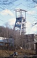
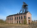
Strut or trestle frames
These scaffolds were constructed in the mountain areas in different shapes and with different building materials. A basic distinction is made in the construction method between German and English strut frames. The individual headframes are built either in a half-timbered construction, in solid wall construction or in hollow box form. First, riveted steel framework scaffolding was built, later so-called full wall scaffolding and later still scaffolding made of box profiles. This primarily reflects the development of steel processing. Depending on the type of bracing, a distinction is made between single strut scaffolding, double strut scaffolding and tower scaffolding.
Examples of strut frames

Headframe of the former Monopol colliery in Kamen

Strut frame of the Holland colliery

Strut frames of the Auguste Victoria colliery in Marl .

Headframe shaft 15 IIb in Schlema
Headframe of shaft 371 in Hartenstein

Headframe of the tonnage Türk shaft in Zschorlau

Headframe of the Grimberg mine
Headframe of the Reichen Zeche in Freiberg

Concrete strut scaffolding Prokop shaft in Příbram, Czech Republic

Zeche Zollern
shafts 2 and 4
Strut frame of the Arno-Lippmann-Schacht (1952-1963) in Altenberg , Saxony


_2006-11-08.jpg)

.jpg)

Brace frames
English trestle
The English trestle frame, also known as a four-legged trestle or as an English strut frame, has a relatively simple construction that is statically simple. Its static calculation is based on the parallelogram of forces. It consists of vertical supports and struts mounted towards the hoist. In order to stiffen this scaffolding, horizontal bars are installed at certain distances between the supports and the struts. The vertical supports take up the vertical loads and the struts take up the horizontal forces acting in the direction of the hoisting machine. The sheave platform is attached to the scaffold head in such a way that the sheaves are at the intersection between the support and the struts. With this construction, the load of the sheave platform is not transferred to the guide frame. In addition, there is no bending deformation on the bracket, as only compressive forces act on the bracket. Since the guide frame is not loaded by the load of the sheave platform, it can be constructed much more easily than with the German strut frames. It is secured against falling over by stiffening it against the sheave frame. A headframe construction that is very similar to the English trestle is the Tomson trestle .
Examples of scaffolding

English trestle for the Ottiliae shaft from 1876 in Clausthal-Zellerfeld , Germany's oldest steel winding tower.
Tomson-Bock headframe of the Gneisenau colliery


German strut framework
The German strut frame is a further development of the English trestle. It has no vertical supports, the struts are connected to the guide frame by means of horizontal beams and form the base frame for the sheave platform. The pulleys are shifted on this construction. On the one hand, with this scaffold, the guide scaffold must support the sheave platform. In addition to this weight, the guide frame must also support the weight of the struts. The guide frame is thus used to transfer the entire vertical load. Since the entire weight has an effect on the support of the guide frame, it must be equipped accordingly. To store the guide frame, strong longitudinal and transverse girders are built into the shaft head underneath the hanging lawn bench. The struts are designed in the shape of a fish belly, the individual legs are stiffened with cross bars for stiffening.
Two-strut frame
The two-strut frame, also known as the double-strut frame, was developed to work in one shaft with two parallel conveyors. In this type of shaft hoisting system, the hoisting machines are set up on opposite sides of the headframe. Two-strut frames are two-storey, with the pulleys on each side being stacked. Due to this arrangement of the sheaves, there is no lateral rope deflection when the traction sheave is conveyed. Since the inclined cable to the hoisting machine, due to the hoisting machines set up opposite, also acts on both sides, both sides must also be supported with struts. The two-strut structure is practically a duplication of the two-storey strut structure. The scaffolding is constructed in such a way that the struts and the girders of the sheave platform form the supporting structure. The guide frame stands freely upwards and is connected to the foundation via strong anchoring. Since the guide frame does not bear any loads from the sheave platform, it is only constructed relatively weakly.
Examples of two-strut frames

Steel box Doppelbock colliery Haus Aden on the Datteln-Hamm Canal

Doppelbock over a shaft of the Pluto colliery in Herne-Wanne

Doppelbock Shaft 12 Zeche Zollverein

Doppelbock of the former shaft 403 ( mining company Drosen )

Doppelbock of the graphite mine Kropfmühl


Tower frame
Since the rope sheaves are stored lying on top of each other in double strut frames and there is therefore no lateral rope deflection in the case of traction sheave conveyor systems, the two hoisting machines can also be installed very close to the shaft. As a result of this arrangement of the hoisting machines, the ropes run approximately perpendicularly from the traction sheave to the sheaves . This has the consequence that the horizontal cable components are only available to a small extent. For this reason, the lateral struts, which are subject to bending, can be completely omitted in this construction. Additional compression and tension rods have to be integrated into the framework to stiffen the framework. Nevertheless, the tower frame is significantly lighter than a strut frame of the same strength. The advantages of tower scaffolding are the large space savings and the low knocking of the hoisting ropes .
Examples of tower scaffolding

Tower frame of the Gneisenau colliery

Tower scaffolding of the Walsum colliery


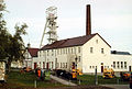
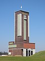
Headframes

Headframes are built in steel or concrete framework construction, or also in solid concrete construction using sliding formwork. The hoisting machine is located in the upper part of the tower directly above the shaft mouth. Since the hoisting machine is located vertically above the shaft in this design, there is no lateral cable pull and the supporting struts are omitted. However, it is disadvantageous that the hoisting machine is more difficult to access. If the machine platform (the top floor of the tower) protrudes over the walls on two opposite sides, one speaks of hammer head towers due to the characteristic appearance . Typical is a design for a four-column conveyance with four rubble side by side, in which two conveyors are arranged symmetrically in the tower head. When using a hoisting machine with a traction sheave, the installation of the sheaves is not necessary. However, a deflection disk, also called a guide disk, must be installed for every conveyance. These ensure that the hoisting rope is deflected to the center of the basket. Drum hoisting machines are poorly suited for hoisting towers, as the hoisting rope moves over the drum when it is driven and the hoisting rope is therefore not directed to the center of the cage due to the short distance between the drum and the deflection disc. The installation of the hoisting machine in the tower head is also only feasible with electric hoisting machines, since excessive vibrations are transmitted to the structural parts in steam engines. If headframes are more than 25 meters above the suspended bench, they must be provided with an elevator.
Application examples headframes
There have been repeated attempts to set up the hoisting machine above the shaft, as a pulley could be omitted and the driving rope was once less deflected. Already since 1860 there was a wooden headframe in half-timbered construction with a steam hoisting machine in lignite mining on the Karl Grube. However, the shaft was only shallow. At greater depths, the winding towers were unsuitable for setting up the heavy drum winding machines. In the 1870s, the first winding tower was put into operation at the Hanover colliery . The hoisting machine was equipped with a traction sheave, but had a steam drive. In the following years, however, this concept of setting up the hoisting machine above the shaft in the tower was abandoned, as the towers could not withstand the strong vibrations caused by the steam hoisting machines. Only with the introduction of the electric hoisting machine could this problem be solved satisfactorily. The first German shaft with such a system was the new Heinrich shaft of the von Arnim'schen coal works in Planitz near Zwickau (1899).
“An electrically powered hoisting machine of 30 horsepower was installed directly above the hoist shaft and put into operation in June 1899. The hoisting machine lifts 600 kg payload in one trip and is able to move 400 carts = 200 t in 10 hours from a depth of 107 m. The electric drive has proven itself well and has not given rise to any circumstances. The maneuverability is just as great and the operation is even easier than with the steam hoisting machine. "
The machine of the new Alexanderschacht was not a Koepe conveyor , but a drum conveyor , as can be seen on an old photo. There is therefore the possibility that the machine of the new Heinrich shaft was also not a Koep machine, however, due to the poor source situation, there has so far been neither positive nor negative evidence. In any case, however, this hoisting machine was the first electric hoisting machine in Germany to be installed directly above the shaft. It was not uncommon for these constructions to be used one after the other on a shaft. For the older mines in the Ruhr area in particular, it was often the case that a hothouse was replaced by a Malakow tower, later a steel strut frame was attached to it and, in the last phase before the colliery died out, this was crowned with a winding tower. A typical example was the Pörtingsiepen colliery .
Examples of winding towers
Headframe of the Koenigsborn colliery in Bönen

Headframe of the Karl Liebknecht shaft in Oelsnitz / Erzgeb.

Concrete headframe in stilt construction, shaft February 25 in Bohutin (Příbram), Czech Republic

Shaft IV of the Camphausen mine, Saarland

Morgensternschacht II greenhouse in Reinsdorf (Zwickau coal region) for extraction, driving and suction ventilation, Saxony

Concrete headframe (built before 1968, closed 1996) of the Garmica mine in Měděnec (Kupferberg), Czech Republic


.jpg)


Industrial monuments
Striking winding towers and scaffolding can be seen today as industrial monuments, especially in the Ruhr area . The former double-headed headframe of the Germania colliery in Dortmund was dismantled after the plant was shut down and erected as a new landmark above the German Mining Museum in Bochum . The scaffolding was designed by Fritz Schupp .
Individual evidence
- ^ A b c d e f g Walter Bischoff , Heinz Bramann, Westfälische Berggewerkschaftskasse Bochum: The small mining dictionary. 7th edition. Glückauf Verlag, Essen 1988, ISBN 3-7739-0501-7 .
- ^ Carl Friedrich Alexander Hartmann: The advances in hard coal mining in recent times. Or the current point of view of exploration - extraction and extraction of mineral fuels, in addition to a brief development of the latest quantitative hard coal and lignite - production, published by Julius Springer, Berlin 1859, pp. 243, 244.
- ^ A b Emil Treptow, F. Wüst, W. Borchers: Mining and metallurgy. Illustrated for other circles, publishing house and printing by Otto Spamer, Leipzig 1900, p. 111.
- ^ A b c Emil Treptow: Mining including quarrying and precious stone extraction. Publishing and printing by Otto Spamer, Leipzig 1900, p. 111.
- ^ A b Franz Rziha: Textbook of the entire art of tunneling. First volume, published by Ernst & Korn, Berlin 1867, pp. 310, 311, 329, 333–336.
- ↑ a b c d e f g h i j k l m n o p q Carl Hellmut Fritzsche: Textbook of mining science. First volume, 10th edition, Springer Verlag, Berlin / Göttingen / Heidelberg 1961, pp. 515-520.
- ↑ a b c d Horst Roschlau, Wolfram Heintze: Bergmaschinentechnik. VEB German publishing house for basic industry, Leipzig 1977, pp. 245–246.
- ↑ a b c d e f g h i j k l m n o p q r s t Rainer Slotta: The role of iron in the mining architecture of the second half of the 19th century with special consideration of the headframes and headframes . In: iron architecture. ICOMOS, German National Committee (ed.), 5-9. October 1981, pp. 14-23.
- ↑ a b c d Wilhelm Hermann, Gertrude Hermann: The old collieries on the Ruhr. 6th edition, updated by Christiane Syré and Hans-Curt Köster. Langewiesche Nachf. Köster, Königstein im Taunus 2007, ISBN 3-7845-6994-3 , pp. 4–128.
- ^ A b Wilfried Ließmann : Historical mining in the Harz. 3rd edition, Springer Verlag, Berlin and Heidelberg 2010, ISBN 978-3-540-31327-4 , pp. 56, 81.
- ^ Georg Agricola: Twelve books on mining and metallurgy. In commission VDI-Verlag GmbH, Berlin.
- ↑ a b c d e f g h i j k A. Eichenauer: The pulley frames of the mine conveyor systems. Baumgärtner's Buchhandlung, Leipzig 1877, pp. 1–22.
- ^ Julius Ritter von Hauer: The conveyors of the mines. Second increased and partly revised edition, published by Arthur Felix, Leipzig 1874, pp. 254–261.
- ^ A b c Association for Mining Interests in the Upper Mining District Dortmund: The development of the Lower Rhine-Westphalian hard coal mining in the second half of the 19th century. Volume VIII: Disposition of the daytime systems-steam generation-central condensation-air compressors-electrical central units. Springer Verlag, Heidelberg / Berlin 1905, pp. 4, 5, 18–21, 30, 31.
- ^ A b c Fritz Schmidt: The basics of the conveyor machine system. Springer-Verlag Berlin Heidelberg GmbH, Berlin Heidelberg 1923, pp. 9-17.
- ↑ a b c d e f g h i j k l m n o p q r s t Walter Buschmann: Collieries and coking plants in the Rhenish coal industry, Aachen district and the western Ruhr area. Gebr. Mann Verlag, Berlin 1998, ISBN 3-7861-1963-5 , pp. 88-100, 128-160.
- ↑ a b c District Administrator Recklinghausen (ed.): Contributions to the 132-year history of hard coal mining in Recklinghausen. Kreishausdruck, Recklinghausen 2001, pp. 65-68.
- ↑ a b c d Hans-Stefan Bolz: Hans Poelzig and the modern factory building. Industriebauten 1906–1934, inaugural dissertation to obtain a doctorate from the Philosophical Faculty of the Rheinische Friedrich-Wilhelms_Universität zu Bonn, Bonn 2008, Volume I, pp. 47–49.
- ↑ a b c d e f g h i j k l Fritz Heise, Fritz Herbst: Textbook of mining studies with a special focus on hard coal mining. Second volume, fifth increased and improved edition, published by Julius Springer, Berlin 1932, pp. 674–679.
- ^ A b c d e Mathias Küster: Steel structures in industrial construction in the historical development. Bachelor thesis at the University of Applied Sciences Neubrandenburg, Faculty of Civil Engineering, Neubrandenburg 2010, pp. 27, 28.
- ↑ a b c Hans Bansen (Ed.): The mining machines . Third Volume, The Shaft Carriers. Published by Julius Springer, Berlin 1913, pp. 3-6.
- ↑ Wilhelm Breucker, Ernst Ulrich: Better protection in the event of overdoing in a shaft hoisting system. In: The WBK rope testing center provides information. WBL-Seilprüfstelle (Ed.), No. I, 11, July 1988.
- ↑ a b Technical requirements for shaft and inclined conveyor systems (TAS). Verlag Hermann Bellmann, Dortmund 2005, sheet 1/1.
- ^ Julius, Ritter von Hauer: The conveyors of the mines. Verlag von Arthur Felix, Leipzig 1871, pp. 211–213.
- ↑ a b c d e f g h i j k l m n o p q r s t u v Hans Bansen (Ed.): Die Bergwerkmaschinen . Fourth volume, The shaft production. Published by Julius Springer, Berlin 1913, pp. 294-318.
- ^ Julius Ritter von Hauer: The conveyors of the mines. Third increased edition, published by Arthur Felix, Leipzig 1885, pp. 413–421.
- ^ Emil Stöhr, Emil Treptow: Basics of mining science including processing. Spielhagen & Schurich publishing house, Vienna 1892, pp. 205–206.
- ↑ a b c Albert Serlo: Guide to mining science. Second volume, fourth revised edition and supplemented up to the most recent time, published by Julius Springer, Berlin 1884, pp. 218–220.
- ^ F. Kögler: Newer headframes and headframes made of reinforced concrete. In: Glückauf, Berg- und Hüttenmännische magazine. Association for mining interests in the Oberbergamtsiertel Dortmund (ed.), No. 6, 63rd year, February 5, 1927, pp. 185–193.
- ^ P. Walter: The new headframe building Kaiser - Wilhelm - shaft of the Hohenzollern pit. In: Steel construction. Supplement to the journal Die Bautechnik, specialist journal for the entire construction industry, issue 2, 1st year, Berlin, April 20, 1923, pp. 15-19.
- ↑ Mautner: Newer reinforced concrete - constructions in the field of mining. In: Deutsche Bauzeitung. Communication on cement, concrete and reinforced concrete construction, with the participation of the Association of German Portland Cement Manufacturers and the German Concrete Association, No. 10, Volume VIII, 1911, pp. 75–80.
- ^ F. Kögler: headframes and headframes in reinforced concrete. In: Glückauf, Berg- und Hüttenmännische magazine. Association for mining interests in the Oberbergamtsgebiet Dortmund (ed.), No. 40, 57th year, October 1, 1921, pp. 957–960.
- ^ A b Gustav Köhler: Textbook of mining history. Second improved edition, published by Wilhelm Engelmann, Leipzig 1887, pp. 414, 415.
- ↑ a b c d C. Erdmann: Iron winding towers. In: Journal of the Association of German Engineers. Commissions-Verlag by Rudolph Gaertner, seventeenth year, Volume XVII, Berlin 1873, pp. 400–404.
- ↑ a b c Fritz Heise, Fritz Herbst: Brief Guide to Mining Studies. Third improved edition, published by Julius Springer, Berlin 1932, pp. 216, 217.
- ^ Gustav Köhler: Textbook of mining science. Sixth improved edition, published by Wilhelm Engelmann, Leipzig 1903, pp. 466–468.
- ^ A b Carl Johann Bernhard Karsten (ed.): Archives for mining and metallurgy. Seventh volume, printed and published by G. Reimer, Berlin 1823, pp. 459, 460.
- ^ Förderverein Rammelsberger Bergbaumuseum Goslar eV (Hrsg.): Rammelsberg daily facilities. Self-published by the Förderverein, Druck Papierflieger Clausthal-Zellerfeld, Goslar 2008, pp. 15–17.
- ↑ Erik Zimmermann: Black Gold in the Ruhr Valley . The history of Werden mining, Verlagsgruppe Beleke, Nobel Verlag GmbH, Essen 1999, ISBN 3-922785-57-3 , p. 89.
- ↑ Heinz M. Hiersig (Ed.): VDI-Lexikon Maschinenbau. VDI-Verlag GmbH, Düsseldorf 1995, ISBN 978-3540-62133-1 .
- ^ F. Kögler: winding towers in reinforced concrete on "United Field" in Hohndorf, Erzgebirge. In: Der Bauingenieur, 7th year, issue 23, June 4, 1926, pp. 453–457.
- ^ A b H. Hoffmann: Textbook of mining machines (power and work machines). Springer Verlag GmbH, Berlin / Heidelberg 1926, p. 167
- ^ Yearbook for mining and metallurgy in the Kingdom of Saxony. Year 1900 ( Memento from November 9, 2013 in the Internet Archive ) (PDF)
- ^ Coal mining in the Zwickau area , Zwickau Coal Mining Association, Förster & Borries Zwickau, 2000, ISBN 3-00-006207-6
Web links
- Overview of the construction types of headframes in the Ruhr area (accessed on January 7, 2019)
- on the first headframe in box construction in North Rhine-Westphalia (Zeche Niederberg 4), article and (historical) photos (accessed on January 7, 2019)