
Truss


A truss is a framework whose bars are only stressed by normal force and "whose ends are connected to one another at the nodes ". A compartment is a two-dimensional polygon that is spanned by bars. Trusses usually consist mainly of triangles. The term half-timbered is probably derived from the Middle High German vach or fah for area and mesh divided into fields .

Articulated node connections are one of several characteristics of the so-called ideal truss , which is often mentioned in the literature as a central property of the truss. Real trusses are usually made with flexible rods that can be modeled approximately as articulated nodes. Frameworks with rigid nodes are not frameworks in the strict sense.
A truss support is a generally horizontally extending and narrow relative to its length and slender support member. The bars running through the top and bottom are called the top and bottom chords . The bars of a lattice girder are closer than those of a lattice girder , giving the impression of a lattice.
Applications
Construction

Structures made from trusses generally have a low dead weight in relation to other common construction methods for their load-bearing capacity. Their large volume can have a disadvantage (example: truss bridges with a strong visual appearance). Your earthquake security is high.
Spatial building trusses are available as facades , roofs (also canopies and hall roofs) and domes . Further applications are truss bridges , cranes ( gantry cranes , crane bridges, tower cranes , luffing cranes, etc.), masts ( high-voltage masts , catenary masts , telephone masts , wind power masts ) and observation towers .

- Construction trusses, schematic

For bridges and roofs

For roofs ( Polonceau binder)

For roofs and halls (with masts)


vehicle construction

In automobile and motorcycle construction , three-dimensional frameworks are used as so-called lattice frames for chassis . However, they often do not only contain bar triangles, which is particularly true of motorcycle frames. These are mixed forms of general, rigid framework and framework.
Historically, the entire fuselage of airplanes, including the wings, was made of (wood) framework and covered, for example in the DFS 230 , a cargo glider with an aircraft fuselage made of a welded tubular steel framework with fabric covering. Also rigid airships were - in contrast to the inflated inflatable airships built with timber-supporting structures -.
Ideal and real framework
The investigation of the serviceability (strength and elastic deformation) of trusses is carried out with the help of strength and deformation theory , which is referred to as structural analysis in its application to supporting structures . In strength and deformation studies, simplifying, i.e. H. idealizing assumptions about reality. The pair of terms ideal truss / real truss , which is common in structural engineering, relates in particular to the assumptions about the stiffness of the nodes. Replacing their relatively low rigidity with flexibility is an idealization.
Idealizations
- A low bending stiffness of the rod connections is neglected in favor of articulated connections.
- The fact that the truss rods are never exactly straight is neglected.
- The fact that the axes (and thus also the lines of action of the member normal forces) never intersect exactly at a node is neglected.
- External loads that do not act on knots (not knot forces ) are neglected. It is common to neglect the weight of the bars. Loads acting directly on bars (weight forces from road slabs, wind forces, etc.), however, must i. d. Usually be observed.
In summary, it follows that only normal forces in the members are taken into account, bending moments, shear forces and torsional moments are neglected.
Real framework
The above Idealizations (especially not all of them together) are made in practice and, for security reasons, may not always be carried out. The calculation effort is correspondingly higher. So are z. B. to determine so-called secondary stresses (in addition to normal stresses) and to evaluate them for the permissible material stresses and for the permissible deformation of the framework.
Investigation and calculation methods
The methods given below assume an ideal framework.
Static determinacy: counting criteria
The fact that trusses are statically determined is a question that must first be answered in their investigation. In principle, it can only be provided with joints (instead of rigid nodes), i.e. only with ideal frameworks.
A statically under-determined framework is ruled out because it would be mobile on its foundations or within itself. Statically over-determined trusses have too many bars, which contradicts the principle of lightweight construction . However, they are stable and only have the disadvantage that the examination effort increases. Thermal expansions and dislocations of the foundations can cause secondary (with regard to actual use additional) stresses.
The question of whether a truss is statically determined is answered in principle by evaluating the equilibrium conditions (sum of all forces or torques is zero). The so-called counting criteria were developed from them as a simplified method of determination. It only provides a number that says how often a system is underdetermined minus the degrees of freedom. Often static systems either have degrees of freedom or are statically overdetermined, or are statically determined, there and only there the formula can be used as to how many degrees of freedom / overdetermined a system is. The formula does not say whether it is applicable or not, so it should only be used as a control. The counting criteria are only a necessary, but not sufficient, condition for the verification of static determinacy.
A determination can be made with so-called degradation or construction criteria (what happens if a rod is removed or added?). The sure answer also results from working with the equilibrium conditions.


The following formula is used for flat trusses:

Here is
- the sum of the movement possibilities prevented in the support swivel joints ( values of the supports),
- the number of bars,
- the number of swivel joints (supports + connections).


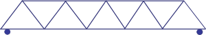
Example: truss shown on the right
- ⇐ the framework shown opposite is statically determined.

The following formula is used for spatial trusses:

Calculation method for trusses
Node method (round cut method)
With the node point method, the bar forces can be determined by setting up a system of equations . For each node of a 2-D framework, the maximum two linearly independent equilibrium conditions - z. B. the sum of the forces in the x and y direction must be zero - determined. This results in a system of equations that can be solved if the framework is statically determined.
In the three-dimensional case, a maximum of three linearly independent equations can be set up.
Ritter's cutting method
The Rittersche cutting method is used to calculate the normal forces in the truss. This means that a maximum of three bar forces can be calculated per section in two dimensions or a maximum of six bar forces in three dimensions.
Exchange of staff
The Hennebergsche staff exchange process is conducted at not easy applied trusses.
Cremonaplan
In statically determined frameworks, the Cremonaplan is used to graphically determine the bar forces.
Truss names and types of planar trusses

Half-timbered association with St. Andrew's crosses

Half-timbered with K-bracing

Stand framework
Strut framework

Strut framework with posts

The distortion (displacement) of the squares in the diamond framework is prevented by integrating them into the overall construction.

Lattice girders are not trusses in the strict sense, as the bars run through at the junctions. The nodes are therefore stiff in the direction of the rod, while they act as joints across the direction of the rod.


Space framework
Space frames are different from spatial trusses and frames in that they are mutually stable even without bending-resistant compounds of the rods. You thus comply with the Education Act for spatial frameworks. The spatiality of the trusses can be done either by arranging the bars in several layers ( lower chord , diagonals, upper chord ), or / and by arranging the bars in space. In the first case, a flat spatial framework is created, in the second a stepped or curved spatial framework, which in special cases (e.g. with a dome ) can also be single-layer. The geodesic dome is a classic example of the spatial, curved, but in principle flat framework .
The bars are generally connected with knot parts that can be solid (spheres, cylinders) or loosened (discs).

Spatial structure

Computer graphics of a Mero framework knot

View into the RFW of Air Shard Daniel Libeskind's Imperial War Museum North
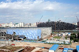
Irregular space framework of the Water Cube in Beijing
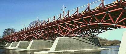
Space framework of the Thalkirchner Bridge in Munich


geometry
The geometry of the rod arrangement plays an essential role in the design of spatial frameworks. The level and stepped spatial frameworks can be derived from a combination (composition) of tetrahedron and (half) octahedron , more rarely from the hexahedron ( cube ). The space frameworks for domes can be derived from the dodecahedron and icosahedron . The five named polyhedra form the Platonic solids .
The geometry of space frameworks on freeform surfaces , especially those on NURBS (Non Uniform Rational B-Spline surfaces), requires the use of special CAD programs that allow mesh generation on these surfaces.
Planning and manufacturing
Any configuration can be implemented through computer-assisted planning and production . Nevertheless, the orientation of the connecting nodes is a particular problem in order to minimize the node size and milling work, especially in the case of free-form surfaces with a directly lying glass covering.
material


Practically any building material ( wood , steel , aluminum , stainless steel , carbon fiber reinforced plastic and, in rare cases, concrete ) can be used for trusses , or combinations thereof. Round, curved and (poly) angular profiles are possible, as well as any combination of these. In the case of metals, rolled products such as B. sheets , profile beams (I, L, U, T, Z profiles) and other shapes are used.
Web links
- Space trusses with reference objects. In: arch INFORM .
- Framework panel made of laminated veneer lumber
Notes and individual references
- ^ Fritz Stüssi : Baustatik I. Birkhäuser Verlag , 1971, p. 116.
- ↑ Mang , Hofstetter: strength theory. Springer, 2013, p. 156: "A framework is a system that consists of rods that are articulated to one another."
- ^ Alexander von Humboldt Foundation : Earthquake-proof houses for developing countries.
- ^ K. Meskouris, E. Hake: Statics of the rod support structures. Springer, 2009, p. 39.
- ↑ Mang , Hofstetter: strength theory. Springer, 2013, p. 156: "A framework is a system that consists of rods that are articulated to one another."
- ^ Bernhard Pichler, Josef Eberhardsteiner: Structural Analysis VO - LVA-Nr . 202.065 . TU Verlag, Vienna 2017, ISBN 978-3-903024-41-0 , Part II Statically determined trusses , Chapter 5 General, in particular 5.1 Properties of ideal trusses (SS 2017).
- ↑ Large-scale exercise half-timbered. Manuscript of the University of Magdeburg ( Memento from August 1, 2016 in the Internet Archive ).
- ↑ Marussig: Force size method. Page 5, example d: Counting criteria not sufficient.
- ↑ a b The Föpplsche law. In: Max Mengeringshausen: Raumfachwerke. Bauverlag GmbH, 1975, p. 28.
- ↑ a b statik-lernen.de: Static (in) certainty. Counting criterion.
- ↑ Marussig: Force size method. Page 4, Counting criteria for trusses.
- ^ Karl-Eugen Kurrer: Integration of the theory of the space framework in the classical structural analysis . In: History of structural engineering. In search of balance . 2nd, greatly expanded edition. Ernst & Sohn, Berlin 2016, ISBN 978-3-433-03134-6 , pp. 649-653 .
- ↑ a b c d e truss (lexicon). Retrieved May 14, 2017 .
- ↑ August Föppl: The half-timbered in space. Teubner Leipzig. 1892.
- ↑ Max Mengeringhausen: space framework made of nodes and bars. Bauverlag Berlin, 1975.
- ^ Robert Marks: The Dymaxion World of Bucky Fuller. Reinhold, NY 1960.
- ↑ Sören Stephan u. a .: Frameworks on freeform surfaces. Steel construction 73 (2004). Issue 8.
- ↑ Marina Hämmerle, Bernhard Braza and Cathérine Stuzka: The cycle path bridge over the Alfenz. In: cement + concrete. No. 3, 2012, pp. 11–15 (PDF).