
Overhead line
.jpg)
In addition to the conductor rails, an overhead line belongs to the contact lines . It is used in railroads ( roads - / light rail , high - / subways and mountain or mountain railways ) for the supply of locomotives with traction power . Special means of transport such as trolley buses or trolley ferries can also be operated with electrical energy . An operational test on motorways (2019) is intended to provide charging current for the batteries of overhead line trucks.
An overhead line consists of special wire, which is arranged at an almost constant height above the route. There are pantographs on the electric locomotives that are in contact with the overhead contact line. The circuit is closed again via the rails as a return conductor . Due to the lack of a rail for the return current , a double pantograph is required for trolleybuses, ferries and trucks.

After the first electrically powered railways were supplied with electrical energy via the rails or a third conductor rail from 1879 onwards, an overhead traction current supply through a slotted pipe contact line for a tram was used for the first time in 1881 as part of the first international electricity exhibition in Paris .
In Switzerland the term overhead line is not used, it is only spoken of overhead line . In the legal sense, this term also includes power rails, but in normal usage the term contact line always only refers to the overhead line. The term "contact line" is also common in the network of the former Deutsche Reichsbahn.
care

The electric voltage in overhead lines is a few hundred volts in trams and trolleybuses , up to 3 kilovolts in with DC voltage and usually 10 to 25 kilovolts at alternating voltage operated full tracks and industrial railways (see list of traction power systems ).
The system of overhead lines includes substations , which are arranged at intervals of 60 to 80 kilometers along the routes on AC railways and from which the overhead line is fed in sections from the national network or its own traction current network. In the case of direct current railways, the distance between substations is a maximum of 25 kilometers due to the significantly lower voltage and the associated higher currents and line losses. In tram and trolleybus networks, which are usually operated with 600 to 750 volts DC voltage, the contact line is fed from substations every three to five kilometers.

In the case of alternating current railways, the overhead line is switched centrally via mast switches from the substations or locally by the local control device on the respective interlocking. The mast switch has an electric drive, which is located at the lower end of the mast. Knife contacts at the top of the mast are operated with a linkage in order to apply voltage to or de-energize the contact line switching groups or to change the switching status of the overhead line network. Any arc that may arise is diverted via spark horns. The distance between the spark horns increases when the device is switched off, so that the spark migrates upwards due to thermal and magnetic effects, is thus lengthened, and finally tears off over them and thus protects the blade contacts from damage. When switched on, the effect is reversed. Mast switches are designed to switch load currents; in the event of a short circuit, the overhead line is switched off by circuit breakers in the substation. Loading track switches can often be operated locally with a manual switch and are usually equipped with an additional earthing contact, and occasionally with a foldable signal "Stop for vehicles with power supply".

In many countries, including Austria and Switzerland. the switches are usually arranged centrally on a switch frame, via which all switching groups of a station can be switched centrally. In addition, a rotating sign is often attached to the loading platform switchboard, which is connected to the mast switch via a linkage and shows the switching status of the contact line.
Contact wire

The special nature of a contact wire depends on various factors, which can be different for each railway. In particular, the current strength to be transmitted , the span between the suspension points, the sole use as a single wire or the use of additional suspension ropes (catenary) as well as the type of vehicle pantographs influence the composition, shape and thickness of the contact wire used. The contact wires used by DB AG for high-speed trains (type Re330, typical cross-section 120 mm²) must be up to 9.6 megawatts for an ICE 1 (or an ICE 2 double traction) or an ICE 3 double traction of up to 16.0 megawatts at the voltage of 15 kilovolts used can carry currents of up to around 1400 amperes. Railway contact lines are usually designed as a chain system. Single contact lines can only be found in places where the speed of travel is moderate, i.e. on traditional tram lines, on head and side tracks, on smaller industrial railways and on reversible bench tracks in mining.
With the introduction of the railway building and operating regulations in the Federal Republic of Germany in May 1967, a minimum contact wire height of 4.95 meters was introduced for 15-kilovolt overhead lines. In addition to an elevation by the pantograph of 10 centimeters and a minimum safety distance of 15 centimeters to non-live system parts, this resulted in a minimum height of 5.20 meters. The standard height was determined to be 5.35 meters, with a minimum distance to non-live parts of 30 centimeters. The standard contact wire height at DB Netz is 5.5 meters, and 5.3 meters for high-speed lines. The contact wire must be at least 4.95 meters above the top of the rail, 4.8 meters on underground S-Bahn lines and a maximum of 6.5 meters above the top of the rail.

The contact wire has two grooves ( grooved contact wire ) on the side for better fastening and is usually made of copper , either chemically pure or with a small amount of cadmium , silver , tin or magnesium to increase its tensile strength. To increase the tensile strength , the contact wire can contain a core made of steel wire in addition to the copper sheath . In times of high copper prices, attempts have also been made with aluminum and steel contact wire, which, however, were unsatisfactory.
In tunnels, grooved contact wires may be clamped into aluminum profiles (overhead conductor rail) in order to reduce the overall height and to achieve greater rigidity compared to individual wires or catenaries.
In direct current networks in many countries, two catenary wires (double catenary wires) run in parallel at a short distance are used because of the high currents. The disadvantage of this arrangement is that both contact wires wear out. In the Czech Republic and Slovakia in particular, suspension ropes with a larger cross-section and additional reinforcement lines over the mast heads are common. These reinforcement lines are connected to the chain system at roughly every second support point.

Masts


The masts of the overhead line can be made of wood, spun concrete (with a steel insert) or steel. Wooden poles are hardly used anymore, but are used in some areas of Switzerland that are prone to avalanches and in Scandinavia. Concrete and steel masts used to be inserted into excavated construction pits ("insertion masts"), after which the construction pit was filled with concrete. However, telescopic masts are difficult to remove without being destroyed. To make assembly easier, masts with a flange have been developed that are placed and screwed onto in-situ concrete or precast foundations. For some years now, preference has been given to ramming the mast foundations whenever possible. For attachment masts, a concrete foundation head is placed on the ramming girder; in the case of spun concrete masts, the ramming girder ends on its upper side in a tube. The mast is placed on top of this, then the space in between is filled with concrete. In addition to the flat masts that can only be loaded across the track, there are angle masts with a square or rectangular cross-section for cases where tensile forces in the direction of the track also have to be absorbed (e.g. for wheel tensioners). Tower masts for transverse structures are also angle masts. Rectangular reinforced concrete poles were also developed, but they did not catch on in Germany. They can be seen, for example, at many train stations on the Halle – Cottbus route . In Austria, however, rectangular concrete masts have been standard since the introduction of the standard contact line in 1949, both for individual support points and for tower masts for transverse structures. In many countries such as the Czech Republic, Slovakia, Slovenia and Italy, tubular steel masts are predominantly used.
In modern catenary masts, the catenary usually hangs on a boom. In the case of many parallel lines running next to each other in train stations etc., instead of individual masts arranged next to each track, portals (in Switzerland, where this is the only way construction is called these yokes) or transverse support structures made of supporting and straightening cables are used, from which several tracks with contact wires are used be overstretched. In Austria and Germany, transverse support structures for new constructions and conversions over main tracks are broken down into individual supports as far as possible, since their vibration behavior is unfavorable, especially at higher driving speeds. An Italian specialty are multi-track brackets, with which up to six tracks can be spanned with a central mast installation.
The catenary masts are also used to suspend feed lines ( traction power lines ) from the switching point or from the substation to more distant catenary sections to be fed separately. For this purpose, higher masts are used so that the feed lines are routed at a sufficient distance from the catenary. The feed lines are usually hung on cross-beams, individual conductors also on standing insulators on the top of the mast.
Railway grounding
A grounding all the catenary crack region conductive parts located is necessary to protect against accidental contact with live parts. In principle, every mast and every electrically conductive system part in the crack area (this also includes bridge railings and the like) are connected directly to the track with their own earth ropes. Spun concrete masts (reinforced inside with steel) and their conductive attachments are connected to the rails by an earth wire. In the event of a short circuit, an overcurrent protection device responds and the overhead line is automatically switched off. In addition, the two rails of a track are conductively connected to each other at regular intervals, and there are connections to and / or the neighboring tracks at greater distances. If there are track vacancy detection systems in the form of single- rail insulated track circuits , the earth lines are only connected to the earthed rail. Single-rail insulated track circuits are equipped with voltage breakdown fuses in order to ensure reliable switch triggering even if the insulated rail is touched and to protect the fuse technology from damage caused by the short-circuit current.
In special cases, an earth wire is attached along the route on the side of the catenary masts facing away from the track. This serves as lightning protection and a safety precaution in the event that (e.g. during construction or maintenance work) the individual earthing of a mast is damaged. Each overhead line mast is connected to its neighbors in an electrically conductive manner via the earth wire. In addition, the earth wire improves the return of the electricity to the feeding substation , which takes place via the running rails. The earth wire at contact wire height also serves to suppress radio interference. Since this earth wire is a good electrical conductor and receiver nearby, electromagnetic waves that occur in the event of an electric arc can practically largely be absorbed at the source.
In Switzerland, the earth rope is the standard version, because of the necessary cross-section, there can be up to three pieces near the substation.

The potential of the railway earth is connected along the routes via the main equipotential bonding coupons with 50 mm² to the earthed neutral conductor of the public power grid and thus also to metal supply lines.
In the case of direct current railways, the return line must be more positive than supply lines or reinforcements (e.g. tunnel earth ) in order to avoid electrical corrosion on these non-system-grounded metal parts. Therefore, the rails are not securely connected to pipes and other earthed parts. The track then assumes (with positive overhead contact line) a positive potential to earth due to the load current, so that electrical corrosion only occurs on the rails themselves.
In order to prevent the return line from direct current railways assuming excessively high voltages compared to the earth potential in the event of short circuits or high voltage drops along the tracks, earthing short- circuiters are used; they monitor the voltage difference and temporarily connect the return line to (water) earth.
Contact line systems
designation
In the network of the Deutsche Reichs- und Bundesbahn, in the DB Netz AG network since 1994 , the different contact line systems are classified according to the maximum speed and also designated for which they are approved. The abbreviation Re originally stood for regular contact line, later control line . Since 1982 the official designation has been "Regulatory Headquarters of the DB. Type up to xxx km / h ", where xxx stands for the respective speed, in steps of 75, 100, 120, 160, 200, 230, 250 and 330 km / h. The types Re 120 and Re 160 are no longer newly installed, the Re 200 is used for routes traveled at 100 to 200 km / h.
The Deutsche Reichsbahn simplified the types Re 75, Re 120 and Re 160 in the 1970s to just two standard contact line types Re1 for speeds up to and Re2 over 100 km / h.
| designation | Approved speed | Minimum clear height under structures in the open area in the normal area of the chain works | Minimum clear height under structures in the area of post-tensioning, line separations, line separators and in train stations | use | comment |
|---|---|---|---|---|---|
| Re 100 | up to 100 km / h | 5.70 m | 6.20 m | Branch lines, main lines, station edge and sidings, train formation and parking facilities |
without Y-rope, originally with simple side brackets, in new buildings the side brackets are also carried by a support tube on Re 100. |
| Re 120 | up to 120 km / h | 5.70 m | 6.20 m | Branch lines, main lines Example: Erfurt – Sangerhausen railway line |
with a short Y-rope (with a hanger), side brackets subjected to pressure are carried by a support tube |
| Re 160 | up to 160 km / h | 5.70 m | 6.20 m | Main routes Example: Neustrelitz – Warnemünde railway line |
with a long Y-rope (with two hangers), all side brackets are carried by a support tube |
| Sicat S 1.0 | up to 230 km / h | 5.70 m | 6.20 m | New lines from the 2000s and 2010s Example: Breckenheim – Wiesbaden junction |
Overhead line type from Siemens, further development of the Re 160 design |
| Re 200 | up to 200 km / h | 5.90 m | 6.20 m | Extension routes Example: Halle – Berlin railway line |
with Y-rope |
| Re 200mod | up to 230 km / h | 5.90 m | 7.90 m | Examples of upgraded routes : Bremen – Hamburg line Berlin – Hamburg line |
with Y-Beiseil since June 6, 1999 |
| Re 250 | up to 250 km / h * | 5.90 m | 7.90 m | New lines built in the 1980s and 1990s Example: Hanover – Würzburg high-speed line |
with Y-rope; * Since 1996 up to 280 km / h is traveled on the high-speed line Madrid – Seville with 300 km / h |
| Re 330 | up to 330 km / h | 7.40 m | 7.90 m | New lines of the 2000s and 2010s Example: New line Nuremberg – Ingolstadt , Erfurt – Gröbers |
with Y-rope |
| Sicat H 1.0 | up to 400 km / h | 7.40 m | 7.90 m | New lines from the 2000s and 2010s Example: high-speed line Cologne – Rhine / Main , Leipzig Messe – Gröbers |
Overhead line type from Siemens, further development of the Re 330 design |
First systems
Laterally suspended slotted catenary; Paris 1881
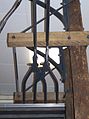
Soft a slotted tube catenary of FOTG in the Transport Museum in Frankfurt - Schwanheim

Pantograph on one of the two poles of the FOTG slotted pipeline

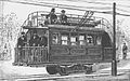
The electric vehicle from 1882, with its two-pole overhead contact line, is considered the ancestor of the overhead line bus


Slotted pipe contact line
After the first electrically powered trains were supplied via the rails or a third conductor rail from 1879, there was a first application of a traction current supply by means of overhead lines on a tram in Paris in 1881. According to the information, it was a slotted pipe contact line.
These first contact lines, which were attached above head height or above vehicle height, consisted of one or two tubes with a slit on the underside, in which longitudinally movable metal boats were located as pantographs for the locomotive below . These grinders were pulled along by the vehicle on ropes or rods.
This system was also used in 1884 by the Mödling – Hinterbrühl local railway and the Frankfurt-Offenbacher Trambahn-Gesellschaft (FOTG) and, from 1888, on the Vevey – Chillon tram in Switzerland.
Lateral position above the track

The first overhead lines were also often hung next to the track at a suitable height. This initially avoided the more complex installation with cantilevers in the middle of the track. Railways on which this was carried out were, for example, the above-mentioned Paris tram, the test route of the study society for electric high-speed trains on the military railway near Berlin, the former Maggia Valley Railway in the Swiss canton of Ticino , the tunnel route of the Baltimore and Ohio Railroad and the flat route of the Oberweißbacher Bergbahn . The lateral arrangement of the Uetlibergbahn in Zurich was chosen so that the same track could be electrified with direct current for the Uetlibergbahn as well as with alternating current for the Sihltalbahn .
They are also used in modern electric mine railways , as the side contact line does not prevent the open trolleys from being filled from above.
Single contact line

A mechanically simple design is used primarily on trams , but occasionally also on mainline railways, which should be electrified at low cost. For example, additional suspension ropes and complex tensioning and damping constructions are dispensed with. The possible spacing between support points is smaller than with more complex contact line systems. Due to the lack of vibration damping, speeds of up to about 100 km / h are possible with the by-wire suspension; on side tracks in some countries such as France and the successor states of Yugoslavia, the single catenary is also used with a voltage of 25 kilovolts and the by-wire suspension is dispensed with.
The single contact line was mainly used for operation with roller pantographs . A sliding of the pantograph is a typical phenomenon that can occasionally be observed. Since the line does not have to be routed in a zigzag, the tendency to oscillate is lower. Today the single overhead contact line is used in some city centers so that the overhead contact line is less of a visual disturbance. A low driving speed is usually required here anyway.
Catenary
Chain catenary (also called catenary) is the standard overhead contact line design in many countries. It consists of the contact wire, the suspension cable, hangers, and in some cases side ropes, as well as power connectors that are movably braced to the track's longitudinal axis. Due to the catenary design, larger field spans between the support points are possible. The sag of the contact wire can thus be regulated. The installation of a side rope (so-called Y-side rope) offers a greater elasticity of the contact line, which enables higher speeds of electric traction vehicles; In many countries, people do not use it. The maximum length of a post-tensioned section in Germany is 750 meters in each direction from the fixed point.
Contact wire and suspension ropes


The grooved contact wire commonly used has a basically circular cross-section from which two V-shaped grooves are cut out in the upper half so that retaining clips can engage there. This design prevents the pantograph from touching the suspension elements. Common cross-sectional areas are 80 or 100 mm² (diameter about 10 to 12 millimeters, about 0.9 kilograms per meter), cross-sections of 120 mm² are used on lines with higher speeds of the DB AG. The geometric dimensions for various cross-sectional shapes and cross-sectional areas from 100 to 150 mm² as well as mechanical and electrical properties of the contact wires are regulated in Germany in DIN EN 50149.
The auxiliary suspension cables are made of bronze. Together, the ropes weigh around 1.4 tons per kilometer .
Suspension and guide


As a rule, spun concrete or steel flat or lattice masts are used, the latter at support points loaded in the longitudinal direction of the track, especially for post-tensioning.
At the support points, the catenary is generally supported by a cantilever structure made of several tubular rods that roughly form the shape of a "Z". The side brackets, which guide the contact wire laterally, are attached directly to the boom in contact line designs for lower speeds and are alternately subjected to tension and pressure so that the contact wire zigzag in the horizontal plane. This prevents the contact wire from grinding grooves in the graphite contact strips of the pantograph . In Germany and Austria the deflection is 400 millimeters on both sides of the center line, in Switzerland only 150 millimeters for R-FL (over 125 km / h) and 200 millimeters for N-FL (up to 125 km / h) due to the smaller clearance profile . Because of this profile, the collector strips in Switzerland are also narrower at 1450 millimeters than in Germany and Austria (1950 millimeters). On high-speed lines of the DB (type Re 250, Re 330 and SICAT H 1.0) the so-called contact wire lateral position over the center of the track is ± 300 millimeters.
An additional support tube is installed at each support point for contact lines for higher speeds. This means that the side brackets are uniformly subjected to tensile loads and can also be smaller and lighter.
A suspension cable carries the actual contact wire and holds it reasonably horizontally above the track. The suspension rope sags in a chain line . The hangers on which the contact wire is suspended on the support cable are of different lengths, so that the contact wire runs almost horizontally (hence the name chain contact line). In order to dampen the overhead wire lift that occurs when pantographs pass quickly, the suspension of the suspension cable for overhead contact line types for higher speeds is also designed to be flexible. For this purpose, a Y-rope is installed at the support points , which in turn carries the contact wire in the support point area via one to four hangers and prevents the accumulation of mass that would otherwise occur at the support points and cause the pallets to jump when passing through.
In France in particular, the increased design effort is also dispensed with on high-speed lines. To compensate for this, the pantograph pallets are again cushioned against the frame. The lower mass of the pallet can therefore better follow changes in the height of the contact wire.

The suspension cable alone is not enough to keep the contact wire in its target position, especially when it comes into contact with the pantograph and when there is thermal expansion. Therefore, the contact wire is also tensioned taut. This is done for the maximum 1.5 km long tensioning sections of the contact wire using tensioning mechanisms on the masts, which tension the support cable and contact wire together (via a double support lever) or separately. In the case of low-speed lines, there are partially semi-retensioned contact lines where only the contact wire is tensioned, but not the support cable. The contact wire is tensioned with tensile weights, which consist of concrete or steel rings ( cookies in railway jargon ) stacked on top of each other on vertical poles . In the case of wheel tensioning systems, a large roller on which the steel cable on which the weight hangs is wound is used to increase the weight; on the same axis there are rollers of smaller diameter on which a rope is wound, which forms the extension of the contact wire. The toothing of the role serves to absorb the weight if the contact wire breaks. In some countries, such as Switzerland, a pulley system serves the same purpose.


The non-continuously connected contact wire sections are led out from or to the fastening points on the mast or the tension weights laterally or into the next section of the route so that at the transition points a longitudinal overlap (so-called section separation or retensioning) with the contact wire of the next or preceding one Section. The contact strips of the current collector each touch at least one of the contact wires that are electrically connected to one another with a short piece of stranded wire. This guarantees an uninterrupted electrical supply along the chain of separate contact wire sections. In the case of a line separation, the distance between the live parts is increased compared to post-tensioning. This reliably prevents flashovers between the two parts even when one is switched off and grounded. Another advantage is that the section concerned can be repaired relatively quickly in the event of overhead line faults. In Austria, simple section insulators are used for cutting.
As a rule, the contact wire runs in an approximately straight line between the brackets, i.e. it forms a polygon in the track curve. To ensure that the permissible lateral deviation is not exceeded, it is necessary in tight bends to reduce the mast spacing or to install a bow deduction in the middle of a contact wire field, in which instead of the boom, two cables pull the support cable and the contact wire to the outside of the curve. In the case of semi-retensioned contact lines on curved lines, crooked contact lines are sometimes used, in which the hangers in the curve are not vertical but inclined, so that the support cable pulls the contact wire a little outwards on each hanger; In this way, even very narrow arches can be spanned without the masts having to be too narrow. The outriggers can then also be made simpler at arch support points, since only the support rope is suspended from the mast.
In some countries, for example in France and Spain, there are still routes with permanently guyed chains. Examples of this are the Bordeaux – Irún line with the arched portal masts of the old Chemins de fer du Midi and Barcelona – Cerbère , the latter in particular between Gerona and Cerbère. The catenary, which sags more at higher temperatures, was the reason for the world record runs of the SNCF on 28/29. March 1955 to be relocated to the usually cool spring, where a more stable contact wire position could be expected.
Multipole contact lines

The overhead line of railways is usually single-pole, the return of the current then takes place via the wheelsets and the rails. In trolleybus networks and comparable facilities, a two-pole contact line must be used due to the lack of a return line through the route. In the beginning, a two-pole overhead contact line was also used for trams, as the return line via the rails was only introduced later. The first tram from Siemens in Berlin , however, used both rails as separate feed lines to the drive motor, with leakage currents through the wooden sleepers and through the ground.
There were also railways with two-pole direct current overhead lines and a neutral center conductor over the rail, such as the Chemin de fer de La Mure .

In a few earlier test drives with three-phase vehicles, three-pole contact lines were arranged one on top of the other next to the track and grinding brackets attached to the side of the traction vehicles in three levels were used. This type of drive with simple three-phase motors - three-phase current has the advantage of creating a so-called rotating field with continuous torque - could not be expanded any further because this arrangement does not allow uninterrupted power supply via switches and crossings . The structure of the ship lift at the Krasnoyarsk Reservoir can be described as an electro-hydraulic rack railway with a turntable. Three upward-pointing pantographs are mounted next to each other on a side-by-side jib protruding from the side.
The Italian state railway Ferrovie dello Stato (FS) had a three-phase contact line network with a voltage of 3.6 kilovolts and a frequency of 16.67 Hertz in northern Italy from 1905 to 1976 . The overhead contact line consisted of two contact wires arranged horizontally next to each other, for each of which two pantograph brackets were available on the locomotives. The rail formed the third electrical pole of the three-phase system. There are still four three-phase cogwheel railways around the world ( Jungfrau Railway and Gornergrat Railway in Switzerland, the Chemin de Fer de la Rhune in the French Pyrenees and the Corcovado mountain railway in Brazil) and still use systems with the same catenary arrangement. In order to ensure an uninterrupted power supply to all phases in the switch area, the traction vehicles run on such routes with raised pantographs at both ends of the vehicle. In the area where the two phases intersect, the pantographs are guided by an electrically neutral contact wire section.
Today's common locomotives generate the multi-phase three-phase current for the three-phase drive motors with on-board frequency converters from the single-pole contact line, which is fed with direct or single-phase alternating current .
Variants and related systems
Busbars have the same purpose as overhead lines, but are usually installed next to the track. They are used on S-Bahn and U-Bahn trains to keep the clearance profile small on routes with many tunnels or many bridges over the route, or on routes on which the erection of catenary masts seems unfavorable due to the risk of avalanches (example: Martigny route (CH ) - St. Gervais (F)). Because of the considerably larger cross-section, they also allow a greater current strength.

For tunnel sections on new lines more and more emerging as an alternative to the contact wire conductor rail from. Fire tests show the much better resistance to fire, which is of particular importance for the evacuation of trains in the event of fire. The overhead conductor rail is used, for example, on a 2.2-kilometer section on the Vienna - Salzburg route , in the Zurich S-Bahn station, in the Leipzig city tunnel or in the Berlin main station and the north-south long-distance railway tunnel . Since May 29, 2007, a 1.6 kilometer long double-track tunnel in Vienna between the Vienna Central Station (formerly Südtiroler Platz) and Vienna Quartier Belvedere (formerly Südbahnhof) has been supplied with an overhead conductor rail. The low overall height and mechanical strength were important here, as the ceiling construction of the Vienna Hauptbahnhof stop (formerly Südtiroler Platz) had to be replaced with the existing overhead contact line.
On the Murg Valley Railway , an overhead conductor rail was used in many tunnels, as the route was only electrified afterwards and the lower overall height meant that there was no need to expand the clearance .
Intersections

Crossings are usually very acute-angled on long-distance railway lines, so that the crossing contact wire approaching from the outside in the course of a passage can be continuously passed under by the contact strip of the pantograph ; the outwardly downwardly curved approach or end horns of the pallets allow safe driving under lower-lying contact wires that approach the main contact wire from the side.
In the case of single and double crossing switches with internal tongues, the usual span of an crossing is usually sufficient. Two contact wires with spacers are laid next to each other for each straight line via cross-points with external tongues.
The right-angled crossings, which are particularly common in trams, must be designed in a special way, since the contact strip can get caught in the traversing contact wire at simple wire crossings. For this purpose, the contact wire level is usually lowered at the crossing point so that the crossing contact wire is set down from the contact strip upwards. For this purpose, downwardly curved crossover plates, crossover discs or wire spacers are used.

Junction (cross plate)

Junction (round sheet)
Crossing of trolleybus and tram contact lines in Geneva

Catenary crossing between tram and trolleybus (Athens)


safety

An installed contact line is usually under full voltage at all times in order to ensure operability and to be able to monitor the insulation. This is also the case if the track in question is rarely used, seems unused or vehicles are parked there.
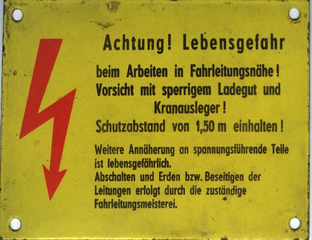
As with all bare, live electrical lines, there is also a risk of electric shock with overhead lines . In the case of railway systems that are operated with high voltage, no direct contact with live parts is required. Even if you approach the overhead line too closely, voltage flashovers can occur through the air and life-threatening arcing faults can occur.
For this reason, contact line systems are designed in such a way that dangerous approaches to live parts are ruled out during normal use of the railway systems by travelers and other people. On the open road, the risk of a dangerous approach is structurally minimized as far as possible, for example by using climbing protection devices on masts and obstacles on bridges under which overhead lines run.
Safety distance
As with all overhead lines up to 30 kV, the specified safety distance for non-electrical work in the vicinity of live parts that are operated with 15 or 25 kilovolts is 3 meters; this may be reduced to 1.5 meters by electrically trained persons .
The minimum distance may only be fallen below when the voltage is switched off and then all of the lines involved (with an earthing rod that was previously connected to the rail with a terminal) are earthed or short-circuited . Proceed in the order of the five safety rules.
Accidents
Despite all protective measures, negligence or willful misconduct leads to life-threatening or fatal accidents - for example when climbing on wagons or overhead line masts or while surfing the S-Bahn . In addition, there were occasional fatal accidents due to overhead cables hanging down after damage from storms or improper vegetation work on the edge of the route.
As part of planned work near overhead lines, there were five dead and eight seriously injured in Germany between 2008 and 2012, including:
- November 3, 2010, Triberg in the Black Forest : A worker came into contact with the overhead line while mowing a steep slope and was seriously injured
- October 10, 2011, Baunatal-Guntershausen train station : One dead person
- November 24, 2011, S-Bahn station Munich-Westkreuz ( Aubing ): One dead
- July 16, 2012, Hanover-Nordstadt train station : Two craftsmen died while cleaning the track after their ladder had been blown into the overhead line. A few days later, a work instruction , which had been completed in April 2012 and entitled Work in the vicinity of electrical systems, was commissioned to external companies at Bahn AG - it had initially been stopped by a senior rail manager - came into effect on August 1, 2012.
- July 31, 2019, Dortmund Hauptbahnhof : A worker with his lifting platform got too close to the overhead line and was killed by a flashover. The overhead line should actually be without power as planned. The work was then suspended for several weeks.
- On June 22, 2020, a train driver from the cantus railway company was seriously injured by a drooping overhead line on the Göttingen – Bebra railway line. The train collided with a drooping section of the overhead contact line after a bird shorted out and damaged a bracket. As a result, a fire broke out in the driver's cab.
Keeping vegetation free
In order to prevent branches of trees or bushes from obstructing the free movement of the pantographs, the overhead lines must also be kept free of vegetation. This is done either by machine as part of the so-called vegetation control or manually by so-called route maintenance .
Overhead line at funiculars
Occasionally, funiculars are also spanned with a simple type of overhead contact line, which, however, only serves to supply the lighting and, if necessary, a heater built into the car.
In addition, with old systems, a wire loop connection can also serve as a transmission for an intercom system. This is possibly only carried out in the vicinity of the stations. For a long time, however, commercial radio has dominated.
Contact line contacts

Especially with trams, but also with mainline railways, contacts can be attached to the overhead line, with which, for example, the track occupancy signal is given. Until the mid-1990s, trams were also frequently used to control the points via these overhead contact line contacts, whereby the position of the points could be influenced via the current consumption of the vehicles. The position of the switch could be changed depending on whether the railcar was consuming power or rolling without power (how exactly, differed between the individual companies). Because the traction vehicles also consume energy for additional and auxiliary equipment in addition to traction current, which can lead to undesired switch changes, this is now prohibited in Germany.
Overhead line on model railways
Overhead lines (usually not to scale) are also available for almost all current electrically operated model railways . The overhead line enables a prototypical power supply for models of electric locomotives and electric multiple units. Electrically conductive model overhead lines enable the operation of another independently controllable vehicle on analogue controlled railways, as an additional separate electrical circuit is available.
However, as the size of the system increases, the wiring effort increases disproportionately, since all power feeds and holding sections also have to be carried out for the overhead line. In times of digital multi-train control , such complex circuits for controlling the locomotives are no longer necessary.
Since the 1980s model railway overhead lines are often called pure mock up (eg rubber thread of. Arnold - Track N -Oberleitung). These have the advantage that the overhead lines can be made thinner and thus more true to scale, especially when the pantographs are fixed just below the contact wire height and do not press against the contact wire. While this means that overhead lines in hidden sections of the route can be dispensed with, the overhead lines can be replaced by cheaper alternatives (e.g. perforated sheet metal strips or simple wire) in the case of a live replica.
Since the contact wires can usually not be reproduced thinly to scale anyway, some model railroaders are now even going over to completely foregoing the reproduction of tensioned wires and only erecting the masts. In special cases, this can create a more realistic overall impression than with taut contact wires.
Various types of single-pole overhead contact lines are offered. Model railways with two or three-pole overhead lines are not produced commercially, as such systems are very rare in the prototype.
See also

literature
- Friedrich Kießling, Rainer Puschmann, Axel Schmieder: Contact Lines for Electrical Railways. Planning, design, implementation. Publicis Corporate Publishing, Munich 2001, ISBN 3-89578-152-5 . (engl.)
- German: Friedrich Kießling, Rainer Puschmann, Axel Schmieder, Peter A. Schmidt: Contact lines for electric railways - planning, calculation, execution. 2nd edition, Teubner, Stuttgart 1998, ISBN 3-519-16177-X .
- Heinz-Herbert Schaefer: Fixed systems for electrical train transport. (Railway teaching library of the Deutsche Bundesbahn, vol. 125). 3rd edition, Josef Keller Verlag, Starnberg 1975, ISBN 3-7808-0105-1 .
- Dieter Schmidt-Manderbach: Development history of the overhead lines for main railways in: 1879 1979. 100 years of electric railways . Josef-Keller-Verlag, Starnberg 1979, ISBN 3-7808-0125-6 ; Pp. 145-159
Web links
Individual evidence
- ^ A b Michael Taplin: The History of Tramways and Evolution of Light Rail. 1998.
- ^ Ordinance of December 5, 1994 on railway electrical systems (VEAB). (PDF; 133 KiB)
- ^ Heinz Delvendahl: The railway systems in the new railway building and operating regulations (EBO) . In: The Federal Railroad . tape 41 , no. 13/14 , 1967, ISSN 0007-5876 , pp. 453-460 .
- ↑ Ril 810.0242 Section 2 Paragraph 1
- ↑ http://homepage.hispeed.ch/wili-the-wire/doc/schwach/Textband/Kapitel_11_11.1_Regelfahrlinien_1950_der_DB.pdf
- ↑ limited preview in the Google book search
- ↑ limited preview in the Google book search
- ↑ TM 08/1999 NEE2
- ↑ Leaning contact line (Furrer & Frey) Example image of a leaning contact line
- ↑ Young woman survives railway accident: 15,000 volts instead of a starry sky. In: Spiegel Online . Retrieved August 28, 2016 .
- ^ Deutsche Bahn AG: Dangers on railway systems. ( Memento of the original from July 1, 2010 in the Internet Archive ) Info: The archive link was inserted automatically and has not yet been checked. Please check the original and archive link according to the instructions and then remove this notice.
- ↑ Assistance in the track area of the DB AG. (PDF) (No longer available online.) DB AG, archived from the original on September 24, 2016 ; accessed on April 21, 2017 . Info: The archive link was inserted automatically and has not yet been checked. Please check the original and archive link according to the instructions and then remove this notice.
- ↑ Danger areas on the tracks. (PDF) (No longer available online.) P. 4 , archived from the original on September 15, 2016 ; accessed on September 8, 2016 . Info: The archive link was inserted automatically and has not yet been checked. Please check the original and archive link according to the instructions and then remove this notice.
- ↑ ÖBB 40 R 8 Written operating instructions for employee protection. P. 24 , accessed October 10, 2016 .
- ↑ Christoph Georg Wölfl, Christoph Wölfl: Accident rescue: tactics, technology and rescue equipment; with 32 tables . Schattauer Verlag, 2010, ISBN 978-3-7945-2684-0 ( limited preview in Google Book Search [accessed October 10, 2016]).
- ↑ GUV-I 769: Safety measures when working on contact line systems. (PDF; 126 KiB) Section 4.4 “Working near live parts”. (No longer available online.) Bundesverband der Unfallkassen, April 2000, p. 21 , archived from the original on November 7, 2016 ; accessed on October 7, 2016 . Info: The archive link was inserted automatically and has not yet been checked. Please check the original and archive link according to the instructions and then remove this notice.
- ↑ Collection of company regulations. (PDF; 1.3 MiB) (No longer available online.) Fels Netz GmbH, December 8, 2007, p. 41 , archived from the original on February 22, 2017 ; accessed on September 29, 2016 . Info: The archive link was inserted automatically and has not yet been checked. Please check the original and archive link according to the instructions and then remove this notice.
- ^ Friedrich Kiessling, Rainer Puschmann, Axel Schmieder: Contact lines for electric railways: planning, calculation, execution, operation . John Wiley & Sons, 2014, ISBN 978-3-89578-916-8 ( limited preview in Google Book Search [accessed August 29, 2016]).
- ↑ Kögler / Cimolino: Standard rules of use: Electric current in use . ecomed-Storck GmbH, 2014, ISBN 978-3-609-69719-2 , p. 877 ( limited preview in Google Book Search [accessed August 6, 2016]).
- ^ Matthias Schleinkofer: Railway grounding - Nittendorf volunteer fire department. In: ff-nittendorf.de. Retrieved August 28, 2016 .
- ↑ Man is caught on fire by electric shock. ( Memento from June 1, 2009 in the Internet Archive ) In: Frankfurter Rundschau. May 29, 2009.
- ^ List of dead and seriously injured from 2000 to mid-2011. In: eisenbahnsicherheit.de
- ↑ Bastian Obermayer: Death comes from above. (Part 1) In: sz-magazine 28/2014
- ↑ a b c d Death comes from above. (Part 2) In: SZ-Magazin 28/2014
- ↑ Death comes from above. (Part 3) In: SZ-Magazin
- ^ Stefan Meinhardt: Electric shock: Worker (28) dies at Dortmund Central Station. August 1, 2019, accessed on September 18, 2019 (German).
- ↑ Oliver Volmerich: RN + tragic accident delays work at the main train station - rail commuters feel the effects. Retrieved September 18, 2019 .
- ↑ Overhead line torn down: train driver seriously injured. In: FFH. June 22, 2020, accessed July 30, 2020 .