
Traction power line


_2011-03-25_15-17-42.JPG)
A traction current line is a high-voltage line for supplying electricity to electrified railways . Railway power lines supply the substations , which in turn feed the locomotives via the contact wire on the railway line (feed line). This system is also known as the central traction power supply - in contrast to the decentralized traction power supply , in which the energy is provided from the public power grid.
From the outside, traction power lines can usually be recognized by the fact that they carry 2 or 4, in rare cases 8 conductors . The traction current network is largely independent of the three-phase network, which is used for the general power supply and whose lines usually consist of 3 or 6 conductor cables.
The traction power grids in Germany, Austria and Switzerland are interconnected, for example via the Muttenz – Haltingen traction power line .
Operating mode
Railway power lines are operated symmetrically to earth. In the case of a 110 kV railway power line, each of the two conductors of a circuit thus has a voltage of 55 kV to earth, the phase positions of these voltages being offset from one another by 180 °. The frequency of the traction current was contractually set for the first time in 1912 at 16 2 ⁄ 3 Hz (≈16.667 Hz), which was exactly one third of the frequency of the three-phase network (50 Hz). However, since this whole-number ratio led to disadvantageous side effects in converter plants that convert three-phase current into traction current, the traction current frequency was increased uniformly by 0.2 percent to exactly 16.7 Hz in 1995.
The traction current network is grounded in larger substations and in railway power stations using Petersen coils to extinguish the earth fault current. As with all symmetrical power lines, traction power lines are twisted .
While in Germany and Austria almost all traction power lines are operated with 110 kV, the same voltage as in the public three-phase network, in Switzerland the voltage levels 66 kV and 132 kV are to be found. To supply the Vienna S-Bahn , some traction power lines in the area of the Austrian capital are operated with 55 kV (line Auhof - Hütteldorf and line ring Hütteldorf - Meidling - Simmering - Floridsdorf - Hütteldorf ).
history
Beginnings of traction power supply
During the first electric railway that by 1879 Siemens & Halske in Berlin was built and presented, nor with a DC - series motor was operated, was already around 1900 large area in the course of attempts to use electric power for railways found that large due to the Distances an economical operation of electric railways can only be possible with alternating current.
The first electrified railway line in Germany was the Ammergaubahn between Murnau and Oberammergau in 1905, which was supplied with single-phase alternating current at a voltage of 5.5 kV and a frequency of 16 Hz from the Kammerl hydropower station . The originally planned operation with three-phase alternating current was not possible due to technical problems that were not yet manageable, which is why the railway went into operation on April 5, 1900 with steam locomotives and was only later converted to the specially developed LAG No. 674 to 677 locomotives .
In 1909, under the leadership of the Royal Railway Directorate Halle , electrical test operations began on the long-distance route between Dessau and Bitterfeld . To provide electrical energy, a power station was built in the nearby Muldenstein , which was fired with lignite from the area ( Central German district ). On January 18, 1911, the 40th anniversary of the founding of the Reich , electrical operation between Dessau and Bitterfeld was started with an initial voltage of 5 kV at a frequency of 15 Hz and locomotives from the Ammergau Railway. It was not until April 1911 that the voltage of 10 kV was used. From June 1911, only electrically powered locomotives were on the road.
The great success of the project prompted the Prussian state parliament to approve further test routes in Anhalt and Silesia . Because the possibility of installing compact rectifiers on the trains did not exist at the time, it was still not possible to transfer the public network frequency from 50 Hz to the traction current. In Prussia, the voltage, corresponding to the Dessau – Bitterfeld route, was initially set at 10 kV for new projects and the frequency at 15 Hz. However, the need quickly arose to operate a uniform system for possible electrification across the empire.
In the agreement on the execution of electrical train transport , the Prussian-Hessian , Baden and Bavarian state railways finally agreed on a voltage of 15 kV with a frequency of 16 2 ⁄ 3 Hz - this corresponded to exactly one third of the frequency in the public network of 50 Hz. Austria , Switzerland , Norway and Sweden later joined the agreement.
In 1913, after three years of construction, the Saalach power plant in Bad Reichenhall went into operation to feed into the nearby Freilassing – Berchtesgaden railway line . In the same year, the Muldenstein power plant was converted to the newly defined operating voltage. This means that the electrical operation of the railway line from Dessau to Magdeburg and from Bitterfeld to Leipzig can be expanded.
Until the temporary cessation of electrical operations due to the First World War in August 1914, a substation was built in Leipzig - Wahren , which was supplied via a 60 kV line from the Muldenstein power plant and fed into the overhead line.
Railway power network in Silesia
With the approval of the Prussian state parliament, electrification of the Lauban - Königszelt railway line and some of the branch lines began in 1912 . A total of 9.9 million marks were made available for this project.
A power plant was built in Mittelsteine from 1912 , which was fired with coal from nearby pits. To feed the electricity generated there into the catenary of the railway line, four tower-shaped substations with enclosed switchgear were built along the line at Nieder Salzbrunn, Ruhbank, Hirschberg and Lauban. Although the construction of the plants began in spring 1913, only the substation in Nieder Salzbrunn could be completed by spring 1914, in addition to the Mittelsteine power plant. Due to the First World War , the completion of all systems stalled, among other things because the contact wire was dismantled for war purposes. It was not until 1922 that the electrification of the railway line was fully completed with the commissioning of all substations. A fifth substation in Wroclaw was planned, but not implemented.
The transmission network for the Silesian railway lines was operated with 80 kV voltage and 16 2 ⁄ 3 Hz frequency - in contrast to today's 110 kV. In the four substations, the voltage was stepped down from 80 kV to 15 kV overhead line voltage. In the last expansion stage at the end of the 1920s, the Mittelsteine power plant generated up to 24 MW of traction current.
The overhead line masts were designed to accommodate two systems of single-phase alternating current, so that two conductor cables (a total of four plus earth cable ) were mounted on the rods per circuit . The masts built first had two cross members, of which the upper one was designed to be narrower than the lower one and was braced diagonally upwards. Since this design proved to be susceptible to failure when ice formed, only masts with a traverse were then built. On January 5, 1929, due to heavy icing near Gaablau and Juliansdorf, masts broke, which led to the cessation of electrical rail operations. It was not until January 7, 1929 that electric rail operations could be fully resumed after temporary wooden masts were erected. Not far from the affected area, after a similar disturbance, new masts were erected as early as 1921, which were designed for eight times the ice load and which survived the 1929 icing without damage. Therefore, until 1934, most of the line sections were designed for ten times the ice load by reducing the distances between the masts and thus the sag and using bronze instead of copper for the conductors. The transformers originally intended for the Breslau substation were used for a heating circuit in the Niedersalzbrunn substation.
The following line sections were built:
- Mittelsteine power plant - Niedersalzbrunn
- Niedersalzbrunn - Ruhbank
- Ruhbank - Hirschberg
- Hirschberg - Lauban
- Niedersalzbrunn - Mettkau (feed line 15 kV)
The line from Niedersalzbrunn to Mettkau was originally intended to continue to the planned Wroclaw substation and operated at 80 kV, for which the parts of the line that had been implemented were already designed.
Since after the end of the Second World War, sections of the lines were converted for operation with three-phase current (see section Separating the existing networks ), numerous original masts from the early 1920s have been preserved and in operation:
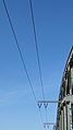
Old traction current overhead line in Silesia, now operated with three-phase current: First used mast type with two ...

... and later used type with a crossbeam

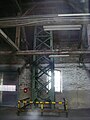
Protection bridge over road

Overview of the mast types used
.jpg)
.jpg)


Expansion in southern Germany

As at first in Silesia, an electrification program of the Deutsche Reichsbahn was carried out in Bavaria . As early as 1897 there were plans to electrify the Bavarian railway lines with energy from the Walchensee power plant planned by Oskar von Miller . After the First World War, however, it was not possible to revisit these plans until the beginning of the 1920s - also because electric rail operations in central Germany and Silesia proved their worth.
In the course of this program, the electrification of initially around 800 km of railway lines in the greater Munich area was planned. The energy for this should come from the Walchensee power plant, which has been under construction since 1918. In addition, several run-of-river power plants were built along the Isar between Munich and Landshut and included in the pipeline network. These were the Aufkirchen , Eitting and Pfrombach power plants . Finally, the Walchensee power plant went into operation in 1924, and the first Bavarian traction power lines were also built from there:
- Walchensee power station - Pasing
- Pasing - Augsburg
- Pasing– Landshut
- Aufkirchen – Eitting – Pfrombach – Landshut
- Walchensee power plant – Holzkirchen – Rosenheim – Traunstein.
In 1927 the Saalach power plant in Bad Reichenhall was connected to the Traunstein – Steindorf line via a single-circuit 110 kV line connection and a line from Landshut to Regensburg - Burgweinting was built.
In the 1930s, the Reichsbahndirektion Stuttgart began electrifying its line from Stuttgart to Ulm ( Württembergische Ostbahn ) including the continuation from Ulm to Augsburg. This project was completed in June 1933. Substations were built in Neu-Ulm and Plochingen to supply the routes, and a turbo set for traction current was installed in the Stuttgart-Münster power plant to provide additional energy as a reserve . A two-circuit traction current line was built from Augsburg via the substations to the Münster power plant and completed in 1933.
After the completion of the electrification between Stuttgart and Augsburg, the state and state governments as well as the Reichsbahn decided to electrify the Nuremberg – Augsburg line, which runs in a north-south direction. In mid-1933, the mostly machine-free work began, which was propagated under the Nazi regime as a job creation measure. Electrical operation began on May 15, 1935 for the first time. A substation was built at Grönhart to supply the catenary, which was connected to the Landshut substation via a two-circuit traction power line.
In 1938, the Grönhart substation was connected to the newly created traction current transformer station in Nuremberg via a two-circuit line. This system was built in the course of the foreseeable electrification of the railway line from Nuremberg to Leipzig and was the first such plant in Germany to convert electricity from the public 50 Hz network into traction current.
While the Bavarian traction power lines were initially laid on masts with two traverses, from the early 1930s only masts with one traverse were built, for example on the Augsburg – Stuttgart, Landshut – Nuremberg, Nuremberg – Leipzig and Landshut – Rosenheim lines.
Traction power network in Central Germany
After electrical operation on the Magdeburg – Leipzig railway was resumed in the spring of 1922, electricity production at the Muldenstein power plant was increased significantly, as further branch lines were electrified. The transmission network operated with 60 kV, which began with the connection from the Muldenstein power plant to the Leipzig-Wahren substation, was expanded to include the Muldenstein – Köthen and Köthen – Marke connections .
Milestones were the electrification of the Halle – Magdeburg line in 1934 and the Nuremberg – Saalfeld line in 1939. Up to 1942, this railway line was continuously electrified as far as Leipzig, which connected the Bavarian and Central German networks of electrically operated railway lines.
For the power supply of the Nuremberg-Leipzig 1939, a double-circuit 110-kV underground power line was built in the traction substation began Nuremberg and substations Zapfendorf , Steinbach am Wald , Rothstein and Großkorbetha for substation Leipzig-Wahren led. This established a connection between the Bavarian traction current network and the central German network around the Muldenstein power station.
Line construction in Austria
The electrification of the routes of the Austrian Federal Railways and the associated construction of traction power lines began in 1937 and was promoted by the electrification department of the Austrian Federal Ministry of Transport in Vienna . The first line, completed in 1938, ran from the Vorderstubach switchboard near St. Johann im Pongau over the Lueg pass, past Elsbethen near Salzburg to Steindorf near Straßwalchen .
After Austria was annexed by the National Socialists in March 1938 , this line, now known as the 110 kV traction power line of the Deutsche Reichsbahn in Ostmark , was extended from Steindorf to Traunstein in order to connect to the German traction power network. This line was completed in 1939.
In contrast to the German traction power lines, the lines on Austrian territory were not constructed with steel truss but with concrete masts by the construction company A. Porr (so-called Porr system ). The lines were installed by Siemens-Schuckertwerke and Brown, Boveri & Cie.
A second line connection to Austria led from the Walchensee power plant to Zirl in order to enable interconnected operation between the networks .
Separation of the existing networks
After the Second World War , the Soviet occupying power ordered the dismantling of numerous railway lines and associated supply systems in their occupation zone as a reparation payment , which concerned the networks in Silesia and Central Germany as well as the connection to the southern German traction current network. Most of the traction power lines in Silesia, which is now under Polish administration, have been dismantled (around 80 km), as has a large part of the electric rail network. The line from the Mittelsteine power station to Niedersalzbrunn, like the power station itself, was largely dismantled, as was the section of line from Niedersalzbrunn to Ruhbank up to Obersalzbrunn . The Hirschberg – Lauban and Niedersalzbrunn – Mettkau sections have been partially dismantled.
The line sections not affected by the dismantling were re-used for operation in the public Polish 50 Hz network. In the process, a conductor was removed so that a three-phase circuit could be routed over the masts. Typically these were 110 and 15 kV connections. To this day, these lines in Poland have been laid on the original masts from the early 1920s. There is also a construction with a protective bridge over a road under the masts that are still in place.
The line connection from Nuremberg to Leipzig was interrupted in 1946 and dismantled in the area of the Soviet occupation zone. As a result, the line coming from Nuremberg, which still served the supply of the Nuremberg – Leipzig railway line in Bavarian territory, was operated as far as the Steinbach am Wald substation and from there a non-functional section continued until shortly before the zone boundary . However, it was left standing for a planned electrification of the transit route. The route south of Steinbach am Wald turned out to be problematic, as this line ran for a few kilometers between Wörlsdorf and Welitsch across the territory of the Soviet occupation zone and later GDR . After the construction of the inner-German border facilities in 1961, the Federal Railroad, which was founded in West Germany in 1949, was no longer able to carry out any measures to maintain the route, which is why the trees growing into the line cause multiple earth faults . In 1967 this section of the line was replaced by a line that only ran on Bavarian (West German) territory. Until the masts were renewed in 2017 and 2018, the change between the old and the new route could be traced back to the different mast construction methods.
Network expansion in the Federal Republic
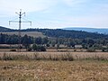
In the 1950s, with the electrification of numerous important railway lines, the network of traction power lines in western Germany grew considerably. Compared to the mast shape with two trusses initially used in Bavaria, the mast type with one truss prevailed. A milestone was the electrification of the Mannheim – Basel railway line in the 1950s. It was supplied with energy from the large Mannheim power station , which has been generating traction current (single-phase alternating current) via a Voith-Marguerre coupling since 1955 . The associated traction current line was moved from Mannheim north via Weiterstadt to Aschaffenburg , where a traction current machine was also installed in the local power plant from 1961 . In a southerly direction, the line then led via Karlsruhe , Offenburg and Freiburg to Haltingen , where from 1957 there was a connection to the 132 kV traction current network of the Swiss Federal Railways .
Many lines in the Rhineland and the Ruhr area were also electrified in the 1950s, for which new lines and converter stations were built. In the 1960s, the traction current network of the Deutsche Bundesbahn ran from Aschaffenburg via Borken and Lehrte to Hamburg and from Borken to the Ruhr area. By the 1970s, the further fundamental expansion between Hamburg, Saarland and Bavaria was largely completed and a continuously meshed network of traction power lines ran through most of the old Federal Republic.
In addition to coal-fired power plants, which also generated traction power, especially in the Ruhr area , the Federal Railroad also increasingly obtained electricity from hydropower plants. Some run-of-river power plants were built on the Danube between Donauwörth and Ingolstadt near Bergheim , Bertoldsheim , Bittenbrunn , Ingolstadt and Vohburg . To connect the grid to the 110 kV level, the original Landshut – Grönhart line was re-routed and connected to the power station switchgear.
Also in the 1970s, two important power plants for traction current were built in southern Germany: on the one hand the Neckarwestheim nuclear power plant and on the other the Langenprozelten pumped storage power plant . Both power plant locations were linked to one another via separate lines. These highly stressed traction power lines were equipped with two or even four bundles. The Flörsheim – Stuttgart traction power line , which was later built as a supplement, and which, in addition to connecting these locations with the large Mannheim power plant , another traction power generator, also serves to supply the Mannheim – Stuttgart high-speed line , was even dimensioned as a continuous four-circuit line with the possibility of expansion to 220 kV. With its traction power supply, the Neckarwestheim nuclear power plant also serves as a replacement for the Stuttgart-Münster power plant, which stopped generating traction power in 1976.
Typical mast of the Deutsche Bundesbahn from the 1950s (line Aschaffenburg – Weiterstadt)

Four-circle route with an introduction to the Eutingen substation

The traction power line from Flörsheim to Stuttgart-Zazenhausen (left) is designed for future operation with 220 kV


Railway power supply in the GDR

Since after the Second World War the Soviet Union was unable to use the electrical railway systems dismantled as part of reparations payments, including the equipment from the Muldenstein power station, they were sold back to the GDR in the 1950s. The traction power generation could thus continue. Since the overhead lines leading away from Muldenstein were also dismantled by the Soviet Union, lines were built on new masts. However, the resulting network only covered the south of the national territory (eastern Thuringia , southern Saxony-Anhalt and Saxony ).
The line masts were similar to the type of mast for three-phase lines in a single-level arrangement , which was widespread in the GDR , but were equipped with either one or two earth cables . Essentially, the pipeline network was a ring starting from Muldenstein, via the Leipzig-Wahren, Großkorbetha , Gößnitz , Karl-Marx-Stadt , Dresden - Stetzsch , Dresden- Niedersedlitz , Böhla , Riesa , Wurzen substations back to Muldenstein. Later pipeline branches were built from Großkorbetha to Weimar and from Gößnitz to Werdau .
In the remaining areas of the GDR, in which there were no traction power lines until reunification, the provision of energy was ensured via decentralized converter stations from the 50 Hz national network. By doing without own traction power lines, the investment costs could be reduced, but more converter sets had to be installed than actually necessary to be able to compensate for the mains supply in the event of a system failure.
Development since 1990
After reunification in 1990, both German networks were reconnected. On March 14, 1995, the Lehrte - Heeren line was put into operation and a connection between the two traction current networks was established again for the first time. In the course of time, the network of new traction power lines expanded to Berlin and from there south to the existing GDR traction power network at the Muldenstein power plant, which was closed in 1994. A second line was on 29 February 1996 between Bebra and Weimar in operation, which largely parallel the A 4 runs. On June 23, 2001, the third connection line between Weimar and Saalfeld was completed. A connection from Steinbach am Wald to Saalfeld was set up as early as 1996, whereby the old masts of the line that had previously ended blindly at the former inner-German border were dismantled and a completely new line to Thuringia followed instead . The lines from Bebra and Saalfeld run from the Weimar substation to Mellingen eastwards on shared masts with two cross members . The upper one goes to Saalfeld, the lower one to Bebra. The lines separate exactly above the Weimar – Gera railway line . The Bebrarer line then goes to the A4 and follows it west.
A fourth newly built pipeline, which crosses the former inner-German border, runs from Lüneburg to Boizenburg in Mecklenburg-Western Pomerania . It is the only traction power line in the state.
It was only when rail lines in Schleswig-Holstein were electrified in the 1990s that the first traction current connection was established in the northernmost German state, which runs from the Nenndorf switchgear south of Hamburg to Jübek near Schleswig . As a special feature, it uses four conductors from the two previously unused circuits at Elbe crossing 2 .
At the beginning of the 2000s, all traction power lines from the 1920s and 1930s in southern Germany were renewed, with the old mast rods being replaced by new constructions on the same route. Since these lines were originally only designed for an operating temperature of +40 ° C and therefore both a minimum distance to the ground, which from today's point of view was considered too low, and an excessively low load limit value , a complete one had to be selected in some places, for example in Germering new route will be built.
The Austrian Porr concrete masts were also replaced by conventional steel framework masts, mostly in the mid / late 1990s, due to their poor condition.
Some of the new traction power lines were built for the numerous new Deutsche Bahn lines that went into operation , for example for the high-speed line Cologne – Rhine / Main or the new Erfurt – Leipzig / Halle line . The Weimar substation was even expanded here.
A single dismantling is currently known: The traction current connection from Holzkirchen to Rosenheim was initially only operated in a single circuit and was completely dismantled in summer 2004.
The German network of traction power lines (as of February 2016) has a total length of 7754 km.
Overhead lines

In order to keep the cable routing short and to avoid unnecessary interference with electrical systems in the area of the route, traction power lines are usually not laid parallel to the railway line, although this is technically possible and is also done in particular along S-Bahn lines.
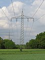
Most traction power lines are designed as overhead lines . Cable routes are only found near some power plants and substations, as well as in some metropolitan areas, such as Basel . Steel truss masts are mostly used as masts in Germany and Austria, while in Switzerland they are laid on concrete masts. A single traction power line has two conductors. A line route usually consists of two lines that can be switched independently of each other, so four conductors are laid (in contrast to three-phase lines, the number of conductors is always an integral multiple of three). Most traction power lines with four conductor cables in Germany are designed in a one- level arrangement , in Austria and Switzerland two-level arrangement is common.
In the case of traction power lines with four systems (eight conductor cables), the two-level arrangement is almost always chosen, with each of the two cross members carrying four conductor cables. The Flörsheim – Stuttgart traction power line , which was built in the 1980s and completed in 1990, uses masts with three levels, with the top two and the bottom traverse each accommodating two systems. It mainly serves to supply the Mannheim – Stuttgart high-speed line . There are also - mostly in the vicinity of substations - traction power lines with six systems (twelve conductor cables), which are almost always designed in a three-level arrangement (four conductor cables per traverse).
Like most overhead lines with operating voltages of 110 kV, traction power lines also rarely use bundled conductors . Only on some heavily used lines, e.g. B. in southern Hesse and Baden-Wuerttemberg, parallel to the high-speed line Hanover-Würzburg and for the direct outlets of numerous railway power stations, bundles of two were installed. The traction current lines from the Neckarwestheim nuclear power plant to the Neckarwestheim traction current switchgear and the Neckarwestheim – Zazenhausen traction current line are designed with four bundles.
Apart from some sections laid on overhead line masts, traction power lines are almost always equipped with an earth wire , only when laying on hybrid masts , for example near Frankfurt-Rödelheim or Neckarwestheim , are two earth wires used occasionally.
Some traction power lines also carry 15 kV feed lines on some short sections near the substations in order to feed railway lines a little further away.
Pipe runs
Laying along the railway line

In urban agglomerations in particular, traction power lines are sometimes also laid along a railway line for reasons of space . Either solid-wall masts with a narrower route profile are built and the overhead line is routed close to the railway line or the traction current line is mounted on the catenary masts above the overhead line .
Since overhead line masts have a smaller cross-section than conventional traction current masts for two systems, the traverses can only have small projections for reasons of strength. Therefore it is usually not possible to run the line with both circuits in a one-level arrangement on the catenary masts. In addition to using the two-level arrangement, on double-track lines, both circuits can therefore be routed separately to the overhead line masts on both sides of the line. Such an arrangement can be found, for example, in the urban area of Böblingen .
The traction current line from Leer to Emden is the only one in Germany that is attached exclusively to overhead line masts and follows the Emsland route . Unlike most traction power lines in Germany, it is single-circuit.
On the Nuremberg – Hartmannshof S-Bahn line (S1), a two-circuit traction current line has been laid continuously on catenary masts until after the Ottensoos stop at km 22.2. It runs from the Nuremberg substation to Neumarkt in der Oberpfalz and was completed in 1987. It is also installed on the catenary masts in Nuremberg Central Station and extends as far as behind Nuremberg Schweinau. The traction current line from the Markt Bibart substation to the Emskirchen substation (Würzburg – Nuremberg line) is also laid continuously on concrete pylons and runs parallel to the line. In contrast to the Emden – Leer line, however, these lines are not installed on catenary masts, but on their own concrete masts.
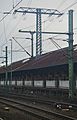
If traction power lines run through stations, they are usually also routed to catenary masts. High tower masts are used, on which also transverse support structures, side arms and feed lines are mounted. Examples are the stations: Station Böblingen , Duisburg main station , Hauptbahnhof Essen , Fulda station , Golm ( Berlin outer ring ), Nuremberg Main , Offenbach (Main) Hauptbahnhof and Bahnhof Singen (Hohentwiel) .
In Austria, the traction current line has been laid on catenary masts along the Drautalbahn from Spittal Millstätter See to shortly before Lienz. The line is single-circuit.
Laying on other routes (hybrid line)
.jpg)
There are also high-voltage pylons that carry circuits for both traction current and three-phase current. Hybrid cables of this type can be found in the vicinity of metropolitan areas, power stations that supply both traction current and electricity for the public network, and around the shared substations of railway companies and power plants for reasons of space . The mast on the right-hand photo carries both a double-circuit 380 kV three-phase current line and a 110 kV traction current line that was built between Flörsheim and Fronhausen near Gießen as part of the establishment of the Rhine-Main S-Bahn . By bundling them on a common route along the BAB 5 , excessive land use in the densely populated west of Frankfurt is avoided.
It is more common, however, to lay them on 110 kV and sometimes also on 220 kV three-phase lines. The common management of three-phase and traction current circuits is mostly limited to short distances due to the capacitive coupling . An unusually long hybrid line (traction current line together with 220 kV three-phase current) runs in the Sauerland between Garenfeld and Elverlingsen.
There are also cables that cross on a mast. The 9127 mast north of Fulda is such a hybrid mast. A 110 kV 50 Hz national line crosses a traverse underneath at a 90-degree angle.
In such lines, the traction current circuits are mostly on one level, at least in the lines implemented in Germany. In Switzerland, even with such lines, it is not uncommon for them to be distributed over several traverses. In Germany, the traction current circuits are also mostly laid on the lowest traverse. An exception is the Flörsheim – Niedernhausen traction power line, where the traction power circuits run along the top traverse of the sections together with a 110 kV three-phase line. At Niederjosbach , masts with five traverses are even used (two-level arrangement of the traction current line and three-level arrangement of the three-phase current line below).
Laying in the route of dismantled three-phase overhead lines
In the course of renovation or new construction of traction power lines, it can happen that these use the space or even the masts of a dismantled three-phase line. The Stuttgart – Plochingen traction power line, which dates back to the 1930s, was renewed in 2008 and partially re-routed: On a section between Neckarrems and Aichschieß , the masts of the Black Forest line (originally 220 kV), which was dismantled at the same time, were rebuilt, with the old traverses removed and new ones Traverses for the accommodation of four conductor cables were installed. The traction power line now follows this route.
The Cologne – Sindorf traction power line, which was completed at the end of 2002, uses the Danube masts of a 110 kV line belonging to RWE that no longer exists on an approximately 4 km long section along the Erft between Kierdorf and Türnich . The two outer conductor ropes on the lowest cross-beam were removed; the remaining four are now used by the traction power line.
Designations
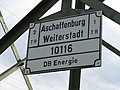
The traction power lines are marked with metal signs that are around 30 × 40 cm in size and have black lettering on a white background. It shows (brackets refer to the example in the picture):
- the arrangement of the ladder (1 TR / 2 TR) in this viewing direction
- the line designations (left Amstetten – Osterburken circuit, right Amstetten – Aalen circuit). The name of the first and last substation connected to this system is given; mere branches that do not interrupt the line are not mentioned. If the designation is the same for both pipe systems, it will only be listed once.
- the mast number (2696). The mast numbers have one to five digits and are only unique per line, not throughout Germany. Leading zeros are possible.
- the operator ( DB Energie GmbH )

Lettering of a high-voltage pylon of DB Energie GmbH
Labeling for two identical circuits

Older lettering from the time before the 1994 rail reform (reference to Deutsche Bundesbahn ). The course of the line with the start and end point and branch as well as the mast location (in front of or behind the branch) is shown here schematically.


Special lines
- The 80 kV line , built in 1921 in what was then Silesia, was the first high-voltage line in the rail network; it was converted to 110 kV three-phase three-phase current after 1945 and is used today for the Polish national network.
- The Flörsheim - Bingen traction power line, built in 1957, was carried on triangular-shaped masts in the Rhineland-Palatinate area. The masts consisted of tubular steel spars that were stiffened by cross-braced steel cables. From 2016 to 2018, almost all of these masts in the section east of Unterwegs Bingen were replaced by standard lattice masts with a square base.
- The Neckarwestheim – Zazenhausen traction power line, completed in 1977, is one of the few traction power lines in Germany with four bundles . Another leads from the Neckarwestheim switchgear station to the Neckarwestheim nuclear power station. The return current line from the ICE line to the Kreiensen substation is also designed as a bundle of four, although it is not part of a traction current line, but an overhead line feed.
- The railway power line of the high-speed line Hanover – Würzburg (Rethen – Gemünden) has 30 successive guy masts in the urban area of Fulda . The northernmost is mast 9124 , the southernmost mast 9095 . One of them, Mast 9108 , stands in a storage shed at the Fulda train station and pierces its roof. Mast number 9127 in the same line is a hybrid mast with a 90 degree crossing 110 kV three-phase line underneath.
- The traction power line Nenndorf - Neumünster - Jübek , which was completed in the 1990s, uses four conductor cables at Elbe crossing 2 , making these crossing masts the highest overhead line masts used by Deutsche Bahn. The highest pure traction power pylons belong to the west of the Weser overhead line crossings Bremen-Industriehafen and serve as a four-circuit traction power line to cross the Weser.
- The Cologne - Sindorf traction power line, completed in 2002, is mounted on cantilevers on both sides of the bridge in the area of the Cologne south bridge.
- The Duisburg - Kirchhellen railway power line runs under a road bridge on the L 155 (Sterkrader Straße) and uses masts with two superimposed half-trusses to keep the line width as small as possible.
- The traction power lines Leer – Emden, Nannhofen – Geltendorf, Markt Schwaben – Grafing, Schönarts – Waigolshausen, Bad Reichenhall junction and, until they were dismantled in 2004, also Holzkirchen – Rosenheim are single-circuit.
- In Hünfeld there is a single-circuit traction power line that originally led to a mobile substation . Since the substation no longer exists, the line ends blindly today. When the insulators on the Flieden – Bebra traction power line were replaced in 2014, it was also disconnected from the traction power network. Nevertheless, the 5 large concrete and one steel mast are still standing. The track for the mobile substation is still there.

Traction power line Flörsheim – Bingen with a triangular mast base. Recording from 2016, until 2018 it was converted to normal lattice masts.

Railway power line Neckarwestheim – Zazenhausen with bundles of four
Mast of the Rethen – Gemünden traction power line in a shed at the Fulda freight station .
The foundation of the mast in the shed.

The Elbe Crossing 2 carries a traction power line (Nenndorf Neumünster)
Railway power line Cologne – Sindorf on the booms of the Cologne south bridge

guyed makeshift masts
Original mast of the former railway line from 1921 in Lower Silesia, the fourth conductor has been removed.


Other lines for traction power supply
The Mariazeller Bahn , operated with single-phase alternating current at a frequency of 25 Hertz, also has its own traction power lines with an operating voltage of 27 kV. These lines are attached to the catenary masts above the catenary.
In the areas around New York there are some railways that also run on single-phase alternating current of 25 Hertz. These railways also have traction power lines, which are mostly attached to the overhead line masts.
In Italy, numerous railways were operated with three-phase current of 16.667 Hertz until 1977. These railways were also fed via their own traction power lines, which were operated at 60 kV. Since these lines were designed like three-phase power lines of the public network, they were far less prominent than the traction power lines of the German-speaking countries.
Some railways for 50 Hertz operation also have traction power lines, for example single-phase high-voltage lines exist for the energy supply of some TGV lines.
Situation with decentralized traction power supply
In Sweden, Norway and Northeast Germany (mainly Brandenburg and Mecklenburg-Western Pomerania), the three-phase current taken from the public network is converted into single-phase alternating current with a frequency of 16.7 Hz in decentralized traction current converter stations. There are no traction power lines in these regions. Also in Wolkramshausen (Thuringia) the Halle – Hann railway line. Münden is a decentralized traction power supply. It is located west of the train station next to a substation and is operated at 220 kV.
Even with railways that run on direct current or single-phase alternating current at the frequency of the public network, the conversion is always carried out in the substations, so that there are usually no overhead traction power lines here. Exceptions can exist in areas where the electric train was the first major consumer, so that the railway company first had to build supply lines for the power supply, or where a re-electrification from a system with central traction power supply to a direct current or alternating current system with mains frequency took place. In all of these cases the traction power lines are three-phase power lines.
Web links
Individual evidence
- ↑ Designation of traction power lines in Austria ( PDF file, 55 kB), accessed on March 6, 2012
- ↑ Agreement on the execution of electrical train conveyance , electrical-bahnen.de
- ↑ The world's first electrified long-distance railway line was opened between Dessau and Bitterfeld in 1911 , WERK-STADT 01 | 2011
- ↑ Drehscheibe-foren.de
- ^ Eberhard Herter: Electrical engineering in Württemberg . BG Teubner Verlag Stuttgart Leipzig 1998, p. 190
- ↑ nordbayern.de: Grönhart substation supplies the railway with electricity. August 27, 2018, accessed January 17, 2019 .
- ^ Archives in Saxony: Deutsche Reichsbahn, Supreme Site Management for Automation and Electrification Leipzig. Retrieved January 17, 2019 .
- ↑ Expropriations for the construction of a 100 kV traction current transmission line from Nuremberg to Muldenstein , German digital library, accessed on June 14, 2016
- ↑ a b F. Rauscher: Renewal of the 110 kV traction power lines Steindorf-Elsbethen / Steindorf-Traunstein, 1999
- ↑ ETR edition 1 + 2 2010, page 14
- ↑ From the history of electricity, year 1946 , Walter Schossig, accessed on June 14, 2016
- ↑ infranken.de: Lines are being upgraded. August 30, 2018, accessed January 18, 2019 .
- ↑ ETR edition 1 + 2 2010, page 15
- ↑ Regenerative traction power - Analysis and concepts for increasing the share of regenerative energy in traction power ( Memento from June 13, 2016 in the Internet Archive ), page 11, accessed on June 14, 2016
- ↑ 20 years of electrical reunification of Germany , Association of Electrical Engineering
- ↑ ETR edition 1 + 2 2010, page 16
- ↑ DB information brochure for traction current, p. 6
- ↑ Summary of the feasibility study linking rail and power line infrastructures, as of July 2, 2012, p. 4
- ↑ Kölner Stadt-Anzeiger from January 24, 2003: Line only disturbs the heart rate monitor. Retrieved June 30, 2016 .
- ↑ OpenStreetMap | Way | Kreiensen - Rethen; Railway return current (28195848)
- ↑ http://www2.pe.tu-clausthal.de/agbalck/vorlesung/energ2001/en-vor09/img_6848.htm (link not available)
- ↑ Archive link ( Memento from May 4, 2009 in the Internet Archive )