
cathode ray tube
The cathode-ray tube (engl. Cathode ray tube , abbreviated as CRT , even Braun tube ) is an electron tube that a focused electron beam generated. This can be deflected or modulated by means of magnetic or electric fields so that a visible image is generated when the electron beam hits a layer of fluorescent substance attached to the inside of the tube . The electron beam generated is not used for direct display for other purposes, for example in an electron microscope , betatron or X-ray tube .
The best-known application is the picture tube in television sets , where it has meanwhile been largely replaced by plasma and liquid crystal (LC) screens.


history
The cathode ray tube with deflection of the beam in horizontal and vertical directions was developed by Ferdinand Braun in 1897 , which is why it is also called the Braun tube. At first it was not known that the radiation emanating from the cathode consists of electrons, which is why the term cathode rays was used for it.
Max Dieckmann suggested the use of cathode ray tubes for television as early as 1906, Braun dismissed this idea as "nonsense like the perpetual motion machine ". This did not prevent Dieckmann from using a Nipkow disk to display mechanically scanned metal templates as shadow images on the picture tube in an experimental setup.
Kenjiro Takayanagi built the first black and white television with a picture tube in 1926. (Before that there were televisions with mechanical image decomposition, see also mechanical television .) He first transmitted a Japanese character with the help of a Braun tube. He later succeeded in the first electronic transmission of a human face. Therefore, he is considered the father of Japanese television.
Manfred von Ardenne has made great contributions to the further development of the Braun tube into a television set, the scanning electron microscope and powerful electron beam sources for industrial applications.
construction

The cathode ray tube consists of a closed, evacuated glass bulb with a hot cathode , the Wehnelt cylinder located in front of the cathode , several focusing electrodes and an anode . The empty glass bulb is under the not inconsiderable air pressure of approx. 1 bar , which clearly corresponds to a load of one kilogram per square centimeter of the bulb. The larger the bulb of the tube, the more stable it has to be, which is achieved by a correspondingly thicker glass bulb wall.
The Wehnelt cylinder is used to control the brightness, but is also intended to prevent the electron beam from diverging (diverging) immediately after its generation. It surrounds the cathode like a pot and has a small hole in its bottom facing the screen through which the beam can exit.
In cathode ray tubes, the anode is often divided. It consists of:
- a pre-acceleration electrode in the form of a cylinder , whose parallel planes lie in the beam path,
for picture and oscilloscope tubes also off
- an electrically conductive coating ( Aquadag ) of the glass bulb in the inner-walled, conical part of the bulb and
- an umbrella at the other end of the bulb. This consists of minerals which, when bombarded by electrons, either emit visible light or, in special cases, absorb light incident from outside to a greater extent.
The luminescent screen with aluminum backing on picture tubes and (on color picture tubes ) the perforated or slotted mask are also at anode potential. On the one hand, the aluminum layer increases the achievable brightness (light falling inwards from the luminous layer is reflected) and, on the other hand, the achievable contrast (dark areas are no longer brightened by scattered light in the bulb). It also prevents the ion spot from forming .
Depending on the type of tube, the outside of the glass bulb is often covered with a thin, grounded graphite layer on the conical part in order to protect the rest of the device from charge equalization processes (see Faraday cage ). This outer layer, together with the inner anode coating, forms a capacitor for smoothing the anode voltage. There are also tube models in which the cone itself is made of metal and in turn is at anode potential. However, this construction could not prevail because of the difficult to control, permanent sealing of the vacuum between the metal cone and the glass screen, as well as for reasons of insulation.
Beam generation

If a high electrical voltage is applied between the heated cathode and the anode , the electrons emerging from the cathode are accelerated by an electrical field and fly through the acceleration field to the screen, on which they generate light through fluorescence.
The speed of the emerging electrons can be calculated to some extent (not relativistically) using the following assumption:
All electrical energy based on the electrical field, generated by a voltage , is converted into kinetic energy when passing through this voltage:


For the electrical energy , the following formula results from the electrical field strength :


By equating with and rearranging according to , the following formula results:


- corresponds to the elementary charge for electrons
- is the amount of electrical voltage that prevails in the electrical field
- corresponds to the mass of the electrons


The image on the right shows the beam system of an outdated television picture tube with an ion trap . The cathode, heated to the point of red heat, cannot be seen. The Wehnelt cylinder and the pre-acceleration electrode can be seen on the far right. This is followed by the anode on the left, in the course of which the jet system bends axially towards the tube neck. The reason for this construction is the separation of the also accelerated residual gas ions from the actual electron beam, which would otherwise cause an ion spot (fluorescent layer destroyed by ion bombardment). Later tubes could do without it because the aluminum-backed screens were less sensitive.
The necessary anode voltage for sufficient excitation of the phosphor is
- for oscilloscope tubes between 500 and 8,000 volts (occasionally up to 24,000 V),
- for black and white TV screens between 14,000 and 18,000 volts,
- for color TV screens 25,000 to 35,000 volts,
- with special tubes for subsequent optical enlargement of the image using optical lenses (projection method) up to 50,000 volts,
- with electron beams for material processing and in x-ray tubes often over 100,000 volts.
Currents in the range below 1 mA per cathode flow , so that the total power consumption of a picture tube can reach a few dozen watts . A simple experiment shows that showing a very bright spot slightly heats the glass (as seen by the viewer) in front of the luminescent layer after a few minutes, while dark areas remain comparatively cool.
To limit the intensity and the quantum energy of the harmful X-ray brake radiation , the acceleration voltage for black and white and color television tubes was limited by technical standards. Devices were advertised for sale with their low acceleration voltage, for example on a sticker, and the acceleration voltage was noted on the rear wall of the housing in accordance with regulations. The tube front screen is made of lead glass in order to absorb the X-rays that are generated when the accelerated electrons hit the screen.
Beam focusing
In order for a sharply delimited spot to appear on the luminous layer, it is necessary to focus the beam along its path.
For this purpose, the anode cylinder is interrupted over a length of a few centimeters in electrostatically focused tubes. At this point, another cylinder with a larger diameter is attached, electrically insulated. The focusing voltage is applied to this cylinder. See also electron optics .
In earlier television picture tubes, traveling wave tubes and electron microscopes, the beam was also focused by magnetic fields that were axial to the beam path.
Beam deflection

By means of deflection fields ( electric fields in oscilloscopes or magnetic fields in television and computer screens) the electron beam can be directed to any point on the fluorescent screen. The deflection fields are generated by electrical voltages on horizontal and vertical deflection plates or by electrical currents in the orthogonally arranged deflection coils.
Magnetic deflection systems are used in picture tubes for televisions and computer screens , since they can be used to achieve a larger deflection angle of the beam and thus a shorter construction of the entire tube is possible.
In contrast, oscilloscope tubes use electrostatic deflection because there is a constant relationship between deflection voltage and deflection angle over wide frequency ranges (up to several GHz bandwidth, typically several hundred MHz bandwidth). The deflection angle and the anode voltage are comparatively small, which is why no excessive deflection voltages are required, but in return the tubes are very long (up to 60 cm) for a rather small diagonal (typically around 13 cm). Due to their long length, these tubes are also more mechanically sensitive than short tubes with magnetic deflection.
A problem with picture tubes are aberrations that have to be corrected. These include u. a .:
- Pillow distortions,
- Fluctuations in image sharpness depending on the position of the light spot.
Both errors have their origin in the fact that, for reasons of better viewing, the luminescent screen is not curved to the extent that would be necessary for a constant distance between the focal point and the cathode.
For the resulting path, which the electrons describe, the assumption that the electrons have a constant speed in their initial direction and that the electrons are deflected (accelerated) in an orthogonal direction via E-fields by combining the formulas (uniform movement ) and , as well as and the following function for the trajectory:


Beam modulation
In addition to deflecting the beam via the luminescent screen, the brightness of the light impression can be changed in that the Wehnelt cylinder receives a more or less large voltage that is negative compared to the cathode. If this voltage changes at a sufficient speed while the beam is continuously deflected, a light track is obtained that is light-modulated according to the applied voltage. This function is therefore one of the most important for the usual display of television images using a grid .
During the line and image return (the jump to the starting positions) the electron beam must be controlled "dark".
The modulation requires a very high bandwidth of the control voltage from zero to several megahertz for image display . It is provided by the video output stages. The amplitude of picture tubes is up to 300 volts.
Color picture tubes

There are three electron beam systems in color picture tubes, the beams of which cross each other in each position in the area of a hole , slit or stripe mask arranged near the luminous layer . Due to their shadowing, they can only hit one of the fluorescent colors of the luminous layer. These are stripes or dots of the primary colors red, green and blue that are arranged to match the mask. The structural dimensions of the mask and the phosphors are smaller than the diameter of the electron beams, so that an almost equal proportion of this always passes through the mask.
The Wehnelt cylinders of all three beam systems of a color picture tube are connected to one another - the three beam currents (and thus the brightness of the light spots) are controlled via the voltage of the cathodes, whose connections are brought out separately.
The following technical requirements and corrective measures are necessary for color picture tubes:
- All three electron beams must always hit one point on the screen together ( convergence is achieved by correction coils in the deflection unit).
- The rays must fall through the shadow mask at the correct angle in order to only stimulate the assigned color points (color purity is ensured by precise production and clean overall alignment of the deflection unit).
The convergence is achieved by using specially calculated and controlled additional deflection coils. To compensate for image distortion, more complex shapes are used instead of straight sawtooth-shaped currents . Often, remaining display errors are corrected by sticking small permanent magnets of various geometries on the tube piston or on the neck during the production of picture tubes.
Magnetic constant fields such as B. the earth's magnetic field can magnetize the shadow mask. To remedy this, there are demagnetizing coils around the piston, which demagnetize the shadow mask when the device is switched on using an alternating current of slowly decreasing strength . Particularly strong magnetizations such as B. by deliberately running a strong magnet along the screen surface cannot be completely eliminated by this integrated demagnetization.
Delta shadow mask color picture tube


In the first color picture tubes and in many computer monitors , the beam generation systems, the shadow mask holes and the fluorescent dots on the fluorescent screen were arranged in the form of equilateral triangles. To achieve sufficient convergence, more extensive correction circuits are necessary than with inline tubes. The image quality is usually better than that of the inline tube types, however
- the otherwise disruptive influences of vertical lines, especially in CAD workstations, are avoided by the also vertical mask structures,
- Color fringing on vertical lines cannot occur due to the principle,
- the arrangement of the light points allows a higher resolution, the structures are finer.
However, the use of electron beams is less effective - a larger part of the electrons ends up unused on the mask, since a shadow mask has a smaller open area than slit and stripe masks.
Delta tubes, however, continued to be used in the professional environment and in high-resolution monitors, for example in the medical field. They were found in high quality computer monitors because the display quality justifies the increased effort. The technical difficulties of convergence with delta tubes that still existed in the early days resulted in increasingly sophisticated deflection coil systems, so that monitors only require a fraction of the correction settings at that time.
Inline color picture tube
The miniaturization of the beam generation systems in the mid-1970s made it possible to arrange them next to one another ("in-line") in the neck of the picture tube, together with a simultaneous reduction in the neck diameter. The fluorescent pigments on the picture tube screen were accordingly also arranged side by side in strips. The number of corrective measures required to achieve beam convergence was thereby reduced considerably. Stripe and slit masks are used, in which, due to the larger relative open area, more electrons reach the luminous layer instead of landing unused on the mask. With a given beam current, these tubes therefore provide a brighter picture than the Delta tubes that have been used up to now.
In the course of time, the inline tube was further developed into the Black Matrix tube. This has an opaque strip of light-absorbing material between the individual light strips. It increases the contrast (the screen surface appears darker in external lighting) and the color purity (the beam limited by the mask can now hit a little more next to it before light strips that do not belong to the corresponding cathode are excited).
At the same time, Sony developed the Trinitron tube, the most obvious difference between it and the inline tube being the use of vertically tensioned wires instead of the slit mask. This in turn reduces the area on which electrons are discharged unused.
The resolution of the inline tubes is poorer due to the coarser slit pattern in the vertical direction, and color fringes are more easily perceptible at hard contrast transitions in the image, although the convergence setting is correct. Aliasing and staircase effects occur on vertical lines, making these tubes unsuitable for CAD workstations.
Inline picture tubes make it possible to almost completely dispense with the previously required complex convergence unit, which made it possible for the first time to construct inexpensive, compact and easy-to-maintain color TV sets. The inline picture tube therefore enabled color television to make its decisive breakthrough in the mass market at the end of the 1970s.

Section of a color picture tube with a slit mask
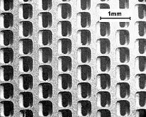
Detail from a slit mask, view from the front

Representation of a white "12" on a black background on a television. The close-up shows the individual colors that make up the characters.


Historical color picture tubes
Chromoscope
The chromoscope developed by DuMont in the USA in the late 1940s (from ancient Greek κρῶμα chroma “color” and σκοπεῖν skopein “look”) consists of a beam generation system known from black and white technology. However, the luminescent layers are not applied to the front glass surface, instead three fine-meshed wire nets coated with the respective colored fluorescent luminescent material are arranged one behind the other at a distance of approx. 1-3 mm, the electrical connections of which are led to the outside. From the cathode point of view, in front of these three networks, there is another comparatively wide-meshed network at the same distance, which, at anode potential, ensures a constant acceleration of the electrons even with alternating potentials of the luminous networks.
By switching the networks between cathode and anode potential, the electrons that have already been accelerated are slowed down by networks that are at cathode potential so that they cannot reach them. Only networks that are at anode potential are hit.
use
The classic cathode ray tube with a fluorescent screen shows different types of electron beam guidance in practice:
- Oscillogram: Here an electron beam travels in the picture tube, usually at constant speed, from left to right across the screen and is deflected vertically depending on the signal curve to be displayed. The electron beam excites the comparatively long fluorescent coating of the screen to glow, so that the impression of a still picture is created.
- Vector deflection: The electron beam writes an image directly onto the fluorescent coating of the screen via two modulated control signals (horizontal) X-axis (abscissa), (vertical) Y-axis (ordinate). Using the beam brightness modulation, this pen can be removed and placed again at another point. Used in early computer games (vector game asteroids , radar).
- Line deflection (raster deflection): The electron beam repeatedly writes the image line by line in the raster process (see following section), very similar to e.g. B. a person reads a book.
Raster images
→ Main article: Cathode ray tube screen

A grid is created on the screen surface for image generation . The electron beam travels at high speed from left to right and at a slower speed from top to bottom, sweeping over the image points line by line. At the end of a line it jumps back to the beginning of the following line. When the lower end of the screen is reached, the beam jumps back to the upper end and the process begins again. This is how a grid is created. The faster these processes take place, the better the impression of a stationary, flicker-free image created by the inertia of the human eye.
The electron beams can be influenced in their intensity at high speed. The current intensity determines the brightness of the individual pixels . In this way, the overall brightness of a pixel can be controlled, as can almost any color mixture. The image content is generated sequentially via the brightness of the beam spots.
Cathode ray tubes have been used in televisions and computer monitors. Here, however, they have been almost completely replaced by plasma and liquid crystal screens, which, due to their principle, have a much flatter structure. Raster graphics are also displayed in some digital storage oscilloscopes, but here with electrostatic deflection as with their predecessors with vector graphics.
TV camera tubes, such as B. the vidicon , also use a cathode ray tube similar principle with raster scanning to scan the charge image.
In older radar devices , cathode ray tubes are used to display images in polar coordinates, in that the angular deflection is carried out by a rotating magnetic deflection system and the range deflection is carried out electrostatically.
Scanning and transmission electron microscopes contain cathode ray tubes to "illuminate" the samples with electrons.
Vector graphics
Cathode ray tubes are used in analog oscilloscopes and various laboratory devices (measuring receivers, wobble transmitters ) to display the measurement results as vector graphics in a right-angled coordinate system. The ordinate is either the time, the frequency or a second measured value.
For early graphics applications in the field of information processing, memory picture tubes were used in which an image, once written, remains until the entire image is reset by a delete command. The image is saved in the luminescent layer; this means that no frame buffer is required. Analog storage oscilloscopes work in a similar way .
Electron beam applications
Scanning electron microscopes contain cathode ray tubes to "illuminate" the samples with electrons. They can often also be equipped for material surface analysis; corresponding methods are, for example, energy dispersive X-ray spectroscopy (EDX), electron beam microanalysis (ESMA) or Auger electron spectroscopy (AES).
So-called electron guns with an output of hundreds of kilowatts for electron beam welding are also basically cathode ray tubes.
Electron radiation is used to crosslink polymers (electron beam crosslinking).
The betatron contains a cathode ray system for injecting the electrons to be accelerated into the accelerator system.
Cathode ray tubes are used in electron beam lithography processes for direct writing or exposure in semiconductor production and for microstructuring / aligning thin-film structures .
In traveling wave tubes , klystrons , carcinotrons and gyrotrons, the electron beam interacts with a high-frequency field and is used to generate or amplify microwaves .
In X-ray tubes , the electron beam hits a metal surface and generates braking X-ray radiation there .
Indirect image generation or projection
The non-self-luminous blue writing tube or Skiatron requires an external light source. Instead of a luminous layer, the electron beam hits an externally visible layer of vapor-deposited alkali halides, usually potassium chloride . The negative charge of the beam causes a discoloration of the affected areas, which appears blue to blue-violet depending on the type. This trace is very permanent (minutes to days) and can be erased by warming up.
The eidophor is an image projection method based on a grid-like irradiated layer of oil.
Manufacturing
The beam generation system is assembled true to size from punched individual parts using gauges using spot welding and welded to the lead-through wires of the tubular base produced in a separate operation. Guides and embeddings made of glass ceramic along the system increase the freedom from vibrations of the structure in the event of shocks. Leaf springs at the end of the structure ensure, on the one hand, the electrical contact to the anode coating on the inside of the cone of the tube and, on the other hand, a more stable hold of the system on the otherwise freely swinging side.
With picture tubes, neck, cone and screen are created in separate operations and fused together. They consist of different types of glass. In the case of oscilloscope tubes, the entire piston including the neck is blown out of one piece by machine - there are fewer requirements for X-ray shielding and the smaller size allows for a lower strength.
Picture tubes have an implosion protection , which consists of a bandage around the screen and there absorbs tensile stresses otherwise occurring in the glass. The metal bands (rim band) also carry the mounting brackets of the picture tube.
Screen pins (steel pins) are melted into the corners of the screen of color picture tubes , to which the Invar steel mask is attached before assembly. The positioning of the mask relative to the screen must be very precise and mechanically stable.
High demands are placed on the glass :
- Optical quality (free of bubbles, stones, streaks)
- Mechanic solidity
- Shielding of the resulting X-rays
- In the case of color picture tubes, coefficient of thermal expansion adapted to the mask
- Good, vacuum-tight connection between the glass and the electrical feed-throughs.
These requirements can often only be met with different types of glass.
The phosphor is applied to the inside of the screen . In order to achieve a coating that is as uniform as possible, the phosphors are mixed with a liquid that is chemically neutral to the phosphor ( suspension ) and slowly deposited on the inside of the screen ( sedimentation ) in a complex, fully automated process . The carrier liquid is then carefully poured off and the phosphor is fixed by firing after it has dried through .
In the case of color television tubes, the luminous layer does not consist of a homogeneous layer, but of many tiny, appropriately arranged points or strips of three different luminous substances in the primary colors red, green and blue. In the case of black matrix tubes, the strips are again separated from one another by a black graphite strip. The stripes or points are structured by photolithography using precisely the mask that will be installed later.
In a further work step, a thin, smooth separating layer is applied to the relatively granular phosphor on picture tubes, on which an aluminum layer is applied by vapor deposition. This intermediate layer is then again removed by firing.
After the glass parts have melted together, the picture tube, like electron tubes, is evacuated , degassed, gettered and artificially aged. The picture tube manufacturer also attaches the magnetic deflection system and correction magnets.
hazards
X-rays
From an anode voltage of approx. 20 kV, X-rays in the form of bremsstrahlung are also generated in the screen of tube televisions, as they were common before flat screen televisions. After the dangers associated with the increased anode voltages, especially after the introduction of color television, had been recognized, international radiation protection regulations and limit values were introduced, which are regulated in Germany with the ordinance on protection against damage caused by X-rays , or X-ray ordinance for short , in Germany from 1987 . In the case of a television set, the local dose rate 10 cm away from the screen surface must therefore not be more than 1 µSv / h in accordance with Section 5 (4) RöV.
The glass of the picture tube cone will lead oxide added. Since this glass turns brown after prolonged exposure to X-rays, strontium and barium-containing glasses are used in the glass for the front, visible screen glass, and for reasons of stability it has a very large wall thickness anyway. Both measures reduce the X-ray radiation emitted.
The acceleration voltage used, which determines the lower limit wavelength of the braking X-ray radiation and thus its "hardness" or penetration capacity, is limited to around 27 kV.
In early television picture tubes, a so-called ion trap with an electron gun installed at an angle and a permanent magnet was used to deflect the beam towards the screen (see picture above).
Implosion protection
The implosion of a cathode ray tube, like that of other evacuated tubes, is very dangerous due to broken glass. It must therefore be avoided and requires special protective equipment (protective goggles, protective clothing) when handling. Today picture tubes have implosion protection in the form of a pre-tensioned metal hoop (rim tape) around the screen. It absorbs the tensile stresses that otherwise occur in the glass and also carries the bracket of the picture tube. However, the implosion protection does not include the neck of the picture tube. If this breaks, it can escape through the screen to the front - unless the screen has sufficient strength (intrinsically safe picture tubes). Picture tubes must therefore not be handled by the neck.
If the electron beam lands on the inside of the tube neck due to incorrect deflection, the picture tube can implode due to thermal stresses. Before that, it releases more X-rays due to the thin glass there. Devices in which the anode voltage is not obtained as usual from the return pulses of the line deflection, therefore often have a device that switches off the anode voltage in the event of a faulty deflection.
The vertical deflection circuit, which operates independently of this, is also often designed so that the beam current is switched off if it fails. This measure also prevents burn-in of a thin and very bright, horizontal line that occurs in the event of a fault.
espionage
The electromagnetic waves emitted by the deflection and brightness modulation of the electron beams ( compromising radiation ) can be captured for espionage purposes and displayed on a second screen with the help of Van Eck phreaking technology.
See also
- Image generation in a color picture tube
- Image intensifier
- Field emission screen
- Surface-Conduction-Electron-Emitter-Display (SED)
Individual evidence
- ↑ Renate Wahrig-Burfeind (Ed.): True. Illustrated dictionary of the German language . ADAC-Verlag, Munich 2004, ISBN 3-577-10051-6 , pp. 158 .
- ^ Arthur C. Brownell: The Chromoscope, A new color television viewing tube. Electronic Engineering, Volume 20, June 1948, p. 190
- ↑ Vector game Asteroids. heise.de, c't No. 17 of July 21, 2008, page 187
- ↑ Blue-writing tube.pdf Blue-writing tube (PDF; 789 kB)
Web links
- Picture tube adapter database
- The Cathode Ray Tube site (English).
- The Braunsche Tube (animated) (State Education Server Baden-Württemberg)
- Distraction in the Braun tube (animated) (State Education Server Baden-Württemberg)
- Meyer's Large Conversation Lexicon . 6th edition. Bibliographisches Institut, Leipzig / Vienna 1909 ( zeno.org [accessed on April 3, 2019] Lexicon entry “Cathode rays”).
- Otto Lueger : Lexicon of the entire technology and its auxiliary sciences . 2nd Edition. Deutsche Verlagsanstalt, Stuttgart and Leipzig 1920 ( zeno.org [accessed on April 3, 2019] Lexicon entry "Braunsche Röhre").