
Stirling engine


The Stirling engine is a heat engine developed by Robert Stirling in 1816 .
In the Stirling engine, a gas is heated and expanded by externally supplied energy in one closed space (cylinder), and cooled and compressed in another closed space (cylinder). The gas oscillates between these two rooms, changing temperature and pressure in the process. The Stirling engine works with a circular process ( Stirling process ). Because the heat is supplied from the outside, it can be operated with any external heat source. Because the gas is not exchanged, a particularly suitable gas can be used, such as helium or hydrogen.
Common Stirling engines ("standard machine") store the heat contained in the working gas on the way from the hot to the cold room in a storage tank ( regenerator ) in order to improve efficiency. The regenerator gives off the heat again when the gas flows from the cold to the hot room. Stirling engines are mostly designed as piston engines, but there are other designs.
For some designs, even small temperature differences are sufficient, for example between the human body and the environment.
history
The Stirling engine was invented in 1816 by the then 26-year-old Scottish clergyman Robert Stirling . It is the second oldest heat engine after the steam engine . With its engine, Stirling wanted to offer an alternative to the high-pressure steam engines that were emerging at the time , which claimed numerous victims through boiler explosions .
The engine experienced its first heyday at the end of the 19th century as a single source of energy in the private households of the emerging bourgeoisie . In small versions it was a mass product of the manufacturer Louis Heinrici and was roughly the equivalent of our modern electric motors . It was used, for example, to drive fans .


In the 1930s, the Dutch company Philips developed Stirling engines to drive small generators. During this period, the company built large quantities of radios for export and was looking for an easy-to-use, transportable prime mover to power the electron tubes in areas with no electrical power supply. In this context, the Philips Stirling engine was developed , an engine with one cylinder and two pistons . While the connecting rod of the working piston acts directly on the crankshaft, the displacement piston is driven by a connecting rod offset by 90 °, an angle lever and an elastic “knife” connecting rod that is guided through a slot in the working piston. Later, Philips used a diamond gear, in which both pistons acted on piston rods that were connected to two opposing crankshafts via yokes and 4 double connecting rods; the piston rod of the displacement piston worked through the hollow bored piston rod of the working piston.
This type
- runs completely without imbalance , is therefore free from first and second order inertial forces and moments,
- can be reduced in size almost at will and
- eliminates the radial loads from the crank mechanism on the piston, which minimizes friction and wear;
however, the fatigue strength of the seal between the two piston rods was initially low, but this was manageable with modern materials and manufacturing processes.
From the middle of the last century, various industrial companies continued to research the Stirling engine as a ship and automobile drive as well as, because of its multi-fuel suitability, in the military sector, without achieving competitive series production in these areas .
In the 1970s and 1980s, Stirling engines were researched as an automobile drive, especially because the continuous combustion of the exhaust gases brought advantages and no sophisticated exhaust gas aftertreatment systems were available for other engine types. Philips had collaborations with GM, Ford and NASA. However, numerous problems of the Stirling engine in the automobile could not be solved satisfactorily, in particular the controllability (slow response behavior), the heating-up time from cold start to driving off and the low power density. In addition, there were efficiencies that reached 38% at the best point and up to 28% under test conditions. In 1969 GM had developed a study of a serial hybrid with a Stirling engine under the name Stir-Lec 1 .
From around 1975 the Stirling engine gained in importance in connection with wood -fired combined heat and power units (CHP) and combined heat and power . There are Stirling free-piston motors with linear generators for small CHP units .
In connection with the Combined Heat and Power Act , projects have become known to return the Stirling engine to a wider range of applications. A free-piston heat engine in which the working machine (e.g. generator ) is driven by a Stirling engine (i.e. it consists of two parts, the generator and the Stirling engine), has the great advantage that there are only two axially loaded parts Operation no radial forces occur.
Like the gas turbine (one moving part), the free-piston Stirling engine generator (two moving parts) is a heat engine that does not require any other friction-prone parts such as connecting rods , crankshafts or even valve controls.
Special features and differentiation from other types of engines
A Stirling engine simulates the Stirling cycle in a machine. The ideal Stirling process has isothermal expansion, in practice only adiabatic expansion is realized due to the high speeds .
A Stirling engine can be driven externally and then works as a heat pump , which - depending on whether the hot or cold area is used - can serve as a cooling machine or heat pump heating .
One advantage of the Stirling engine is its continuous and quiet supply of heat. The combustion can be designed to be low in pollutants or replaced by an emission-free radiation source, such as
- the sun,
- radioactive decay heat or
- hot water or steam from geothermal energy.
While a gasoline or diesel engine requires a lot of effort to operate the internal discontinuous combustion both efficiently and with low emissions, the external combustion can be implemented more easily with the Stirling engine. Because of the continuous external heat supply, the Stirling engine does not need high-quality fuel, it is basically a multi-fuel engine .
Another advantage is the free choice of the working gas (usually helium) in a closed system without external contamination. The working gas is only loaded by abrasion from the sliding parts and possibly by lubricant. Suitable modern lubricants can be designed to minimize gumming so that a Stirling engine has a long service life.
In the Stirling engine , unlike in combustion engines , for example, the working gas remains inside the engine and is not exchanged (so-called hot gas engine). If the external heat source does not produce any exhaust gases , there are no material emissions - but waste heat .
With the Stirling engine, the heat and cooling energy must be supplied and removed by conduction . This creates considerable problems because the heat transfer coefficients of all metals are very unfavorable, at least in relation to the direct heat supply in internal combustion such as in a gasoline or diesel engine. At high temperatures at the focal point of a concave mirror directed at the sun, there is a risk of exceeding the softening point of the alloy of the heat exchanger, as a result of which the gas, helium or hydrogen used as the circulating medium, can escape. With a higher output, this problem can be avoided by the displacement piston pushing the working gas through thin, heated tubes. This has the disadvantage that the " dead volume " V UT is quite large and the achievable power density in W / kg is reduced. Stirling engines with high power therefore have a very high mean operating pressure.
The problematic heat exchange is simplified if a regenerator is used as an intermediate store for thermal energy. The temporarily stored heat remains in the engine compartment, which allows smaller cooling and heating surfaces. The position of the regenerator depends on the type of construction; the amount of heat stored in it can be up to four times the heat supplied.
Designs
.jpg)
A distinction is made between three main types: the alpha, beta and gamma type.
- With the Alpha type, two pistons (with the reciprocating piston design) are housed in separate cylinders and act on a common crankshaft offset by approx. 90 ° to 170 ° (for recommended phase angles see box below). The crankshaft drive with two pistons and connecting rods on a crankshaft journal and the offset of the cooled cylinder ensure that the gas from one piston can be expanded or compressed, while the other piston moves little near top or bottom dead center. Since both cylinders are connected to one another by a pipe and a regenerator, the work cycle (expanding and also compressing) continues in the following cycle on the other top of the piston. A widespread design is the double-acting four-cylinder V-engine, in which the crank drive is relieved of the high pressure of the working gas and the “hot” piston tops interact with the neighboring “cold” piston bottoms. The invention of the Alpha type does not actually go back to Robert Stirling, but to a group of people around Charles Louis Felix Franchot in Paris from 1840 to 1853. Apart from its patents, it is not known that such engines were also built in Paris at that time. It was not until 1870 that 80,000 engines of this type were manufactured by Alexander Kirk Rider in New York, which is why the Alpha type is also called Rider engine.
- Beta type: Both pistons run in a cylinder, whereby the displacer can act as a regenerator at low power. The other piston is the working piston; it converts the pressure amplitudes into kinetic energy and closes the work area. The working piston moves in the continuously cooled cold zone, while the displacement piston is located between the hot zone and the cold zone.
- In the Gamma type, which was the first to be realized by Stirling, the working and displacement pistons are housed in different cylinders connected to one another.
General
All designs are based on the same four steps that allow the Stirling engine to work either as a heat engine or a heat pump. In general, the respective sequence of steps and the associated volumes can be described as follows:
| Heat engine | Heat pump |
|---|---|
|
1 → 2 Expansion of the gas in the hot room when heat is supplied from the hot reservoir |
1 → 2 Expansion of the gas in the cold room when heat is supplied from the cold reservoir |


In the following, the Stirling engine will only be described as a heat engine for the sake of simplicity. For the sake of simplicity, most of the graphics depicting the Stirling engine show two pistons offset by 90 °. However, this does not always have to be the case, depending on the displacement of the two pistons and the existing temperature gradient.
Alpha configuration
The alpha configuration consists of two pistons in separate cylinders. One cylinder is continuously heated, the other continuously cooled. The overtravel of the cold piston is theoretically 90 °, but is usually increased in order to be able to reduce the required temperatures on the hot cylinder and to minimize the forces on the crankshaft bearings (see box "Recommended phase angle").

Most of the gas is in the hot cylinder and expanding

Most of the gas is heated in the hot cylinder and then the pistons push most of the gas into the cold cylinder

Most of the gas is in the cold cylinder, contracting and at the same time being compressed by the pistons

The gas has now cooled down in the cold cylinder and is then pushed into the hot cylinder


The Alpha Stirling configuration is also known as the Rider engine.
Beta configuration

In the beta configuration, two pistons usually run in a common cylinder. The displacement piston can be designed here as a regenerator , it is then axially traversed by many thin channels. The working piston runs as with other configurations on a offset by 90 degrees of the crank of the common crankshaft . The working piston alone does the work, the displacement piston is only moved in order to move the gas between the hot and cold room and to temporarily store its thermal energy. The workflow can be broken down into the following four steps:
Fig. 1 → Fig. 2: The regenerator is at top dead center, the gas at the bottom in the hot area. It is heated by the supply of heat, expands and pushes the working piston upwards. The displacement piston is also moved by the movement of the working piston, but the hot volume always predominates. In this cycle the flywheel is driven because the pressure p of the gas exerts a force F on surface A of the working piston .
Fig. 2 → Fig. 3: The flywheel continues to rotate due to its inertia , the total volume remains almost unchanged at the upper point in this step. The displacement piston now pushes the gas from the hot into the cold area, which heats the regenerator and cools it down itself. The displacement piston takes on the important task of heat storage and must therefore have sufficient mass. In the cold area, the gas is further cooled by cooling fins or a water-cooled jacket, which reduces the pressure.
Fig. 3 → Fig. 4: Now a distinction must be made: At high internal pressure, work has to be added in order to push the working piston back because the high pressure but cold gas has to be compressed. The work to be added is significantly less than the work removed in the case of hot expansion and is performed by the flywheel. If the internal pressure is low, however, work can also be carried out at this cycle, in that the outside air presses the piston of the Stirling engine.
Fig. 4 → Fig. 1: The flywheel continues to turn, the regenerator is moved upwards and shifts the gas from the upper cool area to the hot area, heating it with the heat that was stored in the second cycle. The cycle starts all over again.

A fundamental disadvantage of the "gentle" movement of the regenerator can be seen in the step from Fig. 1 → Fig. 2. Although this has passed its top dead center, the piston continues to move upwards. This allows gas to escape upwards and is cooled there instead of being heated below the regenerator. This systematic error could be avoided if the regenerator was in close contact with the piston in this step. The flat plate Stirling engine is better designed here.
Specializations and variants
- Gamma configuration
- Flat plate stirling engine
- Diamond gear
- Philips Stirling engine
- Ringbom Stirling with a displacer driven by the fluctuating pressure in the work area
thermodynamics
Changes of state


The Stirling cycle consists of two isothermal changes of state and two isochoric changes of state that repeat themselves periodically. It serves as a template for understanding the Stirling engine, but is only achieved with idealized considerations, which is illustrated in the lower pV diagram with the yellow area.
Cycle 1 → 2 is an isothermal expansion starting from volume V 1 to volume V 2 , in which work is performed by the gas and the temperature is kept at T o . The heat Q supplied to maintain the temperature corresponds to the work W ab according to the formula:

The isothermal expansion and thus the working capacity of the Stirling engine is maximized with a working gas that has a high isentropic exponent and a low molar mass . This is why hydrogen and helium are the preferred working gases for Stirling engines. However, the disadvantages of hydrogen are the required explosion protection and sealing against leakage.
Cycle 2 → 3 is an isochoric cooling in which the gas changes its temperature from T o to T u by releasing heat to the regenerator . The amount of heat is:

Cycle 3 → 4 is an isothermal compression at the temperature T u , the volume change work W of which is equal to the amount of heat to be dissipated Q ab :

Cycle 4 → 1 is an isochoric heating from the temperature T u to T o , the heat of which comes from the regenerator and is transferred to the gas. The amount of heat is Q 2.3 and is calculated as follows:

A low molar mass of the working gas increases the efficiency and performance of the engine. The greater the working pressure, the more compact the engine can be. Hydrogen and helium have the highest thermal conductivity , which means that the heat exchangers can be made compact. Hydrogen also has the advantage of the lowest viscosity of all gases, which results in the lowest gas friction losses. Hydrogen has about 2.7 times the heat capacity of helium, which itself has 4.7 times the heat capacity of air.
The following abbreviations apply to the status changes:
- = Amount of heat, work in J
- = Amount of substance of the working gas in mol
- = Mass of the working gas in g
- = Molar mass of the working gas in g / mol
- = Molar heat capacity at V = const. in J mol −1 K −1
- = Universal gas constant in J mol −1 K −1
- = upper, lower process temperature in K
- = Volume at bottom dead center in m³
- = Volume at top dead center in m³


Useful work

In the pV diagram shown above, the work done by the machine corresponds to the area enclosed by the graph. In this case, the work is shown in the Ts diagram as the difference between the heat input and heat dissipation, and this gives the hatched area. The useful work W Uses can be determined from the energy balance corresponding to the right sketch:


With the above relationships for Q to and Q to become
- .

One sets for the volume ratios
- ,

one obtains for the useful work :

Efficiency

The theoretical efficiency of the Stirling engine corresponds to the Carnot efficiency :

The actually implemented cycle does not reach the theoretical maximum. In addition, the motors are rarely designed for an upper process temperature of over 800 Kelvin (527 ° C), because high-temperature-resistant material is very expensive. The working gas in the cold room can hardly be cooled below 400 Kelvin (127 ° C). Fired Stirling engines without air preheating have an even lower level of efficiency, since the greater part of the heat from the fuel cannot be transferred to the working gas. With an exhaust gas heat exchanger, however, this heat can be used to preheat the combustion air, thereby reducing losses. In the case of low-temperature machines, which are heated by non-concentrated solar radiation, for example, the Carnot efficiency is correspondingly low (with T o = 53 ° C and T u = 20 ° C, it is 10%). However, the losses compared to the Carnot condition can be kept low.
Stirling engines are commercially available to drive small electric generators in combined heat and power plants (CHP), as they are quieter than combustion engines . However, Stirling engines in CHP units are far less efficient than combustion engines. The ratio between electricity (el.) And heat (th.) Production is only approx. 1: 6 or 17%, while internal combustion engines in CHP units reach 1: 2.5 or 40%. For this reason, CHP units with a Stirling engine are only suitable if their "poor" efficiency is mainly used to generate room heating or if the energy source is extremely cheap.
features
advantages
- Many heat sources are possible to generate heat ( solid fuels , solar energy with solar Stirling , geothermal energy or the like). Water cooling increases the efficiency.
- There are Stirling engines that only require a temperature difference of a few Kelvin, for example the flat-plate Stirling engine by Prof. Ivo Kolin ( University of Zagreb 1982). Operation with ice water as a coolant is also possible.
- The combustion is continuous and thus results in favorable exhaust gas values.
- Stirling engines are quiet because they do not produce any explosion or exhaust noise.
- The consumption of lubricating oil in the cylinders is low or zero.
- Stirling engines generate high torques at low speeds .
- Certain designs can start up independently under load.
disadvantage
The real efficiency of a Stirling engine is to a large extent dependent on the efficiency of the heat exchanger for heat input and heat removal. The larger these are designed, the better. The size and mass of the engine increase accordingly, which is why Stirling engines are practically only used stationary. In addition to the material costs, the resulting power-to-weight ratio means limitations in usability.
The heat exchangers must also be designed for the pressure of the working fluid, with a high pressure also being desirable for the benefit of high performance. This places special demands on the materials used, such as a low tendency to creep and resistance to corrosion from the heat source. The cost of a suitable high temperature heat exchanger can typically be 40 percent of the total cost of the engine.
In principle, a high temperature difference would be desirable for economical operation. For reasons of material technology and because hydrocarbons in combustion engines achieve better efficiency with lower investment costs, the use of Stirling engines is dependent on cheap fuels or other heat sources.
A Stirling engine cannot start immediately. Before the thermodynamic processes take place according to the design of the engine, it needs a warm-up phase. Although this applies to all engines with external combustion, the warm-up time for Stirling engines is typically longer than, for example, for steam engines .
Stirling engines are only suitable for applications with constant speed, constant torque or constant power. Rapid control of the engine power , as is required for motor vehicles, for example, requires a more complex and complex hybrid drive . Realized approaches for slow power control are:
- Change of heat supply and displacement
- Changing the operating pressure by pumping in or discharging working gas.
The change in the phase shift between the working piston and the displacement piston works the fastest, but can only be achieved with a complex crank drive.
Applications
Stirling engines are repeatedly said to be the engines of the future. However, they only make economic sense in special stationary applications.
Areas of application are:
- Conversion of solar energy into mechanical energy and electricity ( solar Stirling ).
- Geothermal decentralized combined heat and power plants for the sustainable generation of heating and electricity. Wood pellet burners generate 20 percent electricity and 70 percent heat.
- In submarines of the Gotland-class submarine of the Swedish Navy , the Stirling engine is diesel fuel and liquid oxygen operated.
- For future space projects, among others, NASA is developing a generator with radioactive heat sources ( e.g. plutonium -238). The unit, known as ASRG (Advanced Stirling Radioisotope Generator) for supplying energy to satellites and landers, is said to be up to four times more efficient than conventional radioisotope generators , which saves weight and costs because less plutonium has to be carried.
The Stirling engine is suitable as a drive for water pumps with concentrated solar radiation as a heat source. The efficiency of the machines is given as 10 to 13 percent, 5 percent for the entire solar pump.
In medical technology , a Stirling engine is currently being developed that works as a pump for a hydraulic fluid that in turn drives the blood pump of cardiac support systems. A free piston engine with a thermal energy storage device is used for this , which can store energy for eight hours of operation and can be recharged in one hour. The system has a thermal output of 21 watts with a power output of 3.3 watts and is currently being tested on animals.
Since 2010, gas-powered Stirling engines have also been used to recycle landfill gas . The main advantage is that the moving parts of the engine do not come into direct contact with the landfill gas or its combustion products, such as solid silicon dioxide (sand), which is formed during the oxidation of siloxanes .
Reversal of the cycle
The Stirling engine can be used as a cooling machine or heat pump by driving its crankshaft. Strictly speaking, this application does not refer to a motor. Instead of giving up mechanical work, heat is transported from the cold to the hot area. In this case, the reverse, i.e. a left-hand Stirling cycle, takes place in the machine. A common application is as a cooling unit in high-quality thermal imaging cameras . A special technical feature of the Stirling engine is the possibility of extreme miniaturization . This makes the application as a cooling machine or heat pump particularly suitable for use in satellites and spaceships . If, on the other hand, mechanically moving parts have to be dispensed with, a pulse tube cooler can be used instead of a Stirling unit , which realizes the same thermodynamic cycle.
gallery
Animation of the gamma Stirling engine

Animation of the diamond gear

Solar Stirling
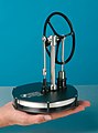
This model runs with the warmth of the hand


literature
- Reinhold Bauer, Failed Innovations: Failures and Technological Change , Campus Verlag, 2006, pp. 194 ff. ISBN 978-3-593-37973-9 .
- Martin Werdich, Kuno Kübler: Stirling machines. Basics - Technology - Application , Ökobuch-Verlag, ISBN 3-922964-96-6 (11th edition 2007) - Introduction to the topic with a description of many designs and applications.
- Fritz Steimle, Jürgen Lamprichs, Peter Beck: Stirling-Maschinen-Technik , CF Müller-Verlag, ISBN 3-7880-7773-5 (2nd edition 2007) - basics, concepts, developments, applications
- Frank Schleder: Stirling engines - thermodynamic fundamentals, cycle calculation, low temperature and free piston engines. Vogel, Würzburg 2008, ISBN 978-3-8343-3116-8 .
- Brent H. Van Arsdel: Around the world by Stirling engine - environmentally friendly Stirling engines, their applications worldwide and into space. American Stirling Co., San Diego 2003, ISBN 978-0-9713918-0-2 .
- Ivo Kolin: Stirling engine - history, theory, practice. Zagreb Univ. Publ., Dubrovnik 1991.
- Colin D. West: Principles and Applications of Stirling Engines. Van Nostrand Reinhold, New York 1986, ISBN 0-442-29273-2 .
- Gustav Schmidt : Theory of Lehmann's caloric machine , in: Journal of the Association of German Engineers , 1871 Volume XV Issue 1 January issue pages 1–12 to Table III and Issue 2 February issue pages 97–112.
- Dieter Viebach: "The Stirling engine simply explained and easily built" , Ökobuch-Verlag, ISBN 978-3-936896-31-2 (8th improved edition 2009) Introduction to the Stirling engine technology, a 0.5 kW experimental engine presented, construction plans for 3 models without turning or milling work for students and trainees.
- Bernward Janzing : power plant in the basement . In: Der Spiegel . No. 48 , 2006 ( online ).
Web links
- Explanation of how it works with animations
- The Stirling engine past and present
- Stirling engine as a water pump in the third world
- Click the “Stirling” item on the building instructions and explanation of the Stirling engine with beer cans
- Explanation of the Stirling cycle using an applet
- Construction exercise with explanations (mechanical engineering, University of Kassel, 1998–2004)
- Video: Stirling engine: cycle, closed system . oncampus GmbH, Lübeck University of Applied Sciences 2012, made available by the Technical Information Library (TIB), doi : 10.5446 / 18624 .
Individual evidence
- ↑ Dieter Viebach: The Stirling engine : simply explained and easily built , Ökobuch-Verlag, ISBN 3-922964-70-2 (1st edition 1998), p. 82.
- ↑ Stirling engine 1816 . In: hotairengines.org .
- ^ Bauer, p. 194 ff.
- ↑ Günter P. Merker, Rüdiger Teichmann (Ed.), " Basics of Combustion Engines ", Springer Fachmedien Wiesbaden, 7th edition 2014, section " 19.3.1 Alternative Concepts ", ISBN 978-3-658-03194-7
- ↑ The Stirling in heat generation ( Memento from January 21, 2015 in the Internet Archive ) (PDF; 682 kB)
- ↑ stirling-und-mehr.de
- ↑ senertec.de ( Memento from August 11, 2011 in the Internet Archive )
- ^ CM Hargreaves: The Philips Stirling Engine . Elsevier Science , 1991, ISBN 0-444-88463-7 .
- ^ Development of Advanced Stirling Radioisotope Generator for Space Exploration. ( Memento from June 5, 2009 in the Internet Archive ) (PDF) NASA (English)
- ↑ MSL Shift and New Energy Sources. raumfahrer.net, January 9, 2009
- ^ Roland Haubrichs: Landfill gas utilization by means of Stirling engines . In: Treatment and recovery of landfill gas - The new guideline VDI 3899 Part 1 . Air cleanliness commission in the VDI and DIN - KRdL standards committee, KRdL series of publications Volume 50, ISBN 978-3-931384-81-4 , pp. 75–84.