
holography

Under holography (also holography , from ancient Greek ὅλος holos , German `` whole '' , `` complete '' and graphics ) one summarizes processes that use the wave character of light (namely its interference and coherence possibilities) in order to create systematically clear representations to achieve that go beyond the possibilities of classical photography (mathematically speaking, a three-dimensional object is reconstructed from a two-dimensional image of its Fourier transform , whereby the angle of view is important). When viewed, the motifs seem to float freely in space. When moving sideways, it is also possible to look around an object and a completely three-dimensional impression is created when viewing with both eyes .
Holographic processes are also increasingly being used in measurement technology, for example in electron microscopy . A hologram ( ancient Greek γράμμα gramma , German 'written' , 'message'), also memory image , is a photographic recording made with holographic techniques , which after elaboration and illumination with coherent light reproduces a real three-dimensional image of the original object.
The crucial ideas about holography, including the term, were coined in 1947 by the Hungarian engineer Dennis Gábor , who was looking for a way to improve electron microscopes, at a time when coherent radiation sources were not easy to manufacture because the laser did not yet exist. Gábor received the Nobel Prize in Physics for his work in 1971 .
The historical development
The physicist Dennis Gábor is considered to be the "inventor" of holography . Its discovery in 1947, however, was not originally intended to be used to depict objects in three dimensions, but to improve the resolution of microscopes .
As early as 1920, the Polish physicist Mieczysław Wolfke wanted to divide the microscopic image into two stages by first generating an intermediate image with short-wavelength rays (e.g. X-rays ). In the second stage, you should be able to view the intermediate image with normal light. But the realization failed at that time due to experimental difficulties. It was only 28 years later that Dennis Gábor was able to unconsciously lay the foundation for holography with a model experiment to implement the two-stage imaging process. His particular merit was to have shown how the information about the phases of the intermediate image can be obtained directly and photographically captured by superimposing the wave emanating from the object and a reference wave.
Gábor attempted to record the hologram of a small 2 mm² slide. On it were the names of three physicists: Christiaan Huygens , Thomas Young and Augustin Jean Fresnel . However, his options at the time were limited because he had to use a mercury vapor lamp as a light source , for example . He had to work with the help of a color filter and a pinhole to increase the coherence , which in turn resulted in an enormous loss of intensity. Its recording setup is known as the "in-line method", since all elements are built up in a row. He only used a single beam of light. He was still working without reference and object waves. The slide he used was transparent with the exception of the black letters. The light is bent at the edges of the letters, the coherent background, which enables interference in the first place, comes from the transparent areas.
The result was less satisfactory because the three names of the original were difficult to recognize and the hologram was disturbed by many dark spots. What surprised him was the creation of a second image, which had a disruptive effect on the viewing as it was superimposed on the actual image. This second image is also called a pseudoscopic or real image, since it shows all concave curvatures of the object in a convex manner and, conversely, all convex curvatures concave.
After the publication of his research work in 1949 and 1951, he turned his back on this area of research in disappointment because he himself was dissatisfied with its results.
In 1959, Gábor was surprised to find out that the two American scientists Emmett Leith and Juris Upatnieks had succeeded in producing good three-dimensional images of objects, the manufacture of which was largely based on Gábor's theoretical foundations. They introduced the two-beam method to avoid the double image problem. Now you could examine the virtual image behind the film separately from the real image in front of the film. When a year later the first laser by Theodore H. Maiman invented (a ruby crystal laser ) and 1963, the He-Ne laser , began the renaissance of holography. In 1963 E. Leith and J. Upatnjeks successfully carried out holographic experiments. Suddenly Gábor's invention, for which no future had been seen before, gained a new reputation and attracted interest especially in the sixties and seventies.
In 1971 Gábor was awarded the Nobel Prize in Physics for his discoveries , 23 years after the invention of holography.
chronology
- In 1947 Dennis Gábor developed the principle of holography, originally with the intention of improving the resolution of electron microscopes . At first he was dependent on the use of filtered light sources and worked with the principle of in-line holography .
- 1960 Invention of the laser by Theodore Maiman .
- 1963 Improvement of the imaging techniques by Emmett Leith and Juris Upatnieks by splitting the imaging arrangement into separate object and reference beams.
- 1964 Production of the first hologram by Leith and Upatnieks ("Train and Bird").
- 1965 Invention of white light holography by Juri Nikolajewitsch Denisjuk .
- 1965 Invention of holographic interferometry by Karl A Stetson and Robert L Powell and other research groups.
- 1967 A ruby pulse laser makes a person's first hologram possible.
- From 1967 Computer Generated Holography (CGH), also known as synthetic holography, is developed by BR Brown , Adolf Lohmann and others.
- From 1967 Digital holography: Joseph W. Goodman and RW Lawrence record holograms of two-dimensional structures with image sensors (vidicons) and then reconstruct them numerically.
- Kronrod, Merzlyakov and Yaroslavskii digitize photographically recorded holograms and reconstruct them with the computer (English-language publication 1972).
- 1968 Stephen A. Benton invents rainbow transmission holography .
- 1971 Awarded the Nobel Prize in Physics to Dennis Gábor for the invention of holography.
- 1978 Nils Abramson invents light-in-flight holography.
- 1993 Digital holography: Ulf Schnars and Werner Jüptner record holograms of macroscopic objects directly with CCD sensors and reconstruct them numerically.
- Since approx. 1990 use of holograms as authenticity certificates on product packaging, books, banknotes and identity cards.
- from 1999 holographic memories are developed.
Physical basics
In black and white photography , only the intensity of the incident light is stored on the film. In color photography you also record the color, i.e. the frequency of the light.
With holography, the phase and intensity are now saved. This is done with the help of interference . In order to create precise interference patterns, one uses coherent light , usually a laser beam that has been expanded by means of scattering lenses.
admission

If you illuminate any object with coherent light, the light is reflected and scattered. A wave field is created that can be perceived with the eyes. This wave field is called the object wave . The object wave is superimposed on the incident, unscattered light (the so-called reference wave ) from the same laser, i.e. i.e., the wavefronts interfere with one another. The resulting interference patterns hit a glass plate or a film on which a light-sensitive layer is located. The layer only reacts to the intensity of the light, but due to the interference of the wave fronts the relative phase (between the object and reference waves) is recorded.
The prerequisites for recording holograms are the temporal and spatial stability of the interference patterns formed by the superposition of the wave fields. The objects to be recorded must not move during the exposure time, which sometimes takes minutes. In order to be able to record a hologram, the parts of the recording apparatus and the object must therefore be spatially fixed. Usually the complete holographic structure or at least parts of it is mounted on a vibration-free table. Such a table has a large mass, often several tons of concrete or heavy stone slabs, on mechanically or pneumatically damped feet. However, pulsed lasers can generate such an intense beam of light for a short time that a hologram can be recorded in a few nanoseconds. In this case, the vibrations will not affect the image quality.
If you now develop the film, the exposed areas become black, so there is an interference pattern of black lines; nothing is recorded in between, so only the transparent film can be seen. The lines are very close together and a normal photo film would not be able to record such fine structures. They cannot be seen with the naked eye.
reconstruction
During the reconstruction, the holographic photo plate is illuminated with a wave that is identical to the reference wave. The light is bent at the interference pattern, and the exact wave front of the object wave is created. Behind the hologram (looking towards the photo plate and light source) you can see the depicted object as if through a window. This is why such holograms are also called transmission or backlight holograms because the laser and the viewer are on different sides.
Since the entire wave field in front of and behind the recorded object is also reconstructed, the eyes can see the image from slightly different directions (interpupillary distance). This enables the brain to create a spatial impression. This is further enhanced by the fact that one can even move back and forth in the wave field and thus see the object from different directions and, to a limited extent, also around it.
Each point of the depicted object influences the wave pattern of the entire holographic image carrier. So if a hologram is cut up, the whole image is still created during the reconstruction. Dividing the hologram into individual pieces only leads to a deterioration in the resolution of the image and to a reduction in the spatial angle of view that can be viewed.
Hologram types
In general, holograms can be divided into volume and area holograms, as well as amplitude and phase holograms, according to the properties of the film. Depending on the colors that occur during the reconstruction of the holographic images, a distinction is made between white-light holograms and holograms that cannot be reconstructed under white light, and real-colored holograms.
Volume hologram
Volume holograms are located on a film, the thickness of which is also used to store holographic information. Only volume holograms can be white light holograms, because because of the Bragg condition, interference that is selective for the wavelengths of the light takes place in this case.
Only if the Bragg equation is fulfilled can the light incident at an angle with the wavelength be reflected on the film with the lattice plane spacing. In the case of white light reflection holograms, the color of the hologram therefore depends on the angle of incidence of the light on the film.


True color holograms can be made using white light lasers. White laser light can be generated by additive color mixing of the three basic colors red, green and blue. The holographic film must be sensitive to all colors in real-color holograms, which is not achieved by most commercially available films. When reconstructing true-color transmission holograms, it must be noted that the light with different wavelengths and colors is diffracted to different degrees. The lasers used for the reconstruction must therefore have a certain angle to the film, depending on the respective wavelength, so that the individual red, green and blue images are created in the same place. As an alternative to using a white light laser, holographic films can also be exposed one after the other with the three colored lasers. In a variant of multiple exposure, it is also possible to use film material that is only sensitive to one wavelength. This makes use of the fact that the wavelength reflected during the reconstruction deviates from the wavelength used for recording when the film layer changes its thickness after the recording. To this end, the film is left to e.g. B. swell in a solution with a defined concentration of triethanolamine . This can be repeated with different concentrations before each further exposure. The film shrinks again when it is developed, so that several wavelengths are reconstructed when illuminated with white light.
Amplitude hologram
Amplitude holograms are located on films that have different degrees of blackness. This changes the brightness of the transmitted light in such a way that the superimposition of the light waves with different amplitudes and phases creates an image. In contrast, the films of the phase holograms have the same transparency everywhere . The interference pattern that generates the holographic images then only comes about through the different phases of the electromagnetic waves. Phase holograms can therefore be formed by surface reliefs, i. H. from a pattern of depressions and elevations. Then the light rays travel different paths in the film material, which is mostly made of plastic film. The speed of light propagation in the film is slower than in air, which is why different light paths covered in the film lead to phase differences. This is what the interference in phase holograms is based on. Phase holograms are often embossed holograms in which the depressions are pressed into the material with a stamp; However, even with special films, depressions can arise from different exposure. In addition to the possibility of phase modulation through surface reliefs, a phase hologram can be achieved through local modulation of the refractive index such as e.g. B. in silver halide films.

Recording of a transmission hologram
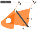
Recording of a reflection hologram

Recording of a Denisjuk hologram


Legend:
1: Laser
2: Mirror
3: Beam splitter
4: Diffusing lens
5: Reference beam
6: Object beam
7: Holographic film
Transmission holograms
Transmission holograms are on translucent films; that is, they transmit the light. During recording, part of the laser beam hits the film unchanged as a reference beam, the other part hits the object and is reflected by it onto the film. The reference beam and the object beam hit the film from the same side and there generate an interference pattern that is recorded.
For the reconstruction of the image, the transmission hologram has to be illuminated from behind with a coherent light source. If, however, a developed transmission hologram is only exposed to the reference beam, the angle of which corresponds to that when the hologram was recorded, then on the non-illuminated side of the film the interference pattern creates diverging rays that correspond to the elongation of the object rays during the recording. Because of these diverging rays, a virtual image appears behind the hologram, i.e. on the illuminated side. At the same time, a real image is created in front of the hologram, because the diffracted light waves also create converging rays. A ray of the virtual image as an extension of the original object ray and a ray of the real image emanate from each pixel on the hologram, the two rays having the same angle to the film. The two images can therefore only be seen from different angles, they can also partially overlap. Every point of the real image has the same distance to the film as the corresponding point of the virtual image. In the real image, the points close to the original object therefore appear distant, the distant points appear to be in front in the image. This inversion is called pseudoscopy , while the virtual image shows the true distances and is therefore called orthoscopic .
Reflection holograms
Reflection holograms reflect the incident light so that, in contrast to transmission holograms, the light source can be on the side of the viewer. With reflection holograms, the laser beam is split with beam splitters . One part of the beam hits the holographic film as a reference beam after it has been fanned out with a scattering lens , the other beam is directed onto the object. This reflects the light beam on the other side of the film. The object beam and reference beam hit the film from different sides and form an interference pattern in it that exposes the film. Reflection holograms are in any case volume holograms, i.e. That is, the thickness of the recording material is used to store the holographic image. Various network planes arise in the film , which go through the areas of the film material exposed at the interference maxima. During the reconstruction of the hologram, the network planes reflect the incident light back in such a way that an image of the object is created. Because of the Bragg condition, reflection holograms are white light holograms.
Denisjuk holograms

In 1963, the Soviet physicist Yuri Nikolajewitsch Denisjuk invented a simpler method of making reflection holograms. With Denisjuk holography, in contrast to normal reflection holography, the laser beam is not split. The laser beam is fanned out by a convex lens and shines through the holographic film as a reference beam. Behind the film is the object to be recorded, which partially reflects the reference beam back to the film. The resulting object beam and the reference beam hit the film from different sides and interfere, creating a static electromagnetic wave field in it that is picked up by the film. Denisjuk holograms, like all reflection holograms, can be reconstructed under white light.
Image plane holograms
Image plane holograms are reflection holograms and have the property that their holographic images appear to float in the film plane. This effect is based on the fact that the image is created both in front of and behind the hologram plane.
For production, a transmission hologram (master) must first be recorded from an object, which is then copied onto the film of the image plane hologram. For this purpose, the recorded master hologram is reconstructed under monochromatic light. The image plane film is placed in the real image of the master and additionally illuminated with a reference beam.
After exposure, the hologram can show an image on each side of the film virtually and real at the same time. The virtual image is created by extending the diverging rays and is therefore behind the film; the real image is in front of the film. The impression is created that the image is partly behind and in front of the film because one sees the real and virtual image at the same time.
Rainbow holograms
Rainbow holograms are also reflection holograms and, like image plane holograms, are produced with the help of a master. The object is recorded as a transmission hologram (master) and this is reconstructed. The film for the rainbow hologram is now placed in the virtual image of the master. The master is covered in such a way that only a small, horizontal gap lets light through. Because of the narrow gap, the rainbow hologram lacks spatiality in the vertical direction. Because the spectral colors of the light are more strongly diffracted with longer wavelengths , the rainbow hologram appears like a rainbow in the color transitions from red to blue. If you look at the rainbow hologram under monochromatic light, only a small section of the image can be seen.
Multiplex holograms
Multiplex holograms depict moving images on film. In order to produce them, a video film is first made , from which each image is then holographically copied. The holograms of the video images are recorded in sequence as strips 2 to 6 mm wide on a holographic film. Because the stripes are narrow, they alone do not appear three-dimensional; three-dimensionality only arises through stereoscopic vision . If the viewer looks at the multiplex hologram at another point, he sees the strip holograms of another video image and recognizes the movements recorded with the video. This allows moving images to be recorded in the hologram.
Light-in-flight holography
The condition for the creation of a hologram is that the coherence length of the laser must be greater than the optical path difference between the light path from the beam splitter via the object to the photo plate (object wave) and the path from the beam splitter directly to the photo plate (reference wave). With the light-in-flight (LiF) holography proposed by Nils Abramson , the object is illuminated at a very flat angle. When using a laser with a short coherence length , the coherence condition - the coherence length must be greater than the optical path difference - is no longer fulfilled for all object components for the entire hologram. Different areas of the hologram store the waves emanating from different parts of the object. When looking through different hologram areas, you can see different parts of the object. By continuously varying the observation point, you can see how the wavefront used to illuminate the object slides over the object, as if in slow motion. The time resolution is determined by the coherence time of the laser. In his first experiments Abramson used an argon-ion laser that oscillates without the usual mode-selecting elements (etalons). The laser then has a coherence length of a few centimeters, which corresponds to a coherence time of a few tens of picoseconds. Later, multimode dye lasers with a coherence length of a few millimeters and a coherence time of a few picoseconds were used. In addition to examining the propagation of wave fronts, light-in-flight holography is also suitable for measuring the shape (contouring) of components. Abramson was also able to show interesting connections between the LiF method and the special theory of relativity .
Computer generated holograms
Computer-generated holograms (CGH) have the advantage that they are very precise, many imaging errors are avoided and no object is required for the recording. The calculation of holograms is suitable for mathematically precisely describable forms such as company logos and holographic-optical components. Usually a hologram ( Fresnel zone plate ) is calculated from each point of the object ; these holograms are then superimposed depending on the arrangement of the points. This creates an interference pattern that is transferred from the computer to the production machines. Often stamps are produced from the calculated holograms in order to produce embossed holograms .
Digital holography
The so-called " digital holography " can be described as a continuation of the recording technology. Here the photochemical recording process is replaced by a high-resolution electro-optical camera. The image is then reconstructed digitally, i.e. by numerical reconstruction according to the laws of propagation of light (diffraction theory). Various simplifications to accelerate the calculation process and post-processing steps allow a complete, three-dimensional reconstruction of the object. This method is often used in holographic microscopy.
Recording material
Holographic films as conventional films for the photograph of a gel made in which silver halides are. The silver halides break down into silver crystals and free halogens when exposed to light . The finely distributed silver crystals cause the film to blacken at intensity maxima, which are dependent on the interference pattern when the hologram is recorded. This creates an amplitude hologram. As in normal photography, the exposed films are developed in different baths . However, the silver crystals in holographic films must be much smaller in order to enable the necessary resolution. If bleaching processes are used, local distributions of silver halide crystals can be produced which have no absorption but a different refractive index. In this way phase holograms can be developed.
Photoresists (photoresist) change during exposure in such a way that part of them is solidified and the remaining photoresist can be removed. In the case of positive resists, the unexposed areas remain solid; in the case of negative resists, the exposed areas solidify. When the removable portion is removed, only the solid photoresist areas remain as elevations in the holographic film. The elevations and depressions in the film create a relief, which is why phase holograms are created when using photoresists. These films are well suited as templates for stamps used to produce embossed holograms.
Some substances change their refractive index depending on exposure because of the photorefractive effect . Examples of photorefractive recording materials are lithium niobate , barium titanate and gallium arsenide .
Dichromate gelatine enables high resolutions and enables very bright transmission and reflection holograms. The material is most sensitive to purple to green light and does not respond to red light. A sensitization to red light, by the addition of dyes can be achieved. Dichromate gelatine requires a high light intensity for exposure. It is also very sensitive to environmental influences such as temperature fluctuations and humidity, but holograms of very high quality can be produced. The humidity damages the dichromated gelatin, are therefore has the hologram sealed by the film to a glass plate bonded is.
In the case of photopolymers, the polymerization is caused by exposure to light. This changes the optical properties such as the refractive index, and a hologram is created. The photopolymers are held in place by illuminating them with an incoherent light source. Photopolymers are suitable for the production of transmission and reflection holograms.
Applications
Holographic Optical Components (HOE)
Holographic-optical components are elements whose holographic properties are used for the optics of devices. Conventional lenses , mirrors and prisms can be replaced with holograms ; however, the additional holographic properties are often of particular advantage. The simplest holographic component is the Fresnel zone plate , which is also called a zone lens because of its properties. A zone lens is the hologram of a point and therefore acts as a transmission hologram at the same time as a convergent lens when the real image is viewed and a divergent lens when one starts from the virtual image. HOEs have special properties such as the selectivity of color and the angle of incidence of light. The components can, for example, refract the light for a certain angle of incidence, but be completely transparent for the others. The different diffraction of light depending on its wavelength enables it to be split into spectral colors like prisms. With the help of reflection holograms, it is possible to construct planar mirrors, concave mirrors or curved mirrors which, for example, reflect the light in such a way that the angle of incidence is different from the angle of reflection.
HOEs are used in barcode scanners , laser scanners and in head-up displays . For example, the IBM Model 3687 bar code scanner contains holograms made from dichromate gelatine to read codes faster and more reliably. The advantages of HOEs are that, in contrast to conventional optical elements made of glass or plastic, they are lighter, because of the unnecessary curvature, they are much flatter and at the same time very transparent and precise. However, the holograms are still relatively expensive and more sensitive compared to the glass elements.
HOEs can also influence other spectral ranges of the electromagnetic waves. Either the holograms are produced for this by exposure to, for example, X-rays on a suitable film, or the interference patterns of holograms selective for visible light are changed by swelling agents in such a way that their selectivity shifts into other spectral ranges.
Certificates of Authenticity


To protect against counterfeiting , most banknotes and passports have holograms or kinegrams printed on them because they are very difficult to copy. This technique is also used for tickets to sports and music events. Holograms and kinegrams are often confused; Holograms show 3D images (e.g. on EC or credit cards), while kinegrams show 2D motion sequences with changing viewing angles.
Processes are being developed in which holograms are embossed into steel components with explosives to protect against forgery .
medicine
In medicine , research is being carried out on methods for three-dimensional facial profile measurement using holography. During operations on the face, careful planning is necessary, for which the face must be measured. Conventional procedures have proven to be time-consuming and imprecise due to the involuntary movements of the patient. Holograms of faces, which are recorded with pulsed lasers in 25–35 nanoseconds, provide exact information about the dimensions and spatial depth of the face. In order to transfer the data to the computer, a camera recording is made of each spatial level of the holographic image. The resulting sectional images can be put together and analyzed on the computer. Holographic endoscopy, which is currently being developed, is also of importance for surgical interventions .
Holographic endoscopy
With holographic endoscopy it is possible to transfer spatial images from inside the body or from hard-to-reach places in machines. The most important advantage compared to conventional endoscopy, however, is the possibility of integrating interferometric measuring systems into the endoscopes. This enables vibrations and deformations in components or in medicine on organs to be made visible. Pulsed lasers are used for holographic endoscopy; That is to say, a high temporal resolution of the images can also be achieved. The Institute for Technical Optics at the University of Stuttgart has already developed prototypes for these endoscopes.
archeology
With holographic recording devices it is possible to create holograms of archaeological finds. The holograms can then be further processed on the computer. There is no need to transport the found objects, which represents a risk of damage. The evaluation of the holograms can take place at a different location because they contain all spatial information about the objects. In addition, the images of several fragments, for example clay pots, can be put together on the computer. At the University of Münster , for example, very high-resolution and true-color holograms are created from old cuneiform tablets in order to put them together on the computer and to increase their readability. The caesar took among others, a 2000 year old bog body holographically on to reconstruct the face later.
Holographic interferometry
With the help of holographic interferometry it is possible to measure the smallest deformations or movements of objects. Three different methods are used:
In the double exposure process , a hologram is recorded on the same film of an object before and after it is deformed. The unchanged points of the object cause the same exposure on the film in the two shots, which is why it is exposed more strongly in the corresponding places.
With the time averaging method ( time average holography), a moving object is recorded as a hologram during the change process. You can use it to make vibrations visible by taking advantage of the fact that a vibrating object stays longer at its reversal points than at the other points. The method is used to optimize sound bodies in musical instruments, to minimize noise in engine production and to eliminate vibrations in precision machines.
The real-time method makes it possible to observe the deformations of an object in real time. To do this, a hologram of the object is first made before the change. The superimposition of the original hologram with the image of the changed object creates interference fringes. These can also be evaluated quantitatively and thus provide information about the smallest deformations in the order of magnitude of the light wavelength used. For example, thermal expansion or vibrations in mechanical systems can be measured.
Holographic interferometry is used, for example, to compare tire shapes at different pressures. The measurement method is well suited for vibration analysis, because the wavelengths can be determined by measuring the blackening on the holographic film. The deformations of z. B. aircraft wings and other components under heat or load can be visualized with the double exposure process or the real-time process. With the double exposure process, the growth rate of mushrooms can be determined in just a few seconds, so that the nutritional requirements for mushroom cultures can be calculated.
However, holographic interferometry based on holograms stored on film material is almost only used in the laboratory, since the recording and development process is very prone to failure and takes a relatively long time. Instead, further developments are used: In electronic speckle interferometry (see also electronic speckle pattern interferometry ), images of the objects to be examined are superimposed with the reference wave in the image plane so that the spatial frequencies resulting from the interference can be recorded with a CCD sensor. The correlation of interferograms recorded in different load conditions then results in similar stripe patterns as in holographic interferometry. An evolution (or variant) of the ESPI process is the Shearography . This method is very robust with regard to vibrations, since the interfering partial waves are both guided over the object. Finally, digital holography (see above) is also used for interferometric measurement of deformations.
X-ray holography
At the Berlin synchrotron BESSY , scientists have succeeded for the first time in recording holograms of nanostructures . Intensive X-rays were used for this. The magnetic domains could be imaged in a cobalt - platinum film with a resolution of 50 nanometers . Since X-rays with a considerable coherent portion in the form of synchrotron radiation are increasingly available from specially built synchrotron radiation sources and especially from free-electron lasers , X-ray holography is becoming increasingly popular as a high-resolution imaging method.
art
Holography is also widespread in art because of its fascinating spatial representation . Lloyd Cross co-founded the first holographic school in California in 1971 . In 1978 Steven A. Benton created one of the most formative rainbow transmission holograms of the time. It bears the title “Rind II” and, based on MC Escher, shows a human head made from a flat ribbon. Museums emerged such as the Holarium in Esens ( Lower Saxony ) in Germany and the Museum of Holography in North Rhine-Westphalia . The Museum for Holography in Pulheim , founded by Matthias Lauk , has been the center of the German holographic scene for many years. The former “Lauk Collection” is now located in the LVR-Landesmuseum Bonn , where it is only occasionally shown for conservation reasons. The holograph Detlev Abendroth founded the AKS-Holographie Galerie in Essen as early as the 1980s .
Holographic art is a form of media art . The Center for Art and Media Technology (ZKM) in Karlsruhe has one of the largest collections of artistic holography in Europe.
Other uses
The conoscopic holography is an optical measuring principle for the contactless measurement of shape deviations.
Holographic memories are available for analog image data or digital data. Digital information is recorded as a two-dimensional bit pattern.
literature
- Fred Unterseher, Jeanenne Hansen, Bob Schlesinger: Handbook of Holography . Popa-Verlag, Munich Frankfurt 1991, ISBN 3-925818-01-4 .
- Joseph E. Kasper: The complete book of holograms - how they work and how to make them . Dover Publ., Mineola 2001, ISBN 0-486-41580-5 .
- Wolfgang Demtröder: Experimental Physics 2. Electricity and Optics . 3rd, revised and expanded edition. Springer, Berlin Heidelberg New York 2004, ISBN 3-540-20210-2 .
- Ernst Peter Fischer: Laser - A German success story from Einstein to today . Siedler, Munich 2010, ISBN 978-3-88680-946-2 .
- Gerhard K. Ackermann, Jürgen Eichler: Holography: A Practical Approach . Wiley-VCH, Berlin 2007, ISBN 978-3-527-40663-0 .
Web links
- Touchable holograms from 3Daround (Bonn) ( Memento from November 9, 2012 in the Internet Archive )
Individual evidence
- ↑ D. Gabor: A new microscopic principle. Nature 161, 1948, pp. 777-778
- ^ D. Gabor: Microscopy by reconstructed wavefronts. Proc Roy Soc 197, 1949, 454-487
- ^ D. Gabor: Microscopy by reconstructed wavefronts: 2. Proc Phys Soc 64, 1951, 449-469
- ^ TH Maiman: Stimulated Optical Radiation in Ruby. Nature 187, 1960, 4736, 493-494
- ↑ E. Leith, J. Upatnieks: Reconstructed wavefronts and communication theory. Jour Opt Soc Amer 52, 1962, 1123-1130
- ^ E. Leith, J. Upatnieks: Wavefront reconstruction with diffused illumination and three-dimensional objects. Journ Opt Soc Amer 54, 1964, 1295-1301
- ↑ Yu N Denisyuk: On the reproduction of the optical properties of an object by the wave field of its scattered radiation II. Optics and Spectroscopy 18, 1965, 152-7
- ^ RL Powell, KA Stetson: Interferometric vibration analysis by wavefront reconstruction. Journ Opt Soc. Amer 55, 1965, 1593-1508
- ^ KA Stetson, RL Powell: Interferometric Hologram Evaluation and Real-Time Vibration Analysis of Diffuse Objects. J. Opt. Soc. At the. 55, 1965, 1694-1695
- ↑ R. Brooks, LO Heflinger, RF Würker: Interferometry with a holographically reconstructed comparison beam. Applied Physics Letters 7, 1965, 248-9
- ^ RJ Collier, ET Doherty, KS Pennington: The application of Moire techniques to holography. Applied Physics Letters 7, 1965, 223-5
- ^ KA Haines, BP Hildebrand: Contour generation by wavefront reconstruction. Physics Letter 19 (1), 1965
- ↑ L D. Siebert: Front lighted pulse laser holography. Appl. Physics Letters 11, 1967, 326-8
- ^ BR Brown, AW Lohmann: Computer-generated Binary Holograms. IBM Journal of Research and Development, Volume 13, No. 2, March 1969, pp. 160-168
- ^ JW Goodman, RW Lawrence: Digital image formation from electronically detected holograms. Appl Phys Lett 11, 1967, 77-79
- ↑ MA Kronrod, NS Merzlyakov, LP YAROSLAVSKII: Reconstruction of holograms with a computer. Sov Phys-Tech Phys USA 17 (2), 1972, 333-334
- ^ SA Benton: Hologram reconstruction with extended incoherent sources. J. Opt. Soc. On 59, 1969, 1545
- ↑ N. Abramson: Light-in-flight recording by holography. Opt. Lett. 3, 1978, 121-123
- ↑ U. Schnars: Digital recording and mathematical reconstruction of holograms in interferometry. VDI Progress Reports Series 8, No. 378, VDI, Düsseldorf, see https://sites.google.com/view/ulfswebsite/
- ↑ U. Schnars, W. Jueptner: Direct recording of holograms by a CCD target and numerical reconstruction. Applied Optics 33 (2), 1994, 179-181
- ↑ https://www.heise.de/newsticker/meldung/Tesa-ROM-wird-kommerziell-entwickelt-14332.html
- ^ Gerhard K. Ackermann, Jürgen Eichler: Holography: A Practical Approach . Wiley-VCH, 2007, [1]
- ↑ N. Abramson: Holography and Relativity. In "Holography for the New Millennium," Ed. J. Ludman, H. Caulfield, J. Riccobono, Springer 2002, 281-300
- ↑ Holograms as a seal of authenticity blown into steel . welt.de
- ↑ Jens R. Bongartz: High-resolution three-dimensional face profile measurement with short-pulsed holography . Faculty of Mathematics and Natural Sciences, Heinrich Heine University Düsseldorf, 2002 ( Online [PDF; 10.2 MB ; accessed on January 23, 2018] dissertation).
- ↑ Giancarlo Pedrini: Pulsed digital holography for vibration measurements on surfaces that are difficult to access. In: Institute for Technical Optics, University of Stuttgart. 2004, accessed January 23, 2018 .
- ↑ State-of-the-art holography technology revolutionizes archeology. In: Wissenschaft.de. November 15, 2000, accessed September 8, 2019 .
- ↑ Holography combines medicine and archeology
- ^ T. Kreis: Handbook of Holographic Interferometry . Wiley-VCH, 2004, wiley-vch.de
- ↑ U. Schnars, C. Falldorf, J. Watson, W. Jüptner: Digital Holography and Wavefront Sensing (Second Edition) . Springer, 2014, ISBN 978-3-662-44692-8 , [2]
- ↑ S. Eisebitt et al., Nature vol. 432, 885 (2004), doi : 10.1038 / nature03139
- ↑ Holarium - Museum of Holography. Archived from the original on June 23, 2002 ; Retrieved January 23, 2018 (early version, latest version: 2013-10-05).
- ^ Maria Machnik: Holografie-Museum: Matthias Lauk has died. In: Kölner Stadt-Anzeiger. December 9, 2009, accessed on January 23, 2018 (obituary for founder, museum closed since 2010).
- ↑ AKS Holography Gallery. Retrieved January 23, 2018 .