
Driverless transport vehicle
A driverless transport vehicle ( FTF , English Automated Guided Vehicle , AGV ) is a floor-bound conveyor with its own drive that is automatically controlled and guided without contact. Driverless transport vehicles are used to transport materials , namely to pull or carry goods with active or passive load handling equipment .
Driverless transport systems (AGV) are in-house, floor-bound conveyor systems with automatically controlled vehicles whose primary task is to transport materials, but not to transport people. They are used inside and outside of buildings and essentially consist of the following components:
- one or more driverless transport vehicles
- a master control
- Facilities for determining the location and recording the situation
- Data transmission facilities
- Infrastructure and peripheral facilities
Both definitions are taken from VDI guideline 2510 "Driverless transport systems".
An automated guided vehicle is subject to the Machinery Directive in the European Economic Area.
Motivation for the use of driverless transport systems
For many years there has been a demand for short lead times, low stocks and high flexibility in production and distribution companies. Various organizational measures and the use of technical means are possible or necessary to achieve these goals. In the area of technical-operational logistics , it is the processes and resources of the internal material flow that have to be designed appropriately. An important process in the flow of materials is the transport , i.e. the targeted change of location of goods. A resource that is used for this purpose in almost all companies because of its universal application possibilities is the conventional forklift or its "little brother", the pallet truck ("ant").
In addition to many undisputed advantages, manual transport also has disadvantages, which is why there are automation solutions for the internal transport of goods. Automated transport offers the following advantages compared to manual transport:
- Organized material and information flow leads directly to productivity-increasing transparency of internal processes
- Punctual and predictable transport processes at all times
- Minimizing fear stocks and waiting stocks
- Reduction of personnel retention in transport, thereby lowering personnel costs (especially in multi-shift operations)
- Minimization of transport damage and incorrect deliveries, thereby avoiding follow-up costs
- high availability and reliability
A very important criterion, albeit difficult to determine in terms of value, is flexibility, i.e. the ability of a transport system to easily adapt to changed external conditions. A driverless transport system is one of numerous possibilities to automate the transport process, but offers the advantage of the greatest flexibility compared to all other technologies.
Advantages of using AGV
The various conveyor systems differ in terms of their technical properties and capabilities in many ways. Among the automated transport systems, driverless transport systems are seen as a solution with the greatest possible flexibility. To assess the degree of flexibility of a funding system, u. a. the following criteria are important:
- Ability to integrate into existing structures
- Transport of various goods
- Possibility to change the layout
- Movability of the conveyor system
- Adaptation to fluctuating transport performance requirements
- Change in the order of funding
- Adaptation to a growing degree of automation
An automated guided vehicle system fulfills all of these criteria.
Further positive features of an AGVS, which in individual cases - but not as a whole - can be exceeded by other funding sources:
- Improvement of the working environment: safer and more pleasant working conditions through orderly processes, clean and quiet transport processes
- high precision with automatic load transfer and acceptance
- minor infrastructure measures
- easy realization of crossings and branch points
- Transport outside of halls possible
- Multiple use of the funding level is possible
- Use of a replacement means of conveyance (e.g. forklift truck)
- Suitable for both low and high room heights
- high transparency of the funding process
- usually no additional traffic space required
- Use of existing driveways
- Indoor and outdoor use possible
- various additional functions can be integrated
Application areas for AGV

The areas of application for driverless transport systems are as diverse as the transport tasks in industry; In principle, there are no implementation restrictions for AGVs.
The following table gives an overview of key figures and properties of systems implemented so far:
| property | typical values |
|---|---|
| Number of AGVs per system | one to several hundred |
| Load capacity of an AGV | a few kilograms to over 50 t |
| speed | typically approx. 1 m / s, other values possible; the maximum speed is limited by the braking power |
| Route length | a few meters to over 10 km |
| Number of load change / work stations | unlimited |
| Plant control | manual to fully automatic, stand-alone or integrated into complex material flow systems |
| Duration of use | sporadically to "around the clock" |
| drive | electric, with or without battery; Internal combustion engine |
Driverless transport systems can be adapted to a wide variety of tasks. The following images of vehicles show the variety of possible applications:
In-house transport
- no or no powered load handling device (LAM)

AGV as undercarriage tractor; Use in the hospital
AGV as undercarriage tractor; Use in the hospital

AGV as undercarriage tractor; Use in the hospital

AGV for driving under and pulling transport trolleys; Use in the automotive industry


- active LAM, standard loading aid
- Vehicles for pallet transport

AGV with 2 roller conveyors for load changes on both sides

AGV with lifting fork for transporting pallets, lattice boxes, racks, etc. Ä.


- Vehicles for KLT transport (small parts load carriers; e.g. "Schäfer-Kasten")

AGV with 2 belt conveyors

AGV with 3 belt conveyors


- Mobile assembly platforms

AGVs as an assembly platform in engine production

AGV as an assembly platform in unit production

AGVs as an assembly platform in engine production

AGVs as a "rolling workbench" in aggregate production

AGVs for body transport in automobile production


Special vehicles
- Heavy-duty AGV for indoor applications, various loading aids
Heavy duty AGV as a side loader

AGV with clamp gripper for paper rolls

AGV with clamp gripper for rectangular cargo

Heavy-duty AGV with laser navigation, max. Total weight 62 to


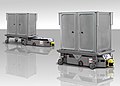
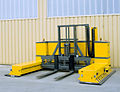
- Vehicles in the outdoor area (so-called outdoor AGV)

Outdoor AGV with 5 pallet roller conveyors
Outdoor AGV with rain protection for the load
Outdoor AGV for transporting concrete blocks
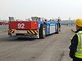
Outdoor AGV with lithium-ion battery in the CTA


AGV in the hospital
The use of AGVs in hospital logistics occupies a certain special position , as this is not an industrial environment in the narrower sense. For this application, another name has been established, namely automatic goods transport with the abbreviation AWT, which in automated hospital logistics includes not only AGV, but also other technologies such as pneumatic tube systems , power & free systems or overhead monorail systems.
History of the AGVS

Around 1953/54, the American company Barrett Vehicle Systems presented a tractor for the first time, which automatically followed a white color stripe applied to the floor. For this purpose, a steering motor was also attached to the steering wheel , which received control signals from an optical sensor with which the color stripe was scanned. These tow trains were used for recurring collective transports over long distances. Vehicles made by EMI in England, which came onto the market there from 1956, worked according to the same principle .
In Germany, the development began in 1963. Manufacturers of industrial trucks, until the early 1980s in particular the companies Jungheinrich in Hamburg and Wagner in Reutlingen, automated fork lift and platform vehicles originally also built for manual operation using "photoelectronic" and later inductive control. Until then, “self-steering”, rail-guided order picking vehicles were converted in the same way.
As early as the late 1960s, tractors specially designed for automatic transport were developed. Equipped with automatic couplings and the ability to automatically reverse, these vehicles could couple trailers and park them where required. Devices for automatic battery charging were also already in place.
The different demands of users from all conceivable industries, branches and service companies stimulated further development. The many degrees of freedom in the structural design of the vehicles led to countless variants in the vehicle structure. Technical and technological developments in electronics , semiconductor technology , computer technology and sensor technology have made increasingly complex controls and systems possible. Developments in material flow and storage technology, production methods in mechanical engineering and trends in assembly techniques, work design, work methodology and ergonomics also had a positive effect.
If a vehicle is to be operated automatically, i.e. without a human driver, navigation is one of the essential tasks that must be solved by vehicle computers + software + suitable sensors. In navigation - originally for ships, but also applies to land vehicles - there are the following tasks:
- Position determination ("Where am I?")
- Course determination:
- depending on the current position and the target to be reached: Determination of the target direction of travel and target speed
- Determination of the actual values: current direction and speed of travel
Selected from the maritime originating method of dead reckoning based on the principle, by measuring the direction and speed or distance traveled from a known starting point starting to calculate the current position. The dead reckoning is a relative method for determining the position; apart from the starting point, it does not use any absolute (fixed) reference points. The advantage of dead reckoning is that it can be carried out with relatively simple measuring devices and algorithms. The disadvantage is that the accuracy or the error of these measuring devices is directly included in the accuracy of the result. As the distance from the starting point increases, this leads to a deterioration in the accuracy of the determined position. Although this principle-related disadvantage can be minimized by laborious calibration of the measuring devices and careful work, it cannot be completely eliminated. Additional errors arise from the influence of unknown, unnoticed or non-measurable disturbance variables.
The dead reckoning in land vehicles is also known as odometry ( Odometer "device for distance measurement" ).
The direction of travel is determined by measuring the steering angle (s) of the vehicle. The distance covered can be determined by counting the revolutions of a wheel whose diameter or circumference is known.
Known problems and possible sources of errors in odometry:
- Accuracy of vehicle alignment at the starting position
- Setting the straight-ahead direction of the wheel or wheels (steering angle measurement value 0 ° does not lead to straight-ahead travel exactly)
- Steering angle zero point "wanders" (changes due to mechanical influences)
- Wheel diameter changes, e.g. B. by wear and tear or different loads
- Wheel slip : locking wheel in the event of an emergency stop, spinning wheel in wet conditions, sliding in a curve driven too fast
Conclusion : odometry alone is by no means sufficient as a navigation method for automated guided vehicles.
Lane guidance with continuous guideline


There are various technical possibilities to improve the results of odometry and to alleviate the disadvantages described above. The problems associated with determining the direction of travel are no longer relevant if the vehicle follows a continuous guideline with suitable sensors . Depending on the operating environment, optical, magnetic or inductive guidelines are used and detected with cameras (color contrast), Hall sensors (magnetic field) or antennas (alternating electrical field).
The second problem of odometry, the accumulating errors in the distance measurement, can be solved by means of reference points along the route: Driving over ground marks (pieces of metal, magnet, transponder ), the distances of which are stored in the vehicle control system, triggers a signal in the vehicle control system , and the path measurement error that has arisen up to this point is zeroed. Any fine positioning of the vehicle that may be required at the target point is also carried out relative to an external trigger signal (floor mark, light barrier, etc.).
- advantages
- method known and proven for many years
- simple, robust and inexpensive components in the vehicles
- disadvantage
- Creating, changing and, if necessary, repairing the guideline requires a great deal of effort
- The type and material of the guideline depends on the nature of the soil; may not be used everywhere
- little to no flexibility when changing course
In order to reduce the costs associated with the creation of the guide track, the continuous guide line can be turned into a discontinuous guide line (a series of support points). This process is known as grid navigation. Grid dots are usually formed by magnets or transponders embedded in the floor, optical grids (e.g. color contrast through "checkerboard pattern") are also possible. The vehicles are equipped with suitable sensors for recognizing the grid points (magnetic sensor, transponder reader, color sensor / camera) and “shimmy” from one grid point to the next.
If - for reasons of cost - the distance between the grid points is to be large, the odometry and, in particular, the straight-line stability of the vehicle must be very well calibrated . A rotation rate sensor ( gyroscope ) is often used for support / improvement to measure the change in the rotational position of the vehicle.
When crossing a grid point, the current position error must be determined, a corrective movement calculated and its correct execution monitored while moving to the next grid point. This requires precise steering angle measurement and control as well as the processing of mathematical algorithms in software, i.e. H. a more complex control is required compared to vehicles with continuous guideline.
With regard to the position (and number) of the grid points, a distinction can be made between the quasi one-dimensional line grid and a two-dimensional surface grid, in which the grid points are arranged in the entire driving plane. Such an area grid - often in the form of a (regular) grid - offers more potential routes for the vehicles compared to the line grid, i.e. H. Future changes to the AGV routes can be carried out more quickly, as the ground work for laying the new / additional grid points is no longer necessary.
- advantages
- method known and proven for many years
- Guide track creation cheaper than with a continuous guide line
- Creation / changes of the lead track possible during operation
- Changes to the lead track are possible with reasonable effort
- suitable for outdoor use
- disadvantage
- depending on the nature of the soil, cannot be used everywhere
- limited flexibility with regard to changes of course
The methods described so far use a so-called physical guideline for driving the vehicle : physical features are installed along the desired route (colored lines, metal strips, wire through which alternating current flows, magnets, etc.) that can be detected and tracked by suitable sensors on the AGV.
If a physical guideline cannot or should not be used, there is an alternative, so-called virtual guideline , which is available in the form of software in the vehicle computer. In this case, however, a not inconsiderable amount of hardware and software must be expended in order to enable a vehicle to reach the desired destination points automatically and with sufficient (repeat) accuracy with the help of this virtual guideline. As with grid navigation, odometry must also be supported by the detection and measurement of absolute reference points. However, these reference points have no relation to the route and in no way describe a guideline.


The device most frequently used in indoor applications to detect and measure absolute reference points is a laser scanner, which is why it is also referred to as laser navigation , or more precisely laser triangulation . The evaluation is based on a z. B. in the seafaring principle, which has been used for a long time, in which optical bearing lines are brought to the intersection on several bearing objects known in their position ( cross bearing ). The goal or result in seafaring is the graphic determination of position in the nautical chart . In the AGV's vehicle computer, the graphic process is replaced by algebra (solving a system of equations with three unknowns). The three unknowns correspond to the vehicle's three degrees of freedom of movement in the driving plane, i.e. the X value, Y value and yaw angle of the current vehicle position (see also the section on chassis, kinematics ).
The measuring system consists of
- the mobile laser scanner mounted on the vehicle (the "direction finder" for angle measurement). The laser scanner consists of a laser diode and receiver, which are located in a motor-driven, rotating head, as well as a high-resolution incremental encoder for angle measurement.
such as
- a practically unlimited number of stationary reference points (the "bearing objects"). The reference points consist of retro-reflective material, the incident laser light is reflected in itself, i.e. to the transmitter or in this case to the receiver mounted directly next to it.
- advantages
- Absolute measuring method with sufficient accuracy and measuring rate for AGV applications
- no effort for creating guide tracks
- high flexibility, changing course changes easily and with little effort
- disadvantage
- Costs for laser sensor (precision measuring device!) And evaluation computer
- Costs for assembly and measurement of the reflector marks
- The floor in the area of the driveways must be relatively flat
- optical measuring method, cannot be used everywhere
refers to a method in which the current vehicle position and direction of travel are obtained by measuring the existing environment, i.e. without additional markings and aids specially installed for the use of the vehicles. Suitable sensors are required for this - for example, 2D or 3D laser scanners or lidar , 2D or 3D cameras - or a combination of several such sensors with which the immediate operational environment of the vehicles can be measured. The measured values obtained are then analyzed using software and a powerful computer. Sensors and evaluation computers are located on or in the vehicle, the evaluation must take place in real time and take into account that the vehicle is moving during the measurements. The measuring rate of the sensors used is approx. 10–20 scans or images per second and a distance and object detail resolution of approx. 1–5 cm is achieved.
A position determination can only be successful if there is a digital map of the operational environment in the vehicle computer, within which the software tries to classify the currently recorded measured values. From the multitude of measured values, those that belong to distinctive environmental features or structures that are contained in the stored map must be filtered out. The map can either be created automatically by the vehicle itself during a learning or orientation drive, in which case it is referred to as SLAM ( Simultaneous Localization and Mapping ). Alternatively, the map can also be built up by manually measuring distinctive features of the surroundings and appropriately processing the measured values obtained in this way. The software algorithms used are able to recognize changes in the operational environment, such as those that can occur constantly during the time the vehicles are in use, as deviations from the stored map information, if necessary to integrate them into the map and, based on this, to continue to determine the current vehicle position and direction of travel determine.
In this way, it is possible to use AGVs in such clearly different environments as factory halls and hospital corridors equally satisfactorily, i.e. with sufficient accuracy and reliability for the respective operation and application.
Further procedures with absolute referencing:
- For outdoor applications with a good (unobstructed) view of the sky (outdoor AGVs, forklifts, van carriers / straddle carriers and container bridge cranes in the port, ...):
- GPS (Global Positioning System), accuracy approx. ± 10 m
- dGPS ( Differential Global Positioning System ), accuracy approx. ± 1 m
- dGPS with phase evaluation, accuracy approx. ± 0.1 m
- For indoor applications or in areas without sufficiently good GPS reception:
- "Indoor GPS"; Depending on the technology used, the ambient conditions and the driving speed, accuracies between approx. ± 2 m and ± 0.5 m can be achieved
With all radio direction finding methods, a certain distance must first be covered to determine the current vehicle yaw angle when using a single receiving antenna, or two receiving antennas with a known position (alignment and distance) must be mounted on the vehicle.
Radio-based location methods are referred to as real-time localization . Abbreviation RTLS (Real Time Localization System) summarized.
Summary
Various technical options are available that allow the current position and direction of travel of an automated guided vehicle to be determined. All of the methods described above have existed for many years and are used successfully in practice. The procedures with a virtual guideline allow relatively more flexibility and thus achieve the advantages mentioned above when using AGVs to a greater extent, but with higher investment requirements.
Differentiation between automatic vs. autonomous driving
The term autonomous driving has been used for some time to describe additional properties that go beyond the previously known and customary capabilities of automatically driving vehicles. In the case of passenger cars, this means driverless driving, i.e. a significant further development of the currently known driver assistance systems. An autonomous car finds its way from its current location to the desired destination independently and without external specifications and is able to react appropriately to all situations and events that arise during the journey.
For driverless transport vehicles, the distinction is primarily based on the type of lane guidance : An AGV is by definition automatically controlled and guided without contact. H. The desired route to the destination is specified using a real or virtual track. It is an autonomously driving / acting AGV if the control of an AGV does not use any of the tracking methods described below, which are all based on the fact that the path from the starting point to the destination is clearly given to the vehicle and without any degrees of freedom that the vehicle can use. An autonomous AGV finds its way from the current location to the desired destination independently and without external specifications, taking into account all situations and events that occur during the journey. The challenge here is to enable the control system to make decisions independently and to select the best one from a multitude of possible solutions to remedy a fault. The degree of autonomy that may arise can be. a. in the route, speed, etc. selected by the AGV, may be different. It depends, for example, on which sensors a vehicle is equipped with for recognizing the surroundings, or what prior knowledge of the operational environment - stored in the form of a digital map in the vehicle computer - the vehicle has. To obtain information about the operational environment, autonomous vehicles can, if necessary, communicate with other vehicles and exchange data in order to improve the results of their decision-making processes. In addition, technologies already exist that enable driverless vehicles to understand human language and gestures as controls.
AGVs that autonomously drive partial sections of a journey to the specified destination, for example when driving around an obstacle that has acutely appeared in the route, can already be found in operational practice. Due to the large amount of measured variables to be recorded and the amount of data to be processed in real time , these vehicles are equipped with extensive sensors, powerful computers and complex software.
Vehicle technology
The picture opposite shows the main assemblies of an automated guided vehicle. They are described in detail in the following sections.
landing gear

Driverless transport vehicles differ on the basis of different chassis concepts with regard to their movement behavior, which is expressed in different envelopes (boundary lines of the area swept by the AGVs) and wheel tracks. The possible movement behavior of an AGV is determined by the number of degrees of freedom of the chassis. A distinction is made between line-moving and area-moving vehicles. Every vehicle basically has three degrees of freedom of movement in its driving plane:
- Translation : movement in the longitudinal and transverse direction
- Rotation : rotation around the vertical axis (the so-called yaw)
In the case of a linearly moving vehicle, these cannot be set independently of one another, since the alignment of the vehicle frame relative to the trajectory is fixed by the chassis. This leads to an increased space requirement when cornering.
In the case of an area-movable vehicle, on the other hand, the orientation of the vehicle frame can be set independently of the vehicle position. All movements (translational and rotational) of the vehicle frame are possible both while driving and from a standstill. Mobile vehicles, however, usually require an increased design and manufacturing effort. Since they have more drives, more extensive control hardware (on-board computer, sensors, actuators, power electronics) and more complex control software are required.
The graphic opposite gives an overview of the most important chassis variants of linear and area-moving transport vehicles.
Various variations of the chassis and wheel arrangements shown are possible. For example, the drive or steering drives can be arranged on one side of the vehicle and the number of drives and wheels can be increased (e.g. to reduce the surface pressure with large loads). However, none of this has any influence on the mobility and the space required by the vehicles.
A clear example of such a variation is the kinematic principle of a car (with an unguided rear axle), which - despite the four wheels - corresponds to three-wheel kinematics in terms of mobility. The different space requirements (the different envelope curve ) when parking backwards or forwards to the side is known to every driver.
Another detail has to be taken into account when it comes to the wheel suspension: Chassis with more than three wheels are generally statically indeterminate! Constructive measures must be taken on the wheel suspension and / or on the vehicle frame in order to ensure that all wheels rest on the ground through elasticity or torsion possibilities.
steering
A distinction is made between the following systems for steering :
- Steering system with a geometric steering angle of the steered wheel (s): Electromechanical or hydraulic steering systems are used that act on steering wheels, which may also be drive wheels.
- Steering systems without a geometrical steering angle, the so-called differential steering: The change in direction of the vehicle takes place here through different speeds of the drive wheels ("tank drive").
- Driving and steering with Mecanum wheels : A Mecanum wheel has a rim on which loose, convex rollers are attached at an angle of 45 ° so that they form an exact circle again over the rolling circumference. The inclined arrangement of the rollers results in two force components when driving the wheel. Forces of the individual wheels directed against one another are compensated for via the axles and the frame. The other forces add up to the resulting direction of travel. In this way, any desired driving maneuver can be generated by appropriately controlling the individual wheels with regard to the direction and speed of rotation. In particular, a movement can begin in any desired direction from a standstill. Vehicles with Mecanum drive achieve extremely high maneuverability, but generate a high surface pressure, so that they cannot be used on every floor / floor covering.
Drive technology
In the case of AGVs used in-house, permanent- magnet DC motors are usually used as drive and steering motors because of their good controllability . Since a speed control has considerable advantages for the achievable positioning accuracy, power electronics are usually used to control and monitor the travel drives. The performance range is between 100 W and several kW, depending on the dead weight and the load weight to be transported, the required acceleration capacity, required climbing ability, etc.
For some time now, maintenance-free three - phase AC technology has been increasingly used, as motors and power electronics are now also available for low voltages (24–96 V).
In the case of outdoor AGVs, in addition to vehicles powered by electric motors - especially when transporting large loads - there are also vehicles with combustion engines and so-called diesel - hydraulic or diesel-electric drives.
bikes
In indoor vehicles, plastic is predominantly used as the material for the wheel bandage ( polyester-urethane rubber , e.g. Vulkollan, or polyamide , e.g. Pevolon). Outdoor AGVs have either plastic wheel bandages or wheels made of solid rubber or air-filled rubber tires. Air-filled tires offer a higher level of suspension comfort than tires made of solid material. B. can be advantageous in poor condition of the road for shock-sensitive cargo. However, the elasticities that such tires have, cause the vehicle to roll e.g. B. when cornering, complicate the path control and lead to poorer results in the dead reckoning navigation (see above) as well as in the fine positioning due to the load-dependent changing diameter.
power supply
A distinction can first be made between vehicles that have an energy storage device and those that are constantly supplied with the required operating energy from outside. Another differentiator is the type of energy that is stored or supplied:
- Since electric drives are very often used in internal transport vehicles, electrical energy storage devices in the form of batteries or accumulators are often found . The following technologies and battery types are common:
- Lead acid (liquid electrolyte)
- VRLA accumulator (lead gel, electrolyte bound in gel)
- Nickel-cadmium (liquid electrolyte)
- Lithium-ion technology (solid electrolyte)
- In vehicles with an internal combustion engine, there are diesel tanks or gas tanks and usually a starter battery for the electric starter. Since an AGV always has a vehicle computer and a number of other electrical consumers that have to be supplied with power, such vehicles generally have d. Usually via another battery that feeds these consumers.
- Alternative technologies such as fuel cells or innovative storage systems such as B. Power-Cap with a sufficiently large storage capacity, are z. Not yet ready for use.
- The use of inductive (contactless) energy transmission allows vehicles to be built without onboard energy storage. Instead, a pair of conductors is laid in the ground along the route of the AGV, which is fed with an alternating current (typically 20 kHz and e.g. 85 A). Coils attached to the vehicle use the induction principle to uncouple magnetic energy from the field surrounding these conductors.
Lane guidance
The following tracking techniques for following a physical guideline are known in automated guided vehicles and are used in practice:
- inductive: the lane is determined by wire loop (s) in the ground through which alternating current flows and recognized by the antenna (s) on the vehicle (accuracy approx. 2 mm)
- passive-inductive: the lane is determined by a thin steel band stuck to the floor (accuracy approx. 2 mm)
- Optical: lane (s) painted or stuck on with special textile tape, cameras or similar sensors on the vehicle (accuracy approx. 2 mm)
In addition, lane guidance is used by means of a virtual guideline.
In connection with the possible navigation methods, the following variants and accuracies result:
- continuous guideline + simple dead reckoning (measurement of wheel rotation, possibly reference points along the route)
- Accuracy: across <3 mm, lengthways <10 mm
- dis-continuous guideline + improved dead reckoning with measurement of the steering angle, possibly a rotation rate sensor and reference points (transponder, magnets) with a distance of 1 to 15 m along the route
- Indoor accuracy: lengthways / crossways 3–10 mm, rotation position 0.1 °
- Outdoor accuracy: lengthways / crossways 5–20 mm, rotational position 0.1 ° –0.5 °
- virtual guideline + laser navigation
- Accuracy: lengthways / crossways 3–10 mm, rotation position 0.1 °
- virtual guideline + satellite navigation (dGPS)
- Outdoor accuracy: approx. 5–10 cm

Vehicle control
The vehicle control significantly determines the flexibility, but also the availability and performance of the entire driverless transport system. The picture opposite shows an example of the function blocks of an AGV control system and their interconnections.
The vehicle control uses various sensors and actuators to find their way around in the operational environment. Essential for the type and complexity of the control used is u. a. the lane guidance and navigation method used. A large number of different computer architectures are used as control hardware for AGVs. Each of these solutions offers decisive advantages for specific applications (e.g. single-board computers for low-cost solutions). Examples of hardware platforms are:
- Single board computer
- programmable logic controllers
- Multi-board computer
- Bus systems (serial or parallel)
- Computer networks (transputer)
Load handling equipment
In order to fulfill its actual task, the automatic execution of transports, the AGV needs a device for picking up the load, the so-called load handling device (LAM). Basically, a distinction can be made between vehicles with passive, i.e. non-powered, and active, i.e. driven, LAM.
-
Passive LAM :
Area or device on / in which the load can be placed / placed; possibly with equipment for securing loads -
Active LAM , versions:
- Fork for picking up (Euro) pallets, lattice boxes, etc.
- Roller conveyor or chain conveyor for picking up (Euro) pallets, mesh boxes, etc.
- Roller conveyor or belt conveyor to accommodate small parts load carriers, boxes, etc.
In order to increase the transport performance, it is possible and common to equip an AGV with several LAM.
Security technology
With conventional industrial trucks, it is the driver's responsibility to operate the device safely. In the case of AGVs, the required safety must be achieved by automatically operating technical equipment. The safety devices on the vehicle serve both to protect people and property (the AGV itself, the load, surrounding facilities). Details on the equipment obligation of AGVs, on safety-related quality requirements, on the functioning of the safety devices, etc. are contained in the relevant regulations.
Prescribed safety devices are:
- Person detection system ("collision protection"): Device for the detection of people in the route. The systems must operate across the full width of the vehicle and the load and stop the vehicle before any solid part of the vehicle encounters people. The collision protection system can work tactile (mechanically touching, so-called "bumper") or contactless (laser scanner, radar or ultrasonic button).
- Brake system : AGVs require mechanical, self-acting brakes. This means that the brakes are released with energy and apply automatically in the event of an interruption or failure of the energy supply ("intrinsically safe"). The brakes must be able to bring the AGV to a standstill within the effective range of the person recognition system under all driving conditions (heavy load, high speed, incline) (service brake). In addition, the brakes must be able to hold the vehicle at a standstill with the maximum permissible load on the maximum incline permitted by the AGV manufacturer (holding brake).
- Warning devices : People who are in the vicinity of an AGV must be able to safely recognize that the AGV is ready to drive or that the AGV is in motion. Intended changes in the direction of travel must be indicated by the AGV (“ flashing before / when turning”). An acoustic warning signal, which must be unambiguous, easily perceptible, distinguishable from all other signals and clearly recognizable for people in the vicinity, can e.g. B. are given when reversing.
- Emergency stop devices : To stop the vehicle in emergency situations, emergency stop buttons are required in easily accessible places, preferably at all four corners. As soon as an emergency stop button is pressed, the AGV immediately goes into emergency stop (i.e. braking takes place with the maximum possible delay while driving) and remains there until the emergency stop button is unlocked again.
All safety devices to protect people must act directly on an emergency stop module independently of the vehicle computer (i.e. independent of software) so that the vehicle is brought to a standstill immediately and safely.
Furthermore, safety clearances to fixed building facilities and other AGVs must be observed.
Controls

In certain operating situations, manual operation of the vehicle is provided or required. This is usually done using
- Manual control : separate operating instrument that is connected to the vehicle via cable and plug and which can be used to directly influence the vehicle control; it enables the vehicle to be moved (move) and u. U. also limited manual load handling
-
Control terminal : direct interface between humans and the AGV; the terminal is used e.g. B. by workers at stopping stations and by maintenance personnel for the following tasks:
- Commissioning the vehicle
- Order entry and acknowledgment
- Status displays and fault messages
- Processing instructions, loading and unloading instructions to the station staff
When designing an operator terminal, the range extends from a few keys and indicator lights to full-fledged screens with PC keyboard or touchscreen . Additional devices are also used for diagnosis, maintenance and programming.
AGV guidance control

In an automated guided vehicle system, the control components are distributed over two levels:
- Vehicle level: operational level, vehicle control
- Higher-level control system for managing and controlling the entire AGVS system: administrative level
The main task of an AGVS guidance control is to coordinate a fleet of driverless transport vehicles in such a way that an optimal result (= maximum transport performance with the smallest possible number of vehicles) is achieved. In addition, the control system offers interfaces to the IT system and other controls of the plant operator as well as to operators / users.
- definition
- An AGV control system consists of hardware and software. The core is a computer program that runs on one or more computers. It is used to coordinate several driverless transport vehicles and / or takes over the integration of the AGV into the internal processes.
The graphic opposite shows the function blocks of an AGVS master control. Depending on the complexity and scope of the overall system, individual functions can be omitted or taken over by other control systems. Transport order processing and the user interface are essential.
The hardware structure of control systems is u. a. depending on the complexity of the system and the integration of the AGV into the user's infrastructure. It can range from a simple stand-alone PC to a multi-server system with a corresponding RAID level as well as several operating and visualization clients.
In the case of a 1-vehicle system, it may be possible to dispense with a master control.
The transport order management accepts transport orders ("Get from - bring to") and ensures that they are processed, taking into account other details specified in the transport order, such as: B. Priority , latest pick-up time / arrival time, sequences (i.e. dependencies on further transports) etc. Transport orders can be transmitted to the master control system in different ways and from different sources; one (or more) of the following technical implementations is common:
- Data interface to a higher-level IT system of the system operator (production planning and control system ( PPS system ), warehouse management system (WMS), picking control system , material flow control , etc.)
- Data interface to a PLC , to which sensors are connected that monitor the occupancy status of pick-up areas or delivery destinations
- (stationary) call button operated by the employee, usually also connected to a PLC
- Barcode or QR code label scanned by the employee that is on the transported goods
- Text or graphic terminals distributed throughout the company, at which the employee can select get and bring targets (from a list of possible / sensible targets)
- Terminal attached to the AGV at which the employee can select a pick-up / drop-off destination (from a list of possible / sensible destinations)
- manual input by an employee on an input mask which is output directly by the control system or which - e.g. B. in a system with browser-based operating clients - on a stationary terminal (in the control room, in the incoming goods office or in an employee's office) or on a mobile device (smartphone, barcode scanner with integrated terminal, etc.)
The management of the transport orders also includes giving the ordering system feedback on the order status (order received, checked and accepted, in progress (= pick-up trip started, delivery trip started), done, canceled with error). It is also common to have the functionality that transport jobs in the system can be changed via the data interface or an operator interface (e.g. deleted, their priority increased or decreased, canceled ...). Another function is to divide a transport order into a sequence of so-called driving orders - in the simplest case "Get from - bring to" in the two steps "drive to the destination and pick up the load" and then "drive to the destination and give the Load off ". In complex systems, rules can be stored here in order to e.g. B. one (or more) intermediate destination (s) and z. B. before the journey to the goods issue the pallet - or only selected pallets that have a certain characteristic - to bring the load securing to stretch.
In a multi- vehicle system with a complex layout and a large number of sources / sinks, the vehicle scheduling and traffic control have a decisive influence on the system / transport performance and ultimately on the number of vehicles required to fulfill the transport task. The vehicle disposition determines the respective "cheapest" vehicle for the shared by the transport job management transport requests. Criteria for this are the shortest travel distances to the source, the absorption of several loads at different locations or forecasts of the system status in the near future (e.g. blockages on the routes / at intersections).
When selecting a vehicle, the basic suitability of the respective vehicle, e.g. B. current operating status (ready / free / not in fault), size / weight class, currently available amount of energy in the energy storage device of each vehicle (e.g. state-of-charge (SOC) or state-of-health (SOH) of a battery or filling level of the diesel tank) etc. An important function of the vehicle disposition is the so-called energy management, i. H. On the basis of the information determined in each AGV and transmitted to the master control system regarding the currently available amount of energy, a decision is made as to whether a vehicle receives an order for a trip to charge the energy storage device (e.g. at an automatic battery charging station). Here, too, it is decided when the energy storage of a vehicle is sufficiently filled to supply this AGV with transport orders again.
The traffic control system as the most important part of the handling of transport orders in multi-vehicle systems ensures safe traffic control, especially in the area of intersections and junctions. The traffic control system is usually based - based on the classic procedures in rail traffic - on dividing the driving course into blocking areas (so-called block routes ). Block sections can generally only be occupied by a single vehicle. After a block section has been requested and allocated, it is blocked for all other AGVs. In certain areas, for example around intersections, it makes sense to work with advance reservations in order to reliably avoid deadlocks .
Another sub-function of the transport order processing is the communication and, if necessary, synchronization of the vehicles with the operational environment, the so-called peripheral facilities and the infrastructure. These include, for example, (automatic) gates / doors, fire protection / fire section gates, traffic lights, elevators, barriers, load change stations, battery charging stations, pallet stretchers / wrappers, etc. It is common to use parts of this communication, e.g. B. with a gate control, for performance reasons directly between the vehicle and the gate control, i.e. without the "detour" via the AGVS master control.
The routing is equally necessary for vehicle scheduling and routing based functionality. For optimal results, i.e. finding the best possible route for the pending transport order, it requires as precise knowledge as possible about the route network (static) and its current state (dynamic), i.e. H. the occupation of route sections with vehicles, but also through obstacles or more or less long-lasting route closures. In principle, a routing algorithm can also take into account route occupancy to be expected in the near future when choosing the best possible route (which may then no longer be the shortest, but still the fastest) - but this functionality is not offered by all AGV manufacturers.
The system visualization is a helpful functionality for the operating personnel, but is not absolutely necessary for the operation of an AGV. It is used to inform the user (control room staff, service staff, etc.) about driving and transport orders, vehicle conditions, vehicle positions, etc. When designing a control room terminal, the range extends from simple text input / output in list / table form to complex graphic interfaces with true-to-scale system image and operation in the "Windows look and feel".
The system visualization is one of several service functions , others are e.g. B. the acquisition of statistical data, possibly. Statistical evaluations, (support in) error diagnosis, a simulation mode z. B. for planning support or for a forecast regarding the system utilization, a tool for OTA updates of the vehicle software, a tool for driving course modeling etc.
As a rule, it is currently not possible for the AGVS guidance control from supplier A to manage / coordinate vehicles from manufacturer B, since the AGVS guidance controls are proprietary (non-standardized) software. An exception to this is the manufacturer-neutral and manufacturer-independent control system openTCS , which has been available as open source software since 2006 . There has also been an initiative initiated by the VDA and supported by the VDMA to standardize data transmission between the control system and vehicles across manufacturers - as a first step towards standardized AGVS guidance control, so to speak. A first version of this protocol description was published in August 2019 as VDA 5050 (draft).
Data transfer
The IT interaction between the stationary control system, other stationary equipment and the driverless transport vehicles takes place through data transmission systems . Communication between vehicles and stationary facilities is required for
- Commissioning of vehicles from the control center
- Influencing the driving behavior from the control room (e.g. stop for all vehicles, block section stop, etc.)
- Transmission of vehicle operating data, position data, error states, etc. to the control center, e.g. B. for visualization
- Synchronization of movements with stationary conveyor technology
- Control of traffic lights, lifts, barriers, etc.
Communication between vehicles, e.g. B. for traffic control, is possible in principle, but largely uncommon.
In order to utilize the advantages of driverless transport systems, contactless data transmission technology is generally used between the stationary devices and the vehicles. The following technologies are possible for communication between the AGV and stationary facilities:
- Inductive data transmission: outdated technology, hardly used today; Communication is only possible at selected locations (i.e. not across the board)
-
Infrared data transmission: also outdated and rarely used
- small bandwidth
- Can be used in areas that do not allow radio data transmission (e.g. hospitals)
- Interference from (bright) light sources possible
-
Narrow band radio (e.g. 433 MHz) with the following properties:
- small bandwidth / low baud rate
- relatively large range
- some frequency bands are reserved for industrial applications, but subject to charges
-
Broadband radio ("WLAN" according to IEEE 802.11; 2.4–6 GHz) with the following properties:
- high bandwidth, high baud rate
- short range (compared to narrowband radio)
- no reserved frequency bands, interference is possible
- inexpensive as it is widely used
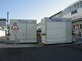
Peripheral facilities
The operational environment of the driverless transport system is shaped by the sum of the so-called peripheral devices . These facilities have a not insignificant influence on the availability of an AGV system, on the frequency of errors, possibly increased wear of the vehicles, etc. For example, a very important influencing factor is the nature of the soil, i.e. special requirements apply to an AGV-compatible floor Compressive strength, friction, evenness, expansion joints, inclines and slopes, electrical and magnetic properties.
Further components of the immediate operational environment of a vehicle are the course elements required for navigation and lane guidance:
- Guidelines or primary conductors in the ground (for guided vehicles or systems with contactless energy transmission)
- Guidelines on the ground (with optical or passive inductive guidance)
- punctiform floor markings (with grid navigation)
- Reflectors (for laser navigation)
The operational environment also includes the stationary load transfer stations and devices for power supply, but also elements along the route, such as B. fire doors, elevators and lifting platforms as well as shelves.
Driving course programming
An important part of the application modeling, which creates the database for programming the overall system, is the driving course programming , i.e. the modeling of the layout in which the vehicles move. It describes the routes with travel direction and speed information, blocking areas, load transfer stations, stops, battery charging stations, if necessary the position of reference marks, etc. It is usually done graphically, i.e. with the support of a CAD tool and based on a CAD layout the operational environment. With the help of an envelope curve simulation , the driving course layout can be checked for collision-free conditions. Since this type of driving course programming away from the vehicle, e.g. Takes place as the PC in the office, we speak of the so-called offline - programming .
The so-called teach-in is an alternative . Here, the vehicle is moved on the desired course with the aid of the manual control and the paths traveled are recorded / saved by the vehicle software. In the next step, the driving courses generated in this way usually have to be smoothed by software, since when driving by means of manual control e.g. B. no exact straight lines or arc segments arise. The teach-in procedure offers certain (time) advantages for small, less complex systems, but requires a lot of experience and practice. In particular - in contrast to offline programming - a vehicle is required that is not available for transport during this time.
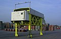
Example for an outdoor AGV system
- Container Terminal Altenwerder (CTA) of HHLA :
- Port of Gothenburg :
- Fully autonomous electrically powered semitrailer tractors without a driver's cab called "Vera" from Volvo Trucks , which transport semitrailers within the port area at speeds of up to 40 km / h for DFDS
Examples of automatic passenger transport systems
General
- People mover
- Personal Rapid Transit , cable car
Real plants
- H-Bahn in Dortmund
- H-Bahn and SkyTrain in Düsseldorf
- SkyLine in Frankfurt
- Underground in Nuremberg ( RUBIN )
- VAL in various cities
- Electromobile Ultra in London ( Citymobil )
Research projects
See also
literature
- Günter Ullrich, Thomas Albrecht: Driverless transport systems. A primer - with practical applications - on technology - for planning . Springer Vieweg, Wiesbaden 2019, 3rd edition, ISBN 978-3-658-27471-9 ( publisher information ).
- Container handling with battery AGVs · HHLA tests test vans for everyday practicality - goal: zero emissions without loss of performance . In: Daily port report of June 9, 2011, p. 4.
- HHLA sets Battery AGV on CTA one . In: Hansa , issue 7/2011, p. 8, Schifffahrts-Verlag Hansa, Hamburg 2011, ISSN 0017-7504
VDI guidelines
All of the above-mentioned VDI guidelines on the topic of driverless transport systems have been drawn up by members of the VDI technical committee "Driverless Transport Systems" (FA 309; previously: VDI department B7) and are published by Beuth-Verlag in Berlin. The overview page of the VDI on its website contains a list of the currently available VDI guidelines on the subject of AGVS / AGV .
Web links
Individual evidence
- ↑ VDI guideline 2510 "Driverless Transport Systems"; Beuth-Verlag, Berlin, p. 6 f.
- ↑ Directive 2006/42 / EC of the European Parliament and of the Council of May 17, 2006 on machinery and amending Directive 95/16 / EC (new version)
- ↑ Driverless transport vehicles will soon react automatically to faults. Retrieved November 13, 2017 .
- ↑ Hannover Messe 2016: Intelligent forklift understands language and gestures. Retrieved November 13, 2017 .
- ↑ Eckhard-Herbert Arndt: Electric drive belongs to the future in the port · Automatic transport platforms should be fed with green electricity from peak times . In: Daily port report of April 24, 2014, p. 2
- ↑ Lithium-ion AGV in the Altenwerder container terminal. Retrieved April 24, 2018 .
- ↑ http://www.conductix.de/de/produkte/inductive-power-transfer-iptr/inductive-power-transfer-iptr-floor?parent_id=6791
- ↑ https://vahle.de/produkte/vpower.html
- ↑ https://www.sew-eurodrive.de/produkte/energieuebertragung_energieversorgung/kontaktlose_energieuebertragung_movitrans/kontaktlose_energieuebertragung_movitrans.html
- ↑ DIN EN 1525 Safety of industrial trucks - Driverless industrial trucks and their systems , Beuth-Verlag, Berlin
- ↑ Guidelines for automated guided vehicles , wholesale and storage trade association, Mannheim
- ↑ Accident prevention regulation for industrial trucks , professional association regulation BGV D 27
- ↑ VDI guidelines for AGV security
- ↑ VDI guideline 4451, sheet 7 Compatibility of driverless transport systems, guidance control for AGVs ; Beuth-Verlag, Berlin, p. 3
- ↑ http://www.opentcs.org www.opentcs.org
- ↑ https://www.vdma.org/v2viewer/-/v2article/render/39830339
- ↑ https://www.vda.de/de/presse/Pressemommunikations/20190827-neue-schnittstelle-fuer-fahrerlose-transportsysteme.html
- ↑ https://www.vda.de/dam/vda/publications/2019/Logistik/VDA5050.pdf
- ↑ www.hafen-hamburg.de February 12, 2013: Transporting containers with excess green electricity ( memento of the original from May 19, 2013 in the Internet Archive ) Info: The archive link has been inserted automatically and has not yet been checked. Please check the original and archive link according to the instructions and then remove this notice.
- ↑ HHLA and DEMAG Cranes herald a new stage in electric mobility . In: Port of Hamburg Magazine 3/11, p. 10, Hafen Hamburg Marketing eV Hamburg 2011
- ↑ Vera - the future of autonomous transport , volvo.trucks.de, accessed on June 28, 2019
- ↑ DFDS tests autonomous transports · Electrically powered tractor unit in use at Gothenburg port terminal . In: Daily port report from June 19, 2019, p. 13