
turbocharger


A component for generating engine charging is referred to as a turbocharger , also known as exhaust gas turbocharger ( ATL ) or, colloquially , a turbo . It increases engine performance or the efficiency of combustion engines . It is therefore an auxiliary unit of the internal combustion engine. Its mode of operation consists in using part of the energy of the engine exhaust gas by means of a turbine within the exhaust system to drive a so-called compressor. This is to increase the fresh air pressure in the intake system and optimize the degree of filling of the cylinders and thus and thus more (for combustion necessary) more combustion air oxygen transport into the cylinder of the unit as a non-turbocharged naturally aspirated engine : its oxygen supply provides the suction motor rather only due to the negative pressure that its pistons generate in the cylinder during the downward movement, i.e. suck into it .
A turbocharger consists of at least one exhaust gas turbine , the energy (thermal energy, that is thermal energy , partly kinetic energy, that energy of motion ) of the ejected exhaust uses, as well as a generator driven by this turbine compressor for the intake air of the engine, which increases the air flow rate and the The piston suction work is reduced. Turbocharger the exhaust gases are usually designed for the benefit of pressure (congestion charging), some can additionally their kinetic energy use (pulse charging). Usually a charge air cooler is connected downstream of the compressor , which can achieve better filling at a lower temperature in the cylinder . The goal is usually to increase the cylinder charge.
The inventor of the turbocharger is the Swiss Alfred Büchi , who in 1905 applied for a patent for equal pressure or accumulation charging. In the 1930s were from the Saurer AG Adolph from Arbon Diesel - truck produced the first road vehicles with turbochargers.
How an exhaust gas turbocharger works
A large part of the losses occurs in thermodynamic cycle processes such as the diesel or Otto cycle through unused exhaust gas heat and the residual exhaust pressure (typically 3–5 bar), because the gas can no longer be expanded due to the limited compression ratio . With a naturally aspirated engine , it is discharged unused into the exhaust . It is more effective to recover part of this residual energy through further expansion in an exhaust gas turbine .
The shaft power of this high-speed exhaust gas turbine can be used in different ways:
- It can be coupled to the crankshaft of the engine ( turbo-compound engine ).
- It can drive an electrical generator that relieves or even makes superfluous an alternator that would otherwise be driven by the crankshaft .
- The power generated by the exhaust gas turbine can compress the charge air via a compressor. This has several effects:
- In the intake stroke, the piston is driven with overpressure instead of having to work against negative pressure as in the naturally aspirated engine .
- The degree of delivery increases, more air gets into the combustion chamber, which also increases the performance and the efficiency of the engine.
Recently, compressors driven by the crankshaft (colloquially also referred to as compressors ) such as rotary lobe compressors or Roots blowers have rarely been used, since the cheaply available power of an exhaust gas turbine can be used.
Charging in the four-stroke engine
In the four-stroke naturally aspirated engine , the pistons generate a negative pressure during the intake stroke , into which air or a fuel-air mixture flows under atmospheric pressure . At low speeds there is enough time so that the combustion chamber is almost completely filled with fresh charge . With increasing speed, however, the inlet valve opens ever shorter and with increasing flow velocity in the intake tract, increasing pressure losses impede the filling of the cylinder, the degree of delivery decreases and less and less fresh charge is available. By increasing the externally acting pressure with a turbocharger, significantly more fresh charge is pressed into the cylinder, especially at high speed, which increases the torque and, accordingly, the achievable engine output .

Charging with the two-stroke
In two-stroke engines , fresh charge is pressed into the cylinder in a short time while passing through the bottom dead center and the exhaust gases are expelled (dynamic charge exchange or " purging "), which in the case of the four-stroke engine takes two separate cycles. The rapid gas exchange in the two-stroke engine always requires at least one fan (in the simplest case, crankcase flushing ). With a turbocharger, an effectively increased boost pressure can only be built up if the exhaust closes before the intake, which is achieved with a controlled exhaust valve in the two-stroke diesel engine .
Structure & function
An exhaust gas turbocharger usually consists of an exhaust gas turbine and a turbo compressor on a common shaft. They are designed as radial flow machines, i.e. the gas flows from the outside to the inside of the turbine and from the inside to the outside of the compressor. The exhaust gas flow sets the turbine wheel in rotation. Its torque and speed are transmitted via the common shaft to the compressor wheel in the intake tract.

Turbocharger of a car (VW Golf)
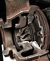
Exhaust side with turbine wheel and stator adjustment

Charge air side with compressor wheel

Storage of the turbo shaft

Storage of the turbo shaft


Turbo lag
As long as there is sufficient exhaust gas, the speed is sufficient to generate overpressure on the intake side. This state is only reached (with conventional motor vehicle engines) with a higher gas throughput from engine speeds of around 1500 to 2000 min −1 , so that turbo engines only work as naturally aspirated engines in the lower speed range. Even at higher engine speeds and at low loads, they have a delayed reaction to sudden acceleration, because the turbocharger first has to reach higher engine speeds in order to build up the boost pressure. This effect is called turbo lag .
performance increase
The increase in performance that can be measured on the crankshaft is based to a small extent on improved efficiency , but for the most part on the fact that more fuel can be burned in the larger air volume in the cylinder. This leads to higher engine mean pressure , higher torque and consequently more power. With gasoline turbo engines, the compression ratio often has to be reduced compared to a naturally aspirated engine , otherwise the fuel-air mixture may ignite uncontrollably ( knocking ) due to excessive total pressure and the resulting high temperature .
Charge air cooling
In contrast to the naturally aspirated engine, in which the intake air cools adiabatically in the intake stroke due to the negative pressure , the compression leads to a significant warming of the air to up to 150 ° C. Because warm air has a lower density, the filling and thus the performance of the engine can be increased even further by cooling the charge air after compression by a charge air cooler . Charge air cooling is used in practically all modern supercharged engines. Since the intercooler has a flow resistance and thus reduces the pressure generated by the compressor again, it should bring about a cooling of more than 50 K in order to achieve the desired increase in performance compared to an engine without charge air cooling.
In engines where the highest possible power output has priority over service life, the charge air can also be cooled by an additional water injection or injection of a water-alcohol mixture directly into the intake, which enables a further increase in performance.
Power regulation
Simple, unregulated turbochargers - like all turbo machines - have a narrow operating range with the best possible degree of efficiency, which is difficult to adapt to the engine map. A supercharger designed for the maximum output of the engine would build up too little pressure at medium output, and at low gas throughput there would even be an intake pressure loss because the slow compressor impeller stands in the way of the intake flow (see also turbo lag ). There are various techniques and design ways to mitigate this problem, particularly common bypass valve / wastegate , adjustable guide vanes (variable turbine geometry, VTG) and turbocharging . The techniques can also be used in combination.
Speed and bearing of the turbocharger shaft
The turbine and compressor work with impellers to convert flow energy into rotary motion and vice versa. Modern turbochargers can reach speeds of up to 290,000 revolutions per minute (for example smart three-cylinder turbo diesel). For such high speeds, the turbocharger shaft must be supported in a hydrodynamic slide bearing. In addition to the oil supply connections, some turbochargers also have connections for the cooling water circuit.
In some cases, one or two ceramic ball bearings are used in addition to the plain bearings. Ball-bearing turbochargers have less friction, which makes them respond faster. This accelerates the speed increase of the supercharger and lets the boost pressure start earlier.
Jam charging and burst charging
During back-up charging, the exhaust gases are brought together, collected and only then directed to the exhaust gas turbine. The turbine is primarily designed to use the pressure difference between the exhaust manifold and the exhaust pipe. The flow towards it is almost even. In the pulse charging the turbine is primarily designed to evaluate the kinetic energy use of the ejected gases for charging. For this purpose, it is connected to the outlets of the cylinders via narrow and as short pipes as possible. In multi-cylinder machines with impulse charging, the exhaust gases are fed through several pipes and enter the turbine through a group of nozzles. The exhaust pipes must be brought together in such a way that the cylinders connected to the respective pipe do not emit exhaust gases at the same time. With shock charging, the pressure at the outlet valve drops below the purge pressure after an initial sharp rise due to the inertia of the expelled gas mass, which favors the gas exchange. The accelerated gas mass hits the turbine and drives it. The exhaust gas pressure at the turbine fluctuates much more strongly than with accumulation charging.
Alfred Büchi also developed the turbocharger with shock charging.
Advantages and disadvantages of turbocharging
advantages
Exhaust gas turbocharging enables the maximum mean effective pressure and thus the torque and maximum power to be increased for a given displacement. This increase either results in a more powerful engine with approximately the same dimensions and weight as the original, uncharged engine, or enables the same performance to be achieved from a smaller machine ( downsizing ). The performance potential of turbocharging became clear in Formula 1 engines in the 1980s , when the most powerful turbo engines with a displacement of 1.5 liters achieved outputs of more than 750 kW in training.
The overpressure of the charged supply air pushes the piston downwards and ensures that no energy has to be used for suction.
A major advantage of the exhaust gas turbocharger over the compressor is that the exhaust gas turbocharger uses at least some of the otherwise unused overpressure (approx. 3 bar at maximum output) of the exhaust gases, i.e. it requires little additional output for its operation. With the turbocharger, the hot exhaust gas flows out of the cylinder at high speed and sets the turbine in rotation (the piston then pushes out the rest of the exhaust gas, although the exhaust gas back pressure is higher than with a non-supercharged engine or one with a compressor - see also under "Disadvantages" below). On the other hand, a compressor is mechanically coupled directly to the engine (toothed belt, gear wheels, chain, V-belt) and thus directly draws useful power from the engine. One advantage of the compressor is that it generates overpressure even at a lower speed than a turbocharger. The overall efficiency of the "Turbo" system is higher than that of the "Compressor" system.
disadvantage
Charging leads to higher mechanical and thermal loads as well as higher mean pressures. This is why some components have to be reinforced, for example the engine block , cylinder , cylinder head , valves , cylinder head gasket , pistons , piston rings , possibly connecting rods , crankshaft and some bearings . This generally increases the vehicle weight.
If the turbocharger is provided as part of a downsizing, the torque and power remain roughly the same and the previous drive train can largely be retained.
Some components of the turbocharger may need to be cooled (for example with an oil cooler) (especially its bearings).
Since the charger draws its energy from the pressure gradient between the exhaust gases and the ambient air, the cross-section of the exhaust system must be large enough so that there is no excessive counter pressure in the exhaust. The back pressure should not be above about 5 kPa (the standard atmospheric pressure is about 100 kPa).
In the case of supercharged gasoline engines, the exhaust gas turbines of which can get red-hot, some manufacturers recommend not to switch off the engine immediately after driving under high load, but rather to let it run for a few tens of seconds at idle so that the charger can continue to rotate as it cools down. If this does not happen, the oil-lubricated plain bearings of the shaft can be irreparably damaged by overheating.
So-called turbo timers are one way of preventing this . These allow the engine to continue running for an adjustable time after the ignition has been switched off. However, some insurance companies will no longer accept the vehicle because the engine will continue to run when the ignition key is removed. Such follow-up regulators usually do not have a general operating permit within the scope of the German StVZO . Another option is to use an electric pump. This can also work when the engine is switched off and cool the loader.
In motor vehicles in particular, a control system relating to the turbocharger is necessary, which is intended to reduce the susceptibility to failure, but can also suffer disruptions itself. Diagnosing certain types of damage can be more complicated on turbocharged engines than on similar engines without. Modern fully electronic vehicle diagnostic systems (" OBD ") facilitate diagnosis.
The principle and structure section describes that the bearing is included in the engine oil circuit. The plain bearings of the turbochargers are supplied by an engine-driven oil pump. During the acceleration process (transient operating behavior) the turbocharger does not generate sufficient boost pressure, so that a brief negative pressure arises in the intake system, which can suck in oil from the turbocharger bearing and feed it to the combustion chambers. Depending on the driving interval, it is estimated that 30 to 40% of engine oil consumption comes from the storage of the turbocharger. This engine oil produces soot particles, some of which - if not burned - are discharged without filtering.
When accelerating from low engine speeds, older turbo engines in particular lacked the correct amount of exhaust gas to generate the desired boost pressure. Charging only started when a sufficiently strong exhaust gas flow was available with increasing engine speed. In general, the power output begins with a delay when suddenly accelerating, since the exhaust gas flow must first accelerate the turbine sufficiently for the boost pressure to be established. This delay in the event of sudden changes in load is known as turbo lag . These peculiarities could be largely compensated for by control systems and the use of smaller turbochargers or specially shaped channels in the cylinder head. Due to the design: a small charger responds faster than a large one due to the lower moving mass; however, a large supercharger can achieve a higher maximum output from the same displacement.
In rally vehicles there are anti-lag systems which counteract the drop in the turbo charger speed and thereby prevent or mitigate turbo lag .
Boost pressure regulation
The shaft of the exhaust gas turbocharger rotates faster and faster as the engine speed and power increase due to the increasing amount of exhaust gas that drives it. The faster the turbine rotates, the more air the compressor delivers, which in turn accelerates the turbine further due to the increasing amount of exhaust gas. At a certain speed, the compressor reaches its delivery limit, and the mechanical and thermal limits of the turbocharger or the motor are threatened to be exceeded (e.g. the friction in the bearings). The desired supercharging of the engine at low speeds can therefore become problematic in higher ranges. Therefore, turbochargers without boost pressure control must be designed in such a way that they are working at their performance limit at full load, which creates a very large turbo lag. In order to avoid this, exhaust gas turbochargers are nowadays provided with a boost pressure control which enables the charger to have a high output even with low exhaust gas flows and nevertheless not exceed the load limit at high speeds; the compressor speed reaches a speed plateau. This regulation can be implemented in different ways. The regulation has become established via a wastegate (mainly for gasoline engines) or via adjustable guide vanes (VTG, mainly for diesel engines). In modern systems, the engine control unit calculates a target boost pressure. A pressure sensor, which is usually positioned in front of the throttle valve, supplies the current actual boost pressure to the engine control unit. The task of boost pressure control is to compensate for the difference between the target and actual boost pressure as quickly as possible. To do this, the boost pressure control moves the existing actuator (wastegate or VTG) as a control value.
Both actuators are controlled either pneumatically-mechanically or electrically. In the pneumatic solution, there is a sender on the compressor side: from a certain boost pressure, it increasingly adjusts the wastegate or the guide vanes, which counteracts a further increase in the boost pressure. In the case of newer motors, electrical actuators are increasingly being used, which can set intermediate positions in addition to "open" or "closed". One advantage of the electrical control is that the valve can be set in the entire map area independently of the boost pressure. This allows the actuator to respond to different requirements (such as overrun fuel cutoff). In addition, the boost pressure can be increased for a short time to enable an "over boost". In addition, electrical controls have a higher actuating speed and higher locking forces in order to reduce leakage in a wastegate valve.
Wastegate

A variant of the boost pressure control is the bypass valve (also called wastegate ) in the exhaust gas flow. This valve can bypass part of the exhaust gas flow past the turbine in order to avoid an increase in the boost pressure. This means that a charger can be used that produces enough boost pressure even at low engine speeds and thus reduces the turbo lag. At higher supercharger speeds, part of the exhaust gas mass flow bypasses the turbine so as not to overload the supercharger. It is common for the bypass valve to be integrated directly into the turbine housing as a flap (see picture on the right). However, this method of boost pressure regulation has the disadvantage that when the wastegate is open, only part of the energy is no longer used, but only part of the exhaust gas. Due to their position in the hot exhaust gas flow (approx. 1000 ° C), the bypass valve and its actuators are subject to high thermal loads and are therefore prone to failure. That was one of the reasons why individual engine manufacturers turned away from the turbo-charging of gasoline engines and used compressor systems that work without components in the exhaust gas flow.
The wastegate is usually controlled by a vacuum unit, an overpressure unit is less common. Since the system-related high temperatures at the turbocharger lead to a high thermal load on the plasticizer-containing vacuum lines and ultimately to their material fatigue (cracks), more and more newer turbochargers have an electronically controlled wastegate. This reduces the susceptibility to errors and the wastegate can be set more quickly. In addition, complex line systems for generating the negative pressure can be omitted.
Adjustable guide vanes (variable turbine geometry, VTG)

Turbines with adjustable guide vanes work in a similar way to a Francis turbine . The guide vanes in the exhaust gas flow in front of the turbine wheel are adjustable, which means that the gas can be given a higher angular momentum (in the form of a higher tangential velocity) at low throughput . They are arranged in the turbine housing directly in front of the turbine inlet. The angle of incidence of the guide vanes is regulated in such a way that when there is little gas throughput, the exhaust gas is accelerated tangentially through reduced flow cross-sections and directed onto the turbine blades, which increases the speed of the turbine and thus the performance of the compressor. Conversely, with a high gas throughput, the flow velocity can be reduced by using large cross sections.
In 1989, Honda used its experience with turbo engines from Formula 1 and launched a variant of the Honda Legend called Wing turbo with a VTG turbo. The regulation was controlled by a digital computer. The 2-liter engine developed 142 kW (193 hp) at 6000 rpm.
Turbochargers with VTG have also been used in diesel engines for passenger cars since 1996. The TDI diesel engine with direct injection from VW / Audi with a maximum output of 81 kW (110 PS) was the first car drive to achieve an engine efficiency of over 40% thanks to its variable turbine geometry. The adjustable guide vanes have now established themselves as the standard for diesel engines.
Porsche used its first gasoline engine with VTG in the 911 Turbo (997) (sales started in Germany in June 2006). In order to be able to withstand the exhaust gas temperatures of up to 1000 ° C compared to diesel engines, high-temperature alloys (tungsten steels) must be used. The modern VTG turbocharger for gasoline engines was developed in close cooperation with BorgWarner Turbo Systems . In the "1.5 TSI BlueMotion", VW is using a VTG charger for a large-scale production gasoline engine for the first time. Since the engine has relatively low exhaust gas temperatures (~ 860 ° C) due to the intake valves closing early, it can be used. The charger was developed by Honeywell. Another well-known term for turbochargers with adjustable guide vanes is also VNT (Variable Nozzle Turbine). This designation is used by Honeywell for their turbo systems with variable turbine geometry under the brand name Garrett .
Recirculation valve
Mode of operation without recirculation valve
When the throttle valve is closed in gasoline engines, the moving air column hits the valve. The air column (pressure column) reverses, runs in front of the rotating compressor wheel of the turbocharger and brakes it heavily, which can lead to the destruction of the turbocharger in the long term if the boost pressure is high (or if the air circulation valve is defective). In addition, strong flow noises can be heard because the flow stops at the compressor (“pumping”).
Function with air circulation valve
To prevent this ineffective braking, the air is let out through the air circulation valve. In this way, the charger can continue to rotate freely, a renewed pressure build-up is shortened and a faster acceleration of the turbocharger is achieved in favor of a better response behavior after the gear change.
Universal (mostly intended as open systems) chargers from the aftermarket can almost always be set in a defined range to respond to a specific pressure threshold. This is less common with factory-installed loaders, in order to prevent improper changes to the factory settings.
Recirculation valves are nowadays installed in almost all turbo - charged gasoline engines and are also used in American Indy 500 racing vehicles.
Open / closed systems
With the open system, the excess air is not returned to the intake duct (closed air recirculation valve / system), but discharged to the outside. Systems with a valve are common. In some cases, systems with two integrated valves are also used, which enable a more sensitive overpressure release. Attaching to an engine with an air mass meter can be problematic because the air that gets into the open air instead of into the intake tract has already been recorded by the engine control unit and the amount of fuel is adjusted accordingly to form the correct mixture. As a result of the lack of air, the mixture becomes over-rich, the engine performance drops, the engine can stutter, the lambda probe and the catalytic converter can be destroyed by gasoline entering the exhaust and igniting. We therefore strongly advise against converting to an open system (without reprogramming the engine control unit). In addition, the vehicle no longer complies with the general operating permit (ABE), since unfiltered oily exhaust gases (through the oil lubrication of the turbocharger and the crankcase ventilation that leads into the intake system) are released into the environment.
Valve types
Two types of valve are common for the air circulation valve, diaphragm or piston. The piston responds more sensitively and closes faster, but there is a risk of the piston jamming and thus a malfunction (remains open or does not open).
Since an electric actuator is significantly faster than a conventional pneumatic actuator, an electrically controlled valve is used in some motors. The electrical valve is opened or closed via a control device or a simple electrical circuit and can thus be controlled as required regardless of the pressure. It can also be used in a diesel engine, but there is no technical sense there, as there is no throttle valve, and only serves as a show effect through the loud blow-off noise in an open system, depending on the boost pressure.
The characteristic noise of diaphragm valves is a bright whistling hiss, whereas piston valves only hiss loudly at high boost pressure and tend to "flutter" at low boost pressure. However, the discharge noises also vary greatly depending on the design and manufacturer of these valves.
From a technical point of view, it is not entirely correct that the electronically controlled valves (technically superfluous valves in diesel engines) are also referred to as blow-off or pop-off valves, since the blow-off valves are always pressure-controlled in the actual sense.
Common names
English-language terms for blow-off valve, drain valve or (thrust) air circulation valve, which are also often used: Blow-Off-Valve (BOV), Pop-Off-Valve (POV) (German: "Pop-Off-Ventil")
Other types
Biturbo / Twin Turbo

Biturbo or “Twin Turbo” is the term used to describe the parallel use of two chargers. Bi is the Latin prefix for two , twin means "twin" (English). This type of construction uses two smaller loaders instead of a single large one. For example, in a four-cylinder twin-turbo engine, each turbocharger is driven by the exhaust gases from two cylinders. By using two smaller turbochargers with correspondingly lower moments of inertia, the response behavior when accelerating and the efficiency of the entire system can be improved. To a small extent, engines with more than two turbochargers have also been developed in order to achieve further improvement. The Bugatti models EB110 , Veyron and Chiron have four turbochargers.
Sequential biturbo
With a sequential biturbo, both turbines are not constantly driven by the exhaust gases, but the second turbine is only switched on when the corresponding power requirement is reached and then drives the second compressor. Once this has happened, the chargers work in parallel according to the biturbo principle. In general, the exhaust gases from all cylinders are available to both turbochargers; they are not each assigned to a cylinder bank, so that the first turbocharger can be operated by the exhaust gases from all cylinders at low speeds. The aim of this technology is to improve the usability of the speed range. In the upper speed range one has the advantage of the larger delivery rate of two turbochargers, while in the lower speed ranges the low inertia of only one turbine causes a quick and early build-up of the boost pressure and thus a good response behavior. Examples:
- Petrol engine: The 3.0-liter in-line six-cylinder twin turbo, which was used in the Toyota Supra (JZA80) from 1993 (the Supra is referred to as a twin turbo, not a biturbo).
- Diesel engine: The 2.2-liter four-cylinder biturbo diesel engine from Ford / PSA (DW12BTED4); the 2.0 CDTI BiTurbo (143 kW / 195 PS, 400 Nm torque) from Opel ( available in the Opel Insignia since January 2012 )
Register charging

Register charging (also known as sequential charging) is the parallel, alternating use of turbochargers. A smaller charger is used for low engine speeds, which revs up faster even with a low exhaust gas flow and due to the low mass inertia. If there is a larger amount of exhaust gas, a switch is made to a large turbocharger, which then provides sufficient air mass and pressure for the high fresh air requirements of higher engine speeds. The different turbochargers can be better matched to their area of activity and the small charger reduces the so-called "turbo lag": At low engine speeds, the mostly large charger was not able to achieve a sufficiently high turbo speed to build up overpressure in the intake area . Below this critical level, a normal turbo engine works more as a naturally aspirated engine, possibly even throttled by the “braking” turbine blades. Register supercharging is only found in a few powerful engines in automotive engineering to this day. The first (small) series vehicle with a register turbo was the Porsche 959 .
There are also charging concepts with a combination of register charging and multi-stage charging, for example with the engines of the BMW models 535d (E60 / 61 series) , 335d , 123d , and with some versions the Mercedes-Benz diesel engines OM646 , OM651 and the 180 hp -Model of the Saab 9-3 diesel engine. The compressors of the smaller and larger turbochargers work in series on the intake side. If the power requirement is low, the air is only compressed by the compressor of the smaller charger. When the load is higher, the larger supercharger is activated by controlling the exhaust gas flow and regulating the bridging of the first compressor. A characteristic map control of the gas control on the exhaust gas as well as on the fresh gas side in interaction with the fuel injection can largely suppress torque fluctuations in the transition area.
Multi-stage charging
With multi-stage charging, the air is compressed by several compressors connected in series. The compression ratios that can be achieved in this way can only be used sensibly under conditions of greatly reduced external pressure, so that this technology only played a role in the development of aircraft engines. In the case of multi-stage turbocharging, mechanical superchargers and turbochargers were initially combined. The test engine Daimler-Benz DB624 (test bench trials from 1944) contained a combination of two mechanical gear chargers and an exhaust gas turbocharger. The designed full pressure height was 15,000 to 17,000 meters.
The combination of a piston engine and (multi-stage) turbo engine is called a “compound” drive. Napier tested compound engines in the late 1940s, but these engines with diesel engines, called Napier Nomad, never got beyond the experimental stage.
A multi-stage turbocharger was provided for the drive of the high-altitude research aircraft Grob Strato 2C, which was developed from 1989 onwards , with the first and second stages consisting of the low and medium pressure compressors of a three-shaft turbo-prop engine ( Pratt & Whitney Canada PW127 ). All components were housed in the engine nacelle. After passing through the turbine of the turbocharger, the exhaust gas was directed into the turbine section of the original turboprop compressor. The air compressed by the compressor stages was fed to the compressor of the turbocharger and then to the engine. The maximum pressure ratio was 1:45, which made large charge air coolers necessary. The designed full pressure altitude was 24,000 meters, the maximum flight altitude 26,000 meters. However, the project was not pursued for financial and political reasons.
Twin scroll loader

Twin-scroll chargers differ from other chargers in that the design of the turbine housing is different and they are an alternative to bi-turbo concepts with two exhaust gas turbochargers arranged in parallel. The spiral casing of the twin scroll turbine is divided into two parallel flow channels by a flow divider. In conjunction with a double-flow exhaust manifold, this enables the exhaust gases to be fed separately to the turbine wheel. The aim here is to prevent, as far as possible, a mutual unfavorable influence of the individual cylinders during the gas exchange. In the exhaust manifold, the exhaust ducts of two cylinders (in the case of four-cylinder engines) or three cylinders (in the case of six-cylinder engines) are combined into one line and, due to the structure of the twin-scroll turbine housing, are only brought together again directly in front of the turbine wheel. The selection of the cylinders is based on the ignition sequence of the engine, so that successive cylinders are always assigned to different exhaust lines. The positive effects of the twin-scroll charger are reduced exhaust gas back pressure and improved gas exchange in the engine, which in turn improves fuel consumption, performance and responsiveness. This type of turbocharging is used, for example, by Fiat Chrysler Automobiles in the Alfa Romeo Giulia 2.0 Turbo MultiAir or Opel in the Astra J OPC . The twin scroll charger must not be confused with a scroll compressor ("G-Lader"), which is a piston engine .
Turbo compound
In the turbo compound technique conventionally operating a turbocharger or a compressor having a downstream exhaust gas turbine which is mechanically connected to the crankshaft is combined.
This second turbine uses the energy of the exhaust gas, which is still hot after exiting the first charger. The result is a higher torque with increased energy utilization, i.e. a further improvement in efficiency .
Instead of coupling the turbine to the crankshaft, it can also drive an additional generator to support the electrical system. This is possible both in connection with the turbine of the exhaust gas turbocharger and with a separate downstream turbine.
Intercooler
Since the pre-compression increases the air temperature and thus counteracts the desired increase in the amount of intake air, charge air coolers were developed to compensate for this disadvantage. Charge air coolers always increase the thermodynamic efficiency of the engine.
Turbo charging in motor vehicles
Use in diesel engines
In diesel engines for passenger cars as well as for trucks, the exhaust gas turbocharger has meanwhile become the " state of the art ", since a liter output that approximates that of a ( gasoline ) gasoline engine can only be achieved by turbocharging . Without turbocharging, a comparably powerful engine would have to have almost twice the displacement and therefore be significantly heavier. In addition, the specific torque characteristics of a turbo diesel compared to a naturally aspirated diesel shift the range of maximum power development to lower speed ranges. As a result, such engines offer a high degree of "elasticity", so that you have to shift into lower gears less often to accelerate.

In principle, diesel engines do not need a throttle valve. Therefore, a gas flow is present at the turbocharger even during overrun. This means that the speed of the turbine does not drop as far as in a gasoline engine, which improves the response behavior when there are load changes. Diesel technology is therefore very well suited for the effective use of a turbocharger. The high compression of diesel engines (which is one reason for the high degree of efficiency) results in a lower exhaust gas temperature, so the material of the diesel turbocharger is exposed to less high loads.
Large diesel engines were equipped with turbochargers or external compressors at an early stage (the two Hanseatic cities of Gdansk and Prussia , which were commissioned in 1926, were the first ships with charged diesel engines ). The first diesel locomotives at the end of the 1930s also had exhaust gas turbochargers. Turbochargers only appeared in motor vehicles much later because the - much smaller - turbochargers suffered greater losses. Furthermore, for a long time it was not possible to achieve a favorable torque curve and prevent incomplete combustion when the engine was accelerated. These problems were solved at the beginning of the 1950s with favorable characteristics for low-pressure charging. In 1951 MAN equipped an engine for trucks with a self-developed turbocharger, with the 8.72-liter engine being increased in output from 130 to 175 hp. The truck manufacturer Volvo built a turbocharger onto its engines from 1954, which brought about the breakthrough in truck engine construction due to its reliability. Turbochargers have been used in a very high proportion of the large commercial vehicles delivered since the 1960s. The Mercedes 300 SD was the first car with a turbo diesel engine to hit the market in May 1978 . Since 1988, passenger cars with diesel turbocharged engines with charge air coolers and direct injection have gained great importance in Europe.
Use in gasoline engines

In gasoline engines with external mixture formation , the boost pressure is limited by the heat of compression produced by the fuel-air mixture in the second cycle. Exceeding this means uncontrolled self-ignition and thus engine knocking or engine ringing . The start of knocking can be shifted upwards using high-octane fuel, an effective charge air cooler or water-methanol injection . In most cases, however, the valve timing is changed and the compression reduced to prevent this effect.
Because of the higher exhaust gas temperatures compared to diesel, the use of turbochargers in gasoline engines is more difficult and requires highly heat-resistant materials. Nevertheless, the advantages also outweigh the advantages of gasoline engines, which is why the majority of modern gasoline engines rely on turbocharger charging.
Use in cars and motorcycles
The first supercharged engines were installed in the ALFA-24-HP models from 1910 , which were adopted from the aircraft developed by the same manufacturer (see below). Mass-produced cars with supercharged gasoline engines first came in the USA from 1961 as the Oldsmobile F-85 Jetfire (aluminum V8 with 215 cui ≈ 3.5 liters displacement, 160 kW, 218 SAE hp and methanol-water injection , until 1963 Program) and from 1962 as the Chevrolet Corvair Spyder (six-cylinder boxer turbo, displacement: 145 cui; ≈ 2.4 liters, 110 kW, 150 SAE hp).
In Europe, the Swiss engineer and entrepreneur Michael May initially equipped the Ford 20M and later also other car models with turbochargers from 1966 . In Germany, turbocharged cars went into series production in 1973 with the BMW 2002 turbo and in 1975 with the Porsche 911 turbo . However, both had little success due to the oil crisis. In 1978 the Saab 99 Turbo came onto the market, in which a fast-responding, small turbocharger was combined with a control valve (wastegate). The maximum output was only slightly increased, but the engine delivered a high torque at low revs. The Saab 99 Turbo was the first turbocharged production car that was not produced in small numbers as sports equipment, but in large series.
Gasoline engines are only supercharged to a small extent, even if there has been a significant increase in recent times, preferably in high-performance models. The trend is towards so-called downsizing concepts, in which smaller, supercharged engines replace larger, non-supercharged engines. The aim of downsizing is lower consumption by dethrottling the engine. Further advantages result from reduced weight and reduced friction.
Turbocharged engines - both gasoline and diesel engines - are usually more expensive to manufacture than comparable naturally aspirated engines, and they are also complex in terms of control technology (control of the pressure-reducing valves such as the wastegate or the air circulation valve). When accelerating after overrun phases, mainly in the lower speed range, turbo engines develop their power somewhat delayed. This so-called turbo lag is usually more pronounced in gasoline engines than in diesel engines. Advances in design (adjustable guide vanes, smaller and therefore faster responsive loaders, lighter paddle wheels with lower mass inertia) and in control technology made it possible to reduce it significantly.
In the past, turbo engines were said to have a higher consumption, which is usually put into perspective to the higher absolute consumption of the more powerful supercharged engine. Modern turbo gasoline engines specifically consume less fuel than naturally aspirated engines with the same output (measured in grams / kilowatt-hour, previously in grams / hp-hour). In Formula 1 , too, the turbo engine (previously prohibited there according to the regulations, but reintroduced from the 2014 season) was superior to the naturally aspirated engine in terms of specific consumption. However, an absolutely higher power also causes a higher absolute fuel consumption.
Almost all large-scale manufacturers now offer turbo-charged gasoline engines; Diesel engines without supercharging play practically no role on the European market.
As early as 1985, Lancia developed a racing engine with an exhaust gas turbocharger and supercharger in motorsport (for "Group B") and used this engine in the 200 series models of the Lancia Delta S4, which are prescribed by homologation rules . In 1988, Nissan also installed such an engine in a small-scale motorsport series of the Micra model , which, however, achieved 81 kW (110 hp) and a specific torque of 144 Nm / l at 4800 rpm from a displacement of just 0.9 liters. The VW TSI large series engine (Golf GT, 1.4 L with 125 kW / 170 PS, from 2005) combines direct injection with a turbocharger for high speeds and a Roots compressor for low ones; the engine reaches a specific torque of 200 Nm / l at 1500 rpm.
At the beginning of the 1980s, series motorcycles ( Honda CX 500 Turbo , Yamaha XJ 650 Turbo , Kawasaki Z750 Turbo) were also offered with turbochargers without great market success. In addition, the sudden increase in performance when reaching a certain engine speed made these motorcycles more difficult to control, especially when accelerating (also because of their significantly lower weight compared to a car).
Turbo charging in aviation

During the First World War, attempts were made to mechanically couple exhaust gas turbines with charge fans and thus create an exhaust gas turbocharger. Before and during the Second World War, the development was pushed further, but engine technology was dominated by mechanical supercharging until the end of the war. In Germany there were additional turbochargers (multi-stage charging) only for special high-altitude applications, initially in the various versions of the Junkers opposed piston two-stroke diesel aircraft engine Jumo 207 , and in significant numbers in the BMW 801 TJ-0.
In the USA, the Lockheed P-38 received the Allison V-1710 with General Electric turbocharger.
After the war, until the introduction of the turboprop and turbine jet engines for line engines, some very highly developed engines with exhaust gas turbines (non-turbochargers) such as the Wright R-3350 were built for a few years . The crankshaft drove the centrifugal compressor via a two-speed gearbox. The three exhaust gas turbines were connected to the crankshaft via fluid couplings and gears. They delivered 550 hp (410 kW) additional power.
Today engines with exhaust gas turbochargers, mainly gasoline engines, are mainly used in medium-sized private and business aircraft. A distinction must be made between two different methods of turbocharging:
Turbo supercharging
The pressure in the intake tract (upper deck, boost pressure) can be increased by adjusting the throttle valve to in some cases far above the full pressure level. This means that more power can be drawn from the engine than the nominal power (starting power). In most cases this is limited to a maximum of five minutes. Motors of this type have a lower compression than the suction versions. Examples: TSIO-520-UB (Continental, Beech Bonanza B36TC), TIO-540-AE2A (Lycoming, Piper Malibu Mirage). The disadvantages of this version are the increased signs of wear and tear due to additional loads and higher operating temperatures.
Turbo normalizing
The pressure in the intake tract (upper deck, boost pressure) specified by the throttle valve adjustment is kept constant via a hydraulic regulator and a blow-off valve (waste gate). The maximum possible boost pressure corresponds to that at full pressure height. The engine is constructed like the naturally aspirated version, except for the supercharger, but can deliver its maximum rated power to very high altitudes (> 20,000 ft) because of the constant boost pressure.
Intercooler
The intercooler was not considered to be important in aircraft engines for a very long time, as it was assumed that it would be used in a car engine (generating more power through higher air density). As a result, the service life of turbo-charged aircraft engines did not correspond to the manufacturer's specifications for a long time due to the additional temperature load caused by the heated charge air, which was associated with increased (repair) costs. Modern supercharger systems have highly efficient intercoolers, which enable the operator to keep the engine temperature (especially that of the cylinder heads) within tolerable for the service life of the engine and the maintenance costs in all working points and even in extreme weather conditions (high summer, desert operation, etc.) To keep boundaries.
Charging makes it possible to fly at higher altitudes, which has economic advantages because of the lower air resistance there. The external pressure of the air, which decreases with increasing altitude, also improves the efficiency of the exhaust gas turbine, which justifies the cost of charging for power classes between naturally aspirated and turboprop. An example of a supercharged engine is Bombardier's Rotax 914. The preparation for production of the Bombardier V300T has been discontinued since 2006 and certification is no longer carried out.
In recent years, turbo engines have also been developed for smaller aircraft (for example the Thielert diesel ), the advantages of which are low consumption and ease of use.
Turbocharger manufacturer
- ABB Turbo Systems
- BorgWarner Turbo Systems (Schwitzer & 3KWarner, formerly the turbocharger division of KKK )
- Bosch Mahle Turbo Systems
- Caterpillar
- Continental AG
- Cummins Turbo Technologies (Holset)
- Hitachi Warner Turbo Systems (joint venture between Hitachi and BorgWarner )
- Honeywell Turbo Technologies ( Garrett )
- HKS turbos
- IHI Charging Systems International
- Komatsu
- Compressor construction Bannewitz (KBB)
- MAN Diesel & Turbo
- Mitsubishi Heavy Industries
- MTU Friedrichshafen
- NAPIER Turbochargers
- Pierburg
- Voith Turbo
- Garrett AiResearch
literature
- Michael Mayer: exhaust gas turbocharger. Sensible use of exhaust gas energy . 5th edition. Verlag Moderne Industrie, 2003, ISBN 3-478-93263-7 .
- Gert Hack , Iris Langkabel: Turbo and compressor motors . Development, technology, types . 3. Edition. Motorbuch Verlag, Stuttgart 2001, ISBN 3-613-01950-7 .
- Heinz Grohe: Otto and diesel engines . 11th edition. Vogel Buchverlag, 1995, ISBN 3-8023-1559-6 .
Web links
Individual evidence
- ↑ Patent DE204630 : Internal combustion engine system. Published on November 28, 1908 , inventor: Alfred Büchi.
- ↑ www.saureroldtimer.ch ( Memento from July 28, 2010 in the Internet Archive )
- ↑ a b c Gert Hack: Making Cars Faster - Automobile Tuning in Theory and Practice. Motorbuch-Verlag, 16th edition. 1987, ISBN 3-87943-374-7 , pp. 83/84.
- ↑ Heinz Grohe: Otto and diesel engines. 11th edition. Vogel-Verlag, Würzburg 1995, ISBN 3-8023-1559-6 .
- ↑ http://dwolsten.tripod.com/articles/jan89a.html/ English
- ↑ http://media.opel.com/ (English, December 5, 2011)
- ↑ atzonline.de ( page no longer available , search in web archives ) Info: The link was automatically marked as defective. Please check the link according to the instructions and then remove this notice.
- ↑ Kyrill von Gersdorff, Kurt Grasmann, Helmut Schubert: Aircraft engines and jet engines . 3. Edition. Bernard & Graefe, 1995, ISBN 3-7637-6107-1 .
- ↑ charging of diesel engines. In: Automotive Technology . 11/1958, pp. 408-414.
- ↑ Heiner Buchinger: Rover V8 Story, in Roverblatt, p. 16ff.
- ↑ Capri I 2300 GT with May turbocharger - The gentle force with May turbocharging , 2 , 3 , 4 , 5
- ↑ Innovation + technology in the 90 kW TSI VW engine ( Memento of the original from January 30, 2010 in the Internet Archive ) Info: The archive link was automatically inserted and not yet checked. Please check the original and archive link according to the instructions and then remove this notice.
- ↑ http://www.conniesurvivors.com/1-twa_flightengineer.htm website about the Lockheed Super Constellation
- ↑ BRP-Rotax shelves its V6 aircraft engines project ( Memento from November 6, 2010 in the Internet Archive )