
Forming
The forming (also plastic forming ) is in accordance with DIN 8580 one of the six main groups of manufacturing processes . The main manufacturing processes of forming are the rollers , the forging , the forging , the extrusion , the extrusion , the deep drawing and bending . It is therefore to processes in which blanks of plastic materials ( metals and thermoplastic plastics are brought) selectively in a different form, without material from the blanks to remove as in the separating added to admit or as in the joining . The material retains its mass and its cohesion. When separating and joining, on the other hand, the mass and cohesion are reduced or increased.
Forming differs from deforming in that the change in shape specifically introduced. Deformation, on the other hand, is an untargeted plastic change in shape (e.g. in a road traffic accident ).
The individual procedures are grouped according to various criteria:
- Depending on the dimensions of the workpieces, a distinction is made between massive forming , sheet metal forming and wire forming .
- Depending on the temperature, a distinction is made between cold forming , in which the strength of the workpieces increases during processing, and hot forming .
- In DIN 8580, the processes are divided according to the mechanical stresses that act in the workpieces, in compression forming, tensile compression forming, bending forming, etc.
After the primary forming , most of the materials are further processed by forming into semi-finished products ( sheets , wires and other profiles (e.g. rods, billets )). For the production of mass products , further forming of the semi-finished products is usually the most economical process. The advantage is, among other things, the good use of material. In addition, forming processes enable a load-oriented fiber flow compared to chip-removing processes or casting processes.
Important forming machines are bending machines , presses , drop hammers , Oberdruck- and counterblow hammer , screw presses , eccentric presses and hydraulic presses . Most are suitable for several manufacturing processes, depending on the tools installed.
The change in shape is usually a degree of deformation indicated together with the yield stress , which is the voltage which is necessary to cause a plastic deformation in the flow curves recorded. The forming force and the forming work can be calculated from this.
Definition, classification, demarcation from deformation
Forming is one of the six main groups of manufacturing processes and is therefore at the top of the system. The neighboring five main groups are the U r shape , cutting , joining , coating and change material properties .
Reshaping is defined in DIN 8580 as "manufacturing by plastic or plastic changing the shape of a solid body."
The common classification criterion is the cohesion of the material. It is retained during reshaping, i.e. neither reduced as it is when separating or increased as it is when joining. It follows that no components are added to or removed from the raw part. The mass also remains unchanged. In practice, most of the materials used in forming technology are approximately incompressible. The volume of the blank is therefore also approximately retained. This law of constant volume is an important calculation basis in forming technology.
When deforming , the change in shape is caused randomly or unintentionally. For example in a traffic accident . When To contrast form is the strain targeted and deliberate. Similar to the terms rebuilding and remelting.
Plasticity as a prerequisite
Metals and their alloys have the ability to permanently change their geometrical shape under the influence of external forces, without the material context being lost or the workpiece mass changing. This effect, known as plasticity , is due to the structure of the metals.
Metals are made up of crystallites whose orientation is isotropic or anisotropic . Plastic changes in shape of metallic materials occur through flowing on crystallographically preferred slip planes and in preferred slip directions within the crystallites. Sliding planes and directions depend on the structure of the metals and their lattice structures ( metal lattice ). There are body-centered cubic , face-centered cubic distinction or hexagonal lattice structures. The metal is reshaped by moving dislocations (translation) or by so-called twinning. Hiking begins when an applied shear stress exceeds the critical shear stress . With a hexagonal structure of the metals, the grid folds from one layer to another (formation of twins).
If, as a result of the deformation, the stresses in the material inadvertently exceed the shear strength or separation strength , this results in compression or separation fractures that make the workpiece unusable. This material failure can be counteracted by a more adapted forming, i.e. H. a changed stage or a temperature increase of the material.
Nowadays, a large area of research in forming technology, similar to other specialist areas, is simulation . With the help of various programs (mostly based on the finite element method , e.g. Autoform or LS-DYNA ), forming processes are modeled and calculated and the calculation results are displayed visually. This enables a more precise error prognosis in the production of the components as well as the optimization of material consumption and process design.
Range of materials
In principle, all plastically deformable materials can be formed. This applies to all metals and most alloys. By far the most frequently used material in metal forming is steel . Aluminum , copper and their alloys are still frequently used . Alloys that are well suited and intended for forming are called wrought alloys . Sometimes they are expressly referred to as the wrought aluminum alloy . An important exception is steel, a "wrought iron alloy" in contrast to non-formable cast iron . Lead, tin, zinc, nickel, titanium and their alloys are also used.
Formability
Formability is a material property that indicates how well the material can be processed by forming. Are desired
- low strength, which leads to low machining forces and
- high elongation at break , which enables large changes in shape.
Classification of manufacturing processes
The manufacturing processes in forming technology are classified according to several criteria:
- Depending on the workpiece temperature, a distinction is made between hot and cold forming
- According to the dimensions of the workpieces in solid and sheet metal forming
- According to the type of stress (e.g. tensile, compressive or bending stress), DIN 8582 divides, to which the specialist literature often refers.
Hot and cold forming
It will be between
- Cold forming ,
- Warm forging and
- Differentiated hot forming .
In hot forming , the workpiece is heated to a temperature above the recrystallization temperature of the material before forming . As a result, recrystallization occurs regularly during forming , which counteracts solidification of the material. A cold forming occurs below the recrystallization temperature. This is 450 ° C for pure iron and 3 ° C for lead, which is why forming lead at room temperature is already hot forming. In warm forming , the workpiece is heated to a temperature below the recrystallization temperature, whereby the advantages of hot forming (easier formability and higher formability) can be combined with the advantages of cold forming (solidification, higher accuracy). For steels, technically and economically sensible temperatures are between 500 ° C and 900 ° C.
Sheet metal and massive forming
In sheet metal forming , sheets are used as raw parts. Mostly it is flat sheets. It has gained in importance primarily through the automotive industry. Bending and deep drawing as well as twisting , pressing and stretch drawing are important processes for this . Sheet metal forming is usually carried out as cold forming.
In massive forming , three-dimensional raw parts are used, or more precisely: raw parts that have similar dimensions in all three dimensions. The massive forming is carried out partly as hot and partly as cold forming. Important manufacturing processes are rolling, open-die and drop forging, extrusion, extrusion and bending of bars and tubes.
Classification according to the load on the workpieces (DIN 8582)
According to DIN 8582, the forming processes are subdivided according to the stresses that predominantly cause the forming.
A distinction is made between the following groups:
Pressure forming according to DIN 8583
Forming with prevailing compressive stress. Almost all of the subgroups are very important.
- Rolling between two or more rotating tools, the rollers. It is used to manufacture plates, sheets , foils , screws and steel pipes .
- Free- forming (also open-die forging): Forming with tools that do not contain the shape to be produced. It is often used as a preliminary stage for drop forging, is very flexible but rather unproductive and suitable for very large workpieces and small series.
- Die forming (also die forging), forming with tools that contain the shape to be produced at least partially as a negative. Is mainly used in series production, for example for various parts in the drive of vehicles. It is very productive but not very flexible.
- Indentation , indentation of molding tools close to the surface. Is of little importance.
- Pressing through , this includes the important extrusion and extrusion processes that are used for series parts and construction profiles, and the comparatively insignificant tapering .

Rollers

Freeforms

Die forms

Extrusion


Pressure forming according to DIN 8584
Forming with simultaneous stress from tensile and compressive loads in different effective directions; Subgroups:
- Pulling Pulling raw parts through hollow tools. The workpieces become narrower and longer. Is used for the production of wire, tubes and profiles
- Deep drawing By far the most important process in the group. Flat sheets are drawn into hollow molds. It is used to manufacture various hollow bodies, including beverage cans, body parts and helmets.
- Press Here, rotationally symmetrical hollow bodies are produced from flat metal sheets, for example cooking pots. The shape of the workpieces is controlled by the tool movement. Compared to deep drawing, spinning is therefore more flexible but less productive.
- Collar pulling is used to widen openings in flat metal sheets, as well as for flanging .
- Buckling is used for bulging hollow bodies
- Hydroforming is the forming of hollow bodies by building up pressure inside. Partly also as explosive forming .
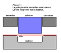
Deep drawing, raw part (red)

Deep drawing, finished part

Component produced by collar pulling


Tensile forming according to DIN 8585
Forming under prevailing tensile stress; Subgroups:
- Lengths , e.g. lengthening bars or sheets.
- Widening , for example widening of hollow bodies
- Depths , for example, hollow embossing of vehicle signs
Bending according to DIN 8586

Forming under prevailing bending stress; The bending can be used for plates, rods and tubes and is further divided in accordance with DIN:
- Bending forming with straight tool movement
- Bending forming with rotating tool movement
With straight movement ( Free bending here )

With rotating movement (here swivel bending )


Shear forming according to DIN 8587
Forming with prevailing shear stress.
- Twisting : With a rotating tool movement. Used for the production of drills, propellers.
- Move : With a straight tool movement. Used to make the cranks on crankshafts.

Twisting

Move


Further procedures
Productivity, flexibility and accuracy
Most forming technology processes are comparatively productive but imprecise. They are therefore used as a process suitable for mass production in order to roughly work out the shape of the finished components from the raw parts. In most cases, post-processing through more precise but less productive processes is then necessary, in particular through grinding .
The achievable accuracies stated as ISO tolerance are usually at IT16 to IT12 (small numbers are more accurate) (. Eg with precision variants precision forging ) also to IT8. With some processes such as cold extrusion , IT6 can also be achieved. The casting as an important competitive process is similar exactly thus, while the machining is a closer look at regularly to IT7 and precision variants IT6. The grinding even reaches up to IT1.
The achievable surface roughness ( roughness depths R z ) is usually between 1000 µm and 10 µm for forming, up to 4 µm for extrusion and up to 1 µm for rolling. Similar surface qualities can be achieved with casting. Machining, on the other hand, achieves a roughness of 2.5 µm to 1 µm, and grinding even up to 0.25 µm.
Some processes in forming technology use tools that already contain the shape of the work piece as a negative, including rolling and drop forging . These are very productive, but not very flexible, as different tools are required for a different workpiece shape. Other processes influence the shape of the workpiece through the movement of the tools, including open die forging , spinning and many bending processes. These are relatively flexible but unproductive.
machinery
The forming machines can be further subdivided according to the manufacturing process into bending machines , presses , drawing machines (for pulling through ) and rolling machines . However, several manufacturing processes can be implemented by installing different tools. Presses are basically suitable for open-die and closed-die forging and deep drawing. Therefore, a classification according to the underlying functional principle has proven itself. With energy-bound forming machines, the same amount of energy acts on the workpiece with each stroke. This can be done by always dropping the tool from a certain height, like a drop hammer . The top pressure and counter blow hammers as well as screw presses also belong to this group . Path-bound forming machines cover the same path with each stroke. These include eccentric presses , crank presses and toggle presses . Force-bound forces act on the workpiece until a certain force is reached. These include hydraulic presses .
Cutting machines are very similar in construction to the forming machines and are divided into guillotine shears , cutting presses and punching machines . They are mainly used for processing sheet metal , which serves as the starting material for subsequent forming, as well as for post-processing in drop forging (punching and deburring).
Calculation bases
Flow curves, yield stress and degree of deformation
In most areas of technology, the stress-strain diagram is used for the relationship between the change in shape of a body and the prevailing forces or tensions (force per area) . There the elongation (change in length in relation to the initial length) and the technical tension (force per initial cross-section) are used as variables .
These sizes have not proven themselves in forming technology. Instead, the flow curve is determined here, which provides a relationship between the degree of deformation and the flow stress .


- The yield stress is the stress that is necessary for plastic deformation. It is not related to the initial cross-section, but to the actually existing cross-section.
- The degree of deformation is the change in length, which is related to the existing change in length.
Flow curves and thus the flow stresses depend on several parameters. The most important are:
- the forming temperature
- the forming speed
- the material
Volume constancy
In forming technology, the workpieces are considered to be incompressible to a good approximation. The volume of the workpieces thus remains constant. For example, if the width of the blank is constant during rolling and its thickness is halved, then its length is doubled.
The degrees of deformation for the individual dimensions must therefore add up to zero:

The speed of the rolling stock also results from the constant volume: The volume of the raw part that enters between the rollers must also exit behind the rollers. If the sheet thickness is halved, the speed after the rollers doubles.
Forming speed
The forming speed indicates how fast the forming takes place. The yield stress usually increases with rapid deformation.

The following applies:

Forming work
The physical work required for forming a specific workpiece is required for production planning . Especially with energy-bound forming machines such as drop hammers , it is necessary to determine the number of strokes required, as a certain amount of energy is released with each stroke.
The ideal deformation work (without taking friction into account) can be calculated from the deformed volume , the average yield stress and the degree of deformation as follows:


- .

The real deformation work (with consideration of friction) obtained via the Umformwirkungsgrad to


- .

Experience has shown that the forming efficiency is between 0.4 and 0.8. It is determined experimentally, especially for workpieces with a complicated shape. It depends on the friction on the tool surfaces, the type of forming process, the formed material, the workpiece geometry and the material flow.
Forming force
Knowledge of the forming force is required for force-bound and path-bound forming machines in order to determine whether the planned workpieces can be processed at all. The maximum force is of particular interest here.
In the calculation, a distinction must be made as to whether the force is introduced directly or indirectly into the forming zone. In processes with indirect force introduction, the workpiece transfers the force from the point of contact with the tool to the forming zone. This includes deep drawing and drawing through . In the case of processes with direct force application, the forming zone is located directly at the force application point. This includes rolling and forging.
With direct force introduction, the ideal forming force (without taking friction into account) results from the flow stress and the cross-sectional area perpendicular to the force


- .

In the case of indirect force introduction, the ideal forming force results, together with the mean flow stress and the degree of deformation, as:
- .

See also
literature
- Hartmut Hoffmann , Reimund Neugebauer , Günter Spur : Handbook Forming , Hanser, 2012.
- Eckart Doege , Bernd-Arno Behrens : Handbook Umformtechnik , Springer, 2010, 2nd edition.
- Fritz Klocke , Wilfried König : Manufacturing process 4 - forming , Springer, 5th edition.
Individual evidence
- ↑ IPH - Overview of the processes in forming technology. In: process technology, production automation, logistics | IPH - Institute for Integrated Production Hanover. Retrieved February 12, 2018 .
- ↑ Eckart Doege, Bernd-Arno Behrens: Handbuch Umformtechnik - Basics, Technologies, Machines Springer, 2nd edition, 2010, p. 7.
- ↑ Eckart Doege, Bernd-Arno Behrens: Handbuch Umformtechnik - Basics, Technologies, Machines Springer, 2nd edition, 2010, p. 7.
- ^ [1] Fundamentals of Forming Technology Prof. Mauk, IAM-2005
- ↑ König, Klocke: Manufacturing processes - Volume 4: Umformen Springer, 5th edition, pp. 88–98, especially p. 88.
- ↑ König, Klocke: Manufacturing Processes - Volume 4: Forming Springer, 5th Edition, pp. 222f.
- ↑ Eckart Doege, Bernd-Arno Behrens: Handbuch Umformtechnik , Springer, 2010, 2nd edition, p. 259.
- ↑ Eckart Doege, Bernd-Arno Behrens: Handbuch Umformtechnik , Springer, 2010, 2nd edition, p. 259 f.
- ↑ Eckart Doege, Bernd-Arno Behrens: Handbuch Umformtechnik , Springer, 2010, 2nd edition, pp. 269–471.
- ↑ Alfred Herbert Fritz, Günter Schulze (ed.): Manufacturing technology , Springer, 9th edition, 2010, pp. 411, 419.
- ↑ Alfred Herbert Fritz, Günter Schulze (ed.): Manufacturing technology , Springer, 9th edition, 2010, p. 411, 445.
- ↑ Alfred Herbert Fritz, Günter Schulze (ed.): Manufacturing technology , Springer, 9th edition, 2010, pp. 411, 458.
- ↑ Alfred Herbert Fritz, Günter Schulze (Ed.): Manufacturing technology , Springer, 9th edition, 2010, p. 411, 463 f.
- ↑ Alfred Herbert Fritz, Günter Schulze (ed.): Manufacturing technology , Springer, 9th edition, 2010, p. 3.
- ↑ Weck, Brecher: Machine Tools - Volume 1 5th Edition, pp. 51–53.
- ↑ König, Klocke: Manufacturing Processes - Volume 4: Forming Springer, 5th Edition, p. 28.
- ↑ Alfred Herbert Fritz, Günter Schulze (ed.): Manufacturing technology , Springer, 9th edition, 2010, pp. 414, 416.
- ↑ Alfred Herbert Fritz, Günter Schulze (Ed.): Fertigungstechnik , Springer, 9th edition, 2010, p. 419.
- ↑ König, Klocke: Manufacturing Processes - Volume 4: Forming Springer, 5th Edition, p. 28
- ^ Alfred Herbert Fritz, Günter Schulze (ed.): Manufacturing technology , Springer, 9th edition, 2010, p. 417 f.
- ↑ Alfred Herbert Fritz, Günter Schulze (Ed.): Fertigungstechnik , Springer, 9th edition, 2010, p. 418.