
Voyager probes

The Voyager probes are two largely identical space probes from the US space agency NASA , which cross the outer planetary system as Voyager 1 and Voyager 2 . Since 1977 they have been collecting data from the outer solar system as part of the Voyager program .
Development history

The Voyager probes are the successors of the space probes of the "Thermoelectric Outer Planets Spacecraft" project (TOPS), which were canceled for cost reasons. From this, the designers adopted a number of the new technologies developed for TOPS. They hoped to extend their mission through these technologies. Construction of the two Voyager probes began in mid-1975.
construction
The Voyager probes essentially consist of a central, ring-shaped aluminum cell, which is decagonal in cross-section and houses a large part of the electronics. It has a diameter of 1.78 m and is 0.47 m high. A parabolic antenna with a diameter of 3.66 m is attached to it. Most of the scientific instruments are installed on a 2.5 m long boom. The central cell is built around the hydrazine tank and divided into ten individual compartments, each 0.43 m wide. Each probe has a total mass of 825.5 kg, 104.8 kg of which are scientific instruments.
electronics
Most of the electronic systems are housed in the central cell and are based on the architecture of the Pioneer 10 and 11 probes. The Voyager probes have three fully redundant computer systems that are responsible for communication ( Communication & Command System ; CCS), alignment, and orbit control ( Attitude and Articulation Control System ; AACS) and data storage ( Flight Data Subsystem ; FDS). These components are shielded by a sheath made of tantalum and titanium for radiation protection .
The CCS communication system was initially to be completely taken over by the Viking probes, although the performance of the latter was comprehensively increased due to the more demanding mission profile. 1.9 MHz clock it has a computing power of 0.73 MIPS , 64 times the Viking probes. The freely divisible ring core memory has a capacity of 4000 data words of 18 bits each . For the first time, a built-in self-test was installed on a probe , which is supposed to detect serious problems: loss of the receiver for commands, failure of the transmitter or the oscillator for the carrier wave , anomalies in the AACS, anomalies in the hardware or software of the CCS and unusual voltage or current fluctuations.


The AACS control system is required for the correct alignment of the probe and instruments due to the very high speeds during flyby. It has the same toroidal core memory as the CCS, but only has 5 percent of the computing power. The AACS has two operating modes: a gyro mode for the highly precise alignment of the instrument platform during flyby and a star mode for astronomical navigation . The gyroscopes show a deviation of 0.05 ° per hour after calibration. In star mode, one sun and one star sensor are used, which are attached to the tip of the parabolic antenna. The sun sensor is a potentiometer based on cadmium sulfide and has a measuring accuracy of 0.01 °. The star sensor is a photomultiplier tube with a cesium detector that is aimed at the star Canopus . Both instruments try to keep their reference objects in the middle of their field of view and therefore activate the thrusters from a deviation of 0.05 °.
Due to the high data rate, a separate subsystem was also required for their processing, the FDS. Instead of the usual toroidal core memory of the Viking probes, it uses a CMOS memory which was new at the time and which is more resistant to voltage fluctuations. With a capacity of 8000 data words, it is twice as large as the ring core memory variant and was therefore used by the CCS for complex operations. The direct memory access (DMA) possible with CMOS memory also significantly reduced the load on the processor (processing power 0.08 MIPS). Both FDS computers can work in parallel, but serious problems can arise in the event of a failure, as there is no longer a dedicated reserve system available. An FDS weighs 16.3 kg and requires 10 W of electrical power.
As the data obtained cannot be sent to earth immediately due to the limited transmission capacity, a mass storage system was installed. This is a 328 m long magnetic tape that can digitally store up to 536 Mbit (100 images). The maximum writing speed is 115.2 kBit / s and the reading speed is a maximum of 57.6 kBit / s.
power supply

For missions of this kind (large distance from the sun) solar cells are not suitable for supplying energy. Therefore, three came radionuclide used with silicon - germanium - thermocouples by spontaneous decays resulting heat directly into electrical energy converted. At the start, the batteries each contained 4.5 kg of plutonium-238 , an α-emitter with a half-life of 87.7 years. Each individual battery is located in a 39 kg beryllium case that is 50 cm long and 40 cm in diameter. At the time of launch, a DC voltage of 30 volts and an output of 470 watts were available. Due to the decay of the plutonium, the thermal output is reduced by 0.79% annually. As the temperature of the radionuclide battery falls, the efficiency also falls, and the thermocouples also age, so that the annual power loss is around 1.38%. Therefore, more and more scientific devices and functions have to be switched off in order to leave enough energy for the control and communication systems.
The batteries are attached to a boom so that the on-board electronics and the scientific experiments are influenced as little as possible by radiation. This applies in particular to the bremsstrahlung that occurs when the α-particles penetrate into the battery casing and which cannot be completely shielded.
communication

Virtually all communication with the probe via the striking parabolic antenna unwound, which is mounted on the central cell and of a graphite - epoxy is made. It has a diameter of 3.66 m and an antenna gain of 48 dBi in the X-band and 36 dBi in the S-band. Since it is only able to move to a limited extent, the probe must be precisely aligned with the earth in order to be able to establish a connection. Two frequency bands are used for data transmission : the S-band (2295 MHz) and the X-band (8418 MHz). There are two transmitters for both bands that cannot be operated in parallel (they primarily serve as a backup). Together they have a mass of 21.7 kg.
The S-band is only used for sending and receiving commands or small data packets, as the data rate is only 60 to 160 bit / s. The two transmitters have a radiation output of 9.4 and 28.3 watts each and were also used secondarily for illuminating planetary atmospheres. An antenna with a low antenna gain (7 dBi) is also available as a backup . Practically all scientific data is transmitted via the X-band, since a much higher data rate (2.5 to 115.2 kBit / s) is available here. The lowest possible transfer rate is 10 bit / s.
The Golay and Reed-Solomon codes have been implemented to correct errors . Despite the significantly higher data rates compared to previous missions, there were noticeably fewer transmission errors.

| designation | number | Energy demand | Dimensions |
|---|---|---|---|
| Passive transponder | 2 | k. A. | 4.7 kg |
| receiver | 1 | 4.3 W | k. A. |
| Antenna control system and interface |
1 | 0.9 W | 2.5 kg |
| Highly stable oscillator | 1 | 2.7 W. | 2.0 kg |
| Diplexer | 2 | 1.4 kg | |
| Telemetry - modulator | 2 | 5.7 W | 2.7 kg |
| "Command Detector Unit" | 2 | 5.4 W | 2.0 kg |
| S-band exciter | 1 | 2.4 W. | k. A. |
| S-band switching amplifier | 1 | up to 91.2 W. | 5.0 kg |
| S-band TWT amplifier | 1 | up to 86.4 W. | 5.1 kg |
| X-band TWT amplifier | 2 | up to 71.9 W. | 5.8 kg |
| Send / receive switch | 1 | 1.2 W | k. A. |
| cabling | 2.3 kg | ||
| Other circuits | k. A. | 3.5 kg | |
| Waveguide , coax | 1 | 2.1 kg | |
| Parabolic antenna | 1 | 50.9 kg | |
| Total mass | 105.4 kg |
Flight control
Eight fully redundant thrust nozzles, each with 0.89 N thrust, are used to control the position and course of the probe , which generate the necessary recoil through the catalytic decomposition of hydrazine . The corresponding tank is made of glass fiber reinforced plastic and is located in the middle of the central cell. It holds 90 kg of hydrazine and must be heated to prevent it from freezing. Four further thrust nozzles are available for regulating the roll axis, each delivering a thrust of 22.2 N. The precise control impulses are calculated by the AACS computer.
Scientific instruments
overview

The Voyager probes carry a total of eleven scientific instruments with a total mass of 104.8 kg, which is considerably more than in previous planetary missions. The instruments require a total of 90 watts of electrical power, of which 10 watts are used for the corresponding heating elements.
The instruments are divided into two categories: direct measurement (e.g. particle detectors) and remote sensing (e.g. cameras). All instruments in the latter category are attached to a movable scanning platform, which is located on a boom 2.5 m from the central cell. The platform can be precisely aligned to a specific point in space (e.g. planets) by several electric motors controlled by the AACS. The positioning accuracy is 2.5 mrad.
| instrument | Mass kg |
Consumption W |
Data rate bit / s |
|---|---|---|---|
| Cosmic Ray System (CRS) | 7.50 | 5.4 | |
| Imaging Science System (ISS) | 38.20 | 21.5 | 115200 |
| Infrared Interferometer Spectrometer (IRIS) | 19.57 | 12.0 | 1120 |
| Low-Energy Charged Particles (LECP) | 7.50 | 3.8 | |
| Photopolarimeter System (PPS) | 2.55 | 0.7 | 0.6 ... 1023 |
| Planetary Radio Astronomy (PRA) | 7.70 | 5.5 | 266 |
| Plasma Spectrometer (PLS) | 9.90 | 8.1 | 32 |
| Plasma Wave System (PWS) | 1.40 | 1.3 | 32 ... 115200 |
| Radio Science (RSS) | 44.00 | ||
| Triaxial Fluxgate Magnetometer (MAG) | 5.60 | 2.2 | 120 |
| Ultraviolet Spectrometer (UVS) | 4.50 | 3.5 |
Cosmic Ray System (CRS)

This instrument is used to study the solar wind and the radiation belts of the planets, especially that of Jupiter. It consists of three different particle counters that count the angle, number and energy of impacting particles. The high-energy particle detector (HET) can detect protons and ions with atomic numbers from 1 ( hydrogen ) to 30 ( zinc ) in the range from 6 to 500 MeV per nucleon . These particles severely damage electronic components, so the results were of great importance for future missions. The HET is made up of a total of 11 sensors that determine the energy of the particles from the depth of penetration. The measurement errors are between 5 and 7 percent. The electron detector (TET) works on the same principle and can detect electrons in the range from 3 to 110 MeV. The detector for particles with low energy (LET) also determines the energy with the help of the determined penetration depth and detects particles in the range from 1.8 MeV to 30 MeV.
Imaging Science System (ISS)

The ISS combines two optical cameras that work in the range of visible and ultraviolet light, namely a narrow-angle telephoto camera (NAC) and a wide-angle camera (WAC). Both instruments can expose images for 0.005 to 61 seconds .
The telecamera has a Cassegrain telescope with an aperture of 176.5 mm and a focal length of 1500 mm. The transmission of the optics is 60 percent and the theoretical resolution is 1.18 arc seconds . An 11 mm wide selenium sulfide- based vidicon tube is used for image acquisition . The sensor has 800 × 800 pixels. The sensor works in the spectral range from 280 to 640 nm (UV-B to red) and is equipped with orange, green, blue, violet and UV filters to obtain color and false color images . The camera weighs 22.06 kg and measures 25 cm × 25 cm × 98 cm.
The wide-angle camera uses a Petzval - refractor having a focal length of 202 mm and diameter of 57.2 mm a. It consists of six radiation-hardened lenses, one of which is used for dust protection. The transmission of the optics is 84%, and the theoretical resolution is 2.87 arc seconds, using the same sensor as the NAC. The only difference lies in the slightly smaller spectral range (400–620 nm), which is due to the filter properties of the lenses. The WAC also uses all the filters on the telecamera with the exception of the UV filter. There are also special filters for detecting sodium and methane . The camera weighs 13.30 kg and has the dimensions 20 cm × 20 cm × 55 cm.
At least 48 seconds are required to completely read out the image sensors, which are identical in both cameras. There are also modes that can increase this time by 10 times. In order to enable quick readout, only 10% of the pixels can be read out. The quantization is done with 8 bits.
Infrared Interferometer Spectrometer (IRIS)
The IRIS determines the temperature and atmospheric structure of planets and moons by evaluating their infrared emissions. In particular, it should measure the hydrogen- helium ratio on Jupiter and Saturn. It is a Cassegrain telescope with a diameter of 50.0 cm, a focal length of 303.5 mm and a field of view of 0.25 °. Two sensors are connected: an interferometer / spectrometer and a radiometer. The former works in the spectral range from 2.5 to 50 µm and achieves a spectral resolution of 0.094 µm. The radiometer determines the heat of observed objects and uses the spectral range from 0.33 to 2 µm for this. A neon radiation source, which emits monochromatic radiation of 585.2448 nm, serves as a reference . The IRIS is synchronized with the two cameras of the ISS and provides six measured values for a 48-second recording (1x readout speed).
Low-Energy Charged Particles (LECP)

This instrument is used to study electrically charged particles with low energy and thus complements the CRS, which studies particles with high energy. Two sensors are used for the measurement: the "Low Energy Particle Telescope" (LEPT) and the "Low Energy Magnetospheric Particle Analyzer" (LEMPA). They study the interactions of particles with the magnetic fields of moons and planets as well as cosmic rays and solar winds.
The LEPT analyzes electrons in the energy range from 0.01 to 11 MeV and protons from 0.015 to 150 MeV, whereby 10 −5 to 10 12 particles can be detected per second. The LEMPA only works near planets and moons. It detects alpha particles , ions and protons in the energy range 0.05 to 30 MeV. The two sensors are mounted one above the other so that they always examine the same area. They have a field of view of 45 ° and can be rotated through 360 ° by means of an 8 step motor , which takes at least 48 seconds. The motor should be able to perform a full rotation at least 500,000 times, which was already very ambitious for the state of the art at the time. Despite the expected wear problems, it had successfully completed over 5 million spins by 2008. Various types of sensors are used for measurements: semiconductor detectors with a thickness of 2 to 2450 µm, eight particle counters with a resolution of 24 bits and a pulse height analyzer with 256 channels. The calibration is carried out with a weakly radioactive source.
Photopolarimeter System (PPS)
The PPS measures polarization effects, which often arise from the interactions of light with matter. Since every substance behaves differently in this regard, conclusions can be drawn about the chemical structure of planetary surfaces, ring systems and atmospheres. The PPS has a Cassegrain telescope with a diameter of 20.32 cm, a focal length of 280 mm and a variable field of view from 0.12 ° to 3.5 °. It examines the polarization of light in 8 spectral ranges between 235 and 750 nm. A photomultiplier tube with a multi-alkali photocathode serves as the sensor . The incident light can be passed through up to eight different filters. A complete work cycle in which 40 measurements are carried out with different polarization and filter settings takes 24 seconds.
Plasma Spectrometer (PLS)
The PLS examines the behavior of the solar wind and of hot, ionized gases in open space as well as their interactions with the magnetic fields of the planets. It also analyzed the plasma field around Jupiter's moon Io and is able to determine the limit of the heliopause . To do this, it uses two sensors that work on the principle of Faraday's law . One detector is aligned with the earth and can detect electrons in the energy range from 4 eV to 6 keV, the other is perpendicular to it and measures in the range from 5 eV to 10 keV.
Plasma Wave System (PWS)

This instrument is particularly noticeable because of its two 10 meter long antennas, which lead away from the central cell at a 90 ° angle. They have a diameter of 1.27 cm each and are made of beryllium copper . The PWS uses it as a dipole antenna , which has an effective length of 7 m. The instrument examines the interactions of particles with the magnetic fields of the planets and the electrical component of plasma waves in the frequency range from 15 Hz to 56 kHz. The receiver (with an upstream 40 dbi amplifier) offers 16 different channels, whereby a noise filter eliminates the interference caused by the alternating voltage of the on-board systems at 2.4 and 7.2 kHz.
Part of the PWS is a frequency analyzer that can generate a complete spectrum every four seconds. The bandwidth is ± 15% for the lower frequency range and ± 7.5% for the high range. The data rate is very low at 32 bit / s. The other part of the PWS is a waveform analyzer , which was a major innovation in space travel at the time. The analysis of waveforms requires a relatively high number of measured values (28,800 per second), which results in a very high data rate of 115,200 bit / s. Since this data cannot be compressed or cropped, after leaving the Jupiter system, due to the ever decreasing transmission bandwidth, one was forced to first save the measurements on the tape drives and send them later.
Planetary Radio Astronomy (PRA)
This instrument uses the two antennas of the PWS as a monopoly . It receives radio waves from planets in the frequency range of 20.4 to 1300 kHz and 2.3 to 40.5 MHz.
Radio Science Subsystem (RSS)
The RSS also uses modules from other systems, in this case those of the communication system. During communication, it can measure the Doppler shift of the received signals and thus draw conclusions about the mass of nearby planets and moons. In another operating mode, X- and S-band are used simultaneously to determine different frequency shifts when passing through atmospheres or dust clouds. Their structure and chemical composition can be determined from the data obtained. However, communication is not possible in this mode. A highly stable transmission frequency is essential for good measurement results, which is why a particularly stable oscillator was installed, which can still produce a very precise frequency even after a long time.
Triaxial Fluxgate Magnetometer (MAG)
The MAG consists of four sensors that measure magnetic fields of different strengths in three directions. Two of them are placed close to the probe and measure strong magnetic fields up to a strength of 2 mT with an accuracy of 6 pT (1/10000 of the earth's magnetic field ). The two sensors for weak magnetic fields are attached to an eye-catching, 13 m long boom that weighs only 2.3 kg due to its very light beryllium alloy. The large distance is necessary to reduce interference from the magnetic field of the probe, its electronics and the radionuclide batteries. The maximum measurable magnetic field is around 500 µT, the maximum accuracy is 2 pT.
Ultraviolet Spectrometer (UVS)

This instrument performs the same analyzes as the IRIS, but in the high ultraviolet frequency range from 40 to 160 nm. It has essentially two operating modes. On the one hand, it can identify radiation sources in the atmosphere of moons and planets, and on the other hand, it can analyze the specific behavior of external UV radiation (for example the sun) when it travels through atmospheres. The UVS was also very important when the probe was not in the vicinity of celestial bodies. At that time there was no telescope, either on earth or in space, that covered the extremely high UV range. Hence, this instrument was used for many other scientific observations as well.
Voyager Golden Record

The "Voyager Golden Record" is a copper data disk that has been plated with gold to protect against corrosion . Image and audio information about humanity is stored on it. On the front there is a kind of instruction manual and a map that shows the position of the sun in relation to 14 pulsars .
Maintenance of the software
The probe software is still being further developed and maintained. At the end of 2015, NASA was looking for a successor to Larry Zottarelli, who was responsible for the probe software until then.
photos
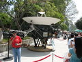
Full-size model of a Voyager probe

Ed Stone, 1972 Voyager probe scientist, later director of JPL , in front of a full-size model
The scan platform (detail drawing)
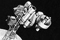
Voyager 1 in Space Simulator


literature
- Ben Evans: NASA's Voyager Missions . Springer-Verlag , London 2004, ISBN 1-85233-745-1 .
- Reiner Klingholz : Voyagers Grand Tour . Smithsonian Institute Press, 2003, ISBN 1-58834-124-0 .
- William E. Burrows: Mission to Deep Space: Voyager's Journey of Discovery . WH Freeman & Co. Ltd., 1993, ISBN 0-7167-6500-4 .
Individual evidence
- ↑ Bernd Leitenberger: Voyagers Mission: The Story .
- ↑ a b c d e f g h i j Bernd Leitenberger: Voyagers: The probe. Retrieved May 19, 2012 .
- ↑ a b c d e f g h i j k l m n o p Bernd Leitenberger: Voyagers instruments. Retrieved May 19, 2012 .
- ↑ NASA is looking for programmers for Voyager probes , Heise online , October 31, 2015.
- ↑ Why NASA Needs a Programmer Fluent In 60-Year-Old Languages , Popular Mechanics , October 29, 2015.
- ↑ NASA's last original Voyager engineer is retiring , CNN , October 27, 2015.
Web links
- Description of the Voyager probes
- Voyager project side of the NASA (English)
- Ulf von Rauchhaupt: Voyager probes: The longest journey , faz.net, September 5, 2017, accessed on September 6, 2017.
- Document on "Thermoelectric Outer Planets Spacecraft (TOPS)" on the NASA Technical Reports Server (PDF, English, 154.9 MB).