
Plastic film capacitor
Plastic film capacitors , also called film capacitors or Folkos for short , are electrical capacitors with insulating plastic films as a dielectric . For this purpose, the plastics are drawn into extremely thin foils in a special process, provided with electrodes and then wound as a coil or layered from individual layers to form a capacitor. After ceramic capacitors and electrolytic capacitors, they belong to the most frequently used capacitor types and are used in many areas of electronics and electrical engineering .


Structure and use
Plastic film capacitors usually consist of two plastic films as a dielectric, which are metallized or covered with metal foils, and the electrodes. Since plastic film capacitors, like almost all capacitors in electronics, are basically plate capacitors, the capacitance of which is greater, the larger the electrode area and the relative permittivity and the closer the electrodes are to one another


the thinner the dielectric, the greater the capacitance of a capacitor. For this reason, the foil base material is drawn into extremely thin foils in a special process , as long as the desired dielectric strength of the later capacitor allows it. The coated foils are wound into a roll, contacted on the side surfaces, provided with the connections and protected against external influences with a cover.
As a result of the contacting of the electrodes on the end faces of the capacitor winding, which is common today, the entire power supply to the two electrodes is kept very short. There is no current flow around the coil. This reduces the internal ohmic losses ( ESR ) and the parasitic inductance of the capacitor ( ESL ). Today's plastic film capacitors have very low ohmic losses and a very low parasitic inductance due to their design, which makes them especially suitable for applications in the higher frequency range, for blocking voltage peaks and high ( interference ) pulses or for steep pulse edges or high pulse current loading capacity are suitable, e.g. B. as snubber capacitors in power electronics.
Typical capacitance values of plastic film capacitors start at a few 100 picofarads and extend into the microfarad range; the dielectric strength , depending on the design, starts at 40 V and extends into the four-digit volt range. The designs and sizes are correspondingly diverse: from a few cubic millimeters to the power capacitors in meter-sized dimensions.
Metallized plastic film capacitors have self-healing properties; breakdowns do not destroy the component. This makes them well suited as interference suppression capacitors parallel to the mains voltage (X capacitor) or against earth, housing ground or touchable parts (Y capacitors).
Another characteristic of plastic film capacitors, especially of film capacitors with a polypropylene film as a dielectric, is the comparatively low temperature dependence of the electrical values. That is why they are often found as so-called “class 1 capacitors” in frequency-determining elements of oscillator circuits .
Manufacturing
In the case of plastic film capacitors, a distinction is made between two types due to different electrode designs:
- Metal foil capacitors, also known as plastic foil capacitors with metal coatings, consist of two metal foils as an electrode and two interposed plastic foils as an insulator. They have the highest current pulse load capacity of all known capacitors.
- Metallized plastic film capacitors: With them, metallizations applied directly to one or both sides of the insulating film represent the electrode. They have self-healing properties. With suitable constructions, this can also apply to special metal foil capacitors.

- Metallization: The plastic material is first drawn into extremely thin foils in an extrusion process in a bi-axial direction.Then this foil is metallized with aluminum or zinc in a vacuum vapor deposition system in a high vacuum at around 10 15 to 10 19 air molecules per cubic meter (layer thickness ~ 0, 03 µm). These metallized foils are about one meter wide and are called “parent rolls”.
- Foil cutting: The parent rolls are cut to the required width according to the size of the later capacitors.
- Wrap: The foils are rolled into a roll. The two metallized foils that belong to a capacitor are wound slightly offset from one another, so that due to the offset arrangement of the electrodes, one edge of the metallization protrudes from one of the two side surfaces (end faces) of the winding.
- Flattening: The winding of the later capacitor is brought into an oval shape by pressure (flattening). This reduces the projection area of the component on a circuit board and reduces costs due to the lower number of circuit board requirements.
- Contact: The protruding electrodes are metallized ( schooped ) with tin , zinc and / or aluminum using a process named after Max Ulrich Schoop , i.e. electrically contacted. The contact metal is liquefied and sprayed directly onto the respective face of the condenser as a finely distributed mist with the aid of compressed air.
- Healing: The wrap, which can be electrically contacted through the shooping, is "healed". A suitable (high) voltage is applied to the roll and any defects in the roll are thereby "burned away", i.e. H. healed (see also " self-healing " below).
- Impregnation: For increased protection against environmental influences, the wraps can be impregnated after they have healed, e.g. B. with a silicone oil or a silicone varnish.
- Welding the connections: The connections are soldered or welded to the contact layer of the winding end faces.
- Casing: After attaching the connections, the capacitor cell is placed in the desired housing or provided with a protective coating. For reasons of lower manufacturing costs, however, film capacitors are also used without further wrapping the roll.
- Final inspection: During the final electrical inspection, every capacitor is 100% tested for compliance with the specified capacitance value, dissipation factor and impedance .

Plastic film capacitors with metal foils are produced in a similar way. Here, only the metal foils are wrapped between the plastic foils during winding.
The windings of film capacitors are usually made in the shape and size of the later capacitor. Another manufacturing option is to wind the roll on a core with a large diameter and saw out individual segments from it. In the case of metallized plastic films, this manufacturing process allows the inexpensive manufacture of so-called multilayer capacitors (MLP, multilayer polymer capacitors) or “stacked” film capacitors, whereby the structure destroyed by the sawing on the cut surfaces is healed in the course of further production.
Constructive options for increasing the dielectric strength

In technical terms, the dielectric strength of plastic film capacitors results from the thickness of the plastic film, the dielectric. For example, the minimum available film thickness of 0.7 µm for polyester films is sufficient to produce capacitors with a nominal voltage of 400 V DC. If higher nominal voltages are required, a thicker film can be used or by creating an internal series connection of interconnected individual capacitors by partially metallizing the insulating film. As a result, the dielectric strength of the overall capacitor is multiplied, but the capacitance is reduced to a corresponding fraction. This has advantages over a thicker film:
- the breakdown voltage of a film does not increase linearly with the thickness in the case of direct voltage due to possible inhomogeneous field distribution (see also dielectric strength )
- the use of partial discharges that damage the insulating material is shifted towards higher alternating voltages
In addition to the possibility of being able to increase the dielectric strength of the capacitor using foils that are partially metallized on one side, higher dielectric strengths are often also achieved with foils coated on both sides. These, too, can be joined together to form internal series circuits through partial coating. These constructions are widely used, especially in professional applications with polypropylene films.
- Increasing the dielectric strength of film capacitors through double-sided metallized films

MKP capacitor with double-sided coating

High voltage capacitor with an internal series connection of two capacitors

High voltage capacitor with internal series connection of four capacitors


Increase in impulse stability
In order to receive or emit high voltage or current pulses, capacitors have to withstand temperature increases. This refers to the contact areas of the metallization of the electrodes. The contacting consists of a large number of point-like contacts, which represent the critical area of the capacitor's internal resistance . The flow of current generates heat in these contact points in particular, which can lead to temperatures that are so high that the contact can burn off. A second limitation of the current carrying capacity can be seen in the thickness of the electrodes. In the case of metallized plastic film capacitors, which work with layer thicknesses of 0.02 to 0.05 μm, the current-carrying capacity is also limited by these thin layers.
On the other hand, the film capacitors owe their design anyway (compared to other capacitor technologies) high pulse resistance. The winding or layering technology makes contact with the electrodes on the end faces of the winding package via the loop. As a result, a large number of individual capacitors are connected in parallel, so to speak; Their ohmic and inductive losses, which are reflected in the equivalent series resistance (ESR) and the equivalent series inductance (ESL) (see capacitor, inductance and series resistance ), are also connected in parallel. The total ohmic capacitor losses decrease, and the inductance, which limits the rate of rise of a pulse, also decreases. The inductance is roughly proportional to the width of the capacitor.

In terms of design, the pulse resistance of plastic film capacitors can be influenced by various measures. Since the one-sided metallization of the plastic film is the cheapest way of forming the electrodes in the capacitor, which already has a very high pulse load capacity compared to other capacitor technologies, the contact resistance can be reduced, for example, by strengthening the metallization in the contact area. This increases the current carrying capacity and thus the pulse load capacity without losing the self-healing ability of the metallization. In addition, the foils can also be metallized on both sides. The total flow for a slide is divided into two branches. This doubles the permissible current density and pulse strength. In addition, this construction halves the inductance of the capacitor, because in principle two inductances are connected in parallel, which in turn enables faster pulses (i.e. larger).

The film, which is vapor-coated on both sides, is field-free because of the same potential on both sides and does not contribute to the capacity. It can therefore not be made of the dielectric film from a cheaper material such. B. in polypropylene film capacitors made of a polyester film, which is not only cheaper, but also thinner and thus contributes to the reduction of the capacitor. Because film capacitors with a film that is vapor-deposited on both sides are somewhat larger in volume than capacitors with a film that is vapor-deposited on one side, and every opportunity to reduce the size of the component is used. In contrast to metal foil capacitors, foil capacitors with foil vapor-deposited on both sides also have self-healing properties.
Foil capacitors, the electrodes of which are made of metal foils, have the highest pulse load capacity. With this construction, the contact resistance is lowest in the area of the Schoopierung. The metal foil capacitor is, however, the most expensive and large-volume solution, since metal foils can only be manufactured down to about 25 µm.

Self-healing metallized plastic film capacitors


Metallized plastic film capacitors are self-healing; In other words, in the event of a short-circuit between the metallized electrodes, due to the high arc temperature, both the dielectric in the breakdown point and the metallic foil coatings, which are only about 0.02 to 0.05 μm thick, evaporate in the vicinity of the breakdown point. The cause of the short circuit is literally burned away, with the resulting vapor pressure also blowing out the arc of the short circuit. The property of self-healing allows a single-layer winding of the metallized foils without additional protection against imperfections and thus leads to a reduction in the required construction volume.
The ability of metallized plastic films to self-heal is exploited several times during the manufacturing process of these capacitors. After cutting the metallized foils to the desired width, any defects that may have arisen are burned out (healed) by applying a suitable voltage before winding and any defects that may have arisen in the capacitor are also healed using the same method after the shooping.
The "holes" in the metallization caused by self-healing reduce the capacitance of the capacitor. The magnitude of this reduction is, however, quite small, even with a few thousand burned-out defects, this reduction will usually be significantly less than 1% of the total capacity.
For larger plastic film capacitors where very high demands are placed on the stability of the characteristic values and on a very long service life, such as B. on intermediate circuit capacitors in inverters for wind turbines , the metallization can also be done in certain patterns ( textures ). In the picture on the right, such a pattern is shown in "T" shape. This type of metallization in a strip-shaped structure has only a very small conductor track cross section in the area of the power supply to the electrode strip. In the event of a breakdown between the electrodes, a current flows over this cross section, which immediately vaporizes this area; it acts like a fuse . This significantly limits the short-circuit current in the area of the arc and thus also the effects in the capacitor.
materials
Plastic film capacitors are usually only made with a single film material as the dielectric. Some plastics have particularly proven themselves here. The following table lists the plastics most commonly used today for film capacitors.
| dielectric | Chemical short name |
Brand name | Code letter |
|---|---|---|---|
| Polyethylene terephthalate, polyester | PET | Hostaphan , Melinex , Mylar | T |
| Polyethylene naphthalate | PEN | Kaladex | |
| Polyphenylene sulfide | PPS | Torelina | |
| Polypropylene | PP | Kopafilm, Treofan | P |
| Polytetrafluoroethylene | PTFE | Teflon | |
| Polystyrene | PS | Styroflex | S. |
| Polycarbonate | Pc | Macrofol | C. |
The plastic films are only produced by one or two major suppliers worldwide. The reason for this is that the overall quantities required by the market are quite small. This results in a great dependency of the capacitor manufacturer on the large chemical industry. For example, the production of polycarbonate film, which Bayer AG stopped in 2000 due to insufficient sales or too low prices, led to high costs for device manufacturers who had to convert their products to a different type of capacitor.
The most commonly used plastic films are polyethylene terephthalate , (polyester) and polypropylene . Polyethylene naphthalate , polyphenylene sulfide are used for some high temperature applications. Polytetrafluoroethylene film capacitors are only manufactured for very special high temperature applications. Plastic film capacitors with polycarbonate film are only built by a few, mostly American manufacturers. Polystyrene film capacitors have largely been replaced by polypropylene film capacitors.
So-called mixed dielectrics can also be used to achieve special properties of the capacitors. These consist of two or more different materials that are wrapped on top of each other.
Designs
Plastic film capacitors are manufactured in the designs customary in industry. The previously common axial design was replaced in the 1970s and is rarely found. The most common today is the radial design with soldered connections on one side. Due to the assembly technology with their standardized hole spacing in the 2.5 mm grid, radial plastic film capacitors are usually manufactured with a connection spacing that is a multiple of this value. You get these radial capacitors in a cup design, i. In other words, the wrap is built into a plastic cup and encapsulated and thus largely protected against the effects of moisture and can be installed in a stable manner, as well as in a painted version and also as a so-called "naked wrap" without additional protection. The latter version is used in devices with low environmental impact for reasons of lower costs.
Plastic film capacitors are also available as components for surface mounting ( surface mounted device , SMD). These "SMD film capacitors", in which, instead of the connecting wires, areal connections contact the film roll, are also offered for the increased soldering conditions of lead-free soldering.
In addition, plastic film capacitors are also supplied with special connections, for example the so-called “ snubber ” capacitors, where the current carrying capacity of the connections must be able to cope with the very high current pulses in the IGBT circuit.
- Types of plastic film capacitors

SMD design, film capacitor for surface mounting.

Axial design, film capacitors for horizontal mounting.

Radial design, film capacitors with soldered connections in grid spacing for upright installation.
The design for "snubber" capacitors has wide flat connections for maximum current carrying capacity


The pictures of the designs only show plastic film capacitors for electronic circuits and for low-power electrical circuits. Interference suppression capacitors and power capacitors for power engineering applications are not shown here.
history
Plastic film capacitors are a further development of layered or wound and impregnated paper capacitors with metal foil coverings or metallized paper foils. Paper capacitors have been manufactured since 1876 and 1900 and were used as so-called block capacitors in the early days of communication technology (telephony). As metal-paper capacitors (MP capacitors), they can still be found today as radio interference suppression capacitors or in power electronics.
With the development of plastics in organic chemistry, the capacitor industry began to replace the paper in paper capacitors with thinner and more stress-resistant plastic films after World War II. The plastics polyester (PET) and polypropylene (PP), for example, were produced in large quantities for the first time at the beginning of the 1950s, polycarbonate (PC) followed in 1953. The introduction of the plastics in plastic film capacitors took place in the following order: polystyrene , polyester, cellulose acetate ( CA), polycarbonate, polytetrafluoroethylene , polyparaxylylene , polypropylene, polyethylene naphthalate and polyphenylene sulfide (Roe-22-79). By the mid-1960s, a wide range of different plastic film capacitors had been developed that were offered by many manufacturers. Manufacturers in the German-speaking area such as WIMA , Roederstein , Siemens and Philips were trendsetters and leaders in the world market.
One of the great advantages of plastic films for capacitor production was that they had considerably fewer imperfections in the material than the paper used for the paper capacitors. This enabled plastic film capacitors to be wound with just one layer of plastic film. Paper capacitors, on the other hand, always require a double-layer paper winding. Plastic film capacitors therefore had significantly smaller dimensions than paper capacitors with the same capacitance and dielectric strength from the start.
A special feature in the development of plastic film capacitors were the cellulose acetate film capacitors, also known as MKU capacitors. The polar insulating material cellulose acetate, a synthetic resin varnish, could be produced for metallized varnish capacitors in layers of up to 3 µm. That was a possibility to reduce the thickness of the dielectric compared to other plastic film capacitors in order to get smaller designs. For this purpose, the paint was first applied to a backing made of smooth (waxed) paper, dried and then metallized; only during the winding process was the backing paper peeled off the metallized film and discarded. With this thin layer thickness, which was not achieved by the other plastic films at the time, film capacitors with a very high specific capacitance at the time could be produced. The result was a relatively small design at the time, but the dielectric strength of 63 V was also quite low. CA film capacitors are no longer manufactured because polyester film capacitors can now be manufactured in smaller designs.
The new plastics also showed no signs of chemical changes in their long-term behavior, so they offered excellent long-term stability of the electrical properties. In addition, the new plastics had less hygroscopic properties than paper, which meant that the housing of the capacitors could also be made from the new, inexpensive plastic materials instead of more expensive metal cups.
The capacitors, which were new at the time, also offered some improvements over other capacitor technologies. They proved to be highly resilient and insensitive to current impulses, especially the versions with metal coatings. Some types of film are also suitable for resonant circuit applications due to their low and almost linear electrical losses over a very wide frequency range. Both were previously only possible with ceramic capacitors . For simple filter circuits , the polyester capacitors in particular offered inexpensive solutions with high long-term stability, which meant that smaller electrolytic capacitors could be replaced.
From the simple beginnings, a very broad and highly specialized range of plastic film capacitors has developed which, in wired technology, is on an equal footing with the two other major capacitor technologies, ceramic and electrolytic capacitors, and which in terms of constancy of electrical values, quality and Security meets requirements in many areas that are difficult or impossible to achieve with other technologies.
In terms of miniaturization, film capacitors have also made considerable progress compared with the beginning of film technology. The development of ever thinner plastic films made it possible to increase a given capacitance / voltage value of a metallized polyester film capacitor by a factor of 10 with the same dimensions.
In the power grid , in electrical systems, for example as starting capacitors or for reactive current compensation, as well as in resonance converters at frequencies up to the MHz range (including inductive heating ), plastic film capacitors, here called power capacitors, are used.
market
Today, essentially only five plastics are used as foils for capacitors: PET, PEN, PP, PPS and occasionally PTFE. The other plastics are no longer in use because they have been replaced by better materials or, as in the example of polycarbonate, the manufacturer of the material has stopped supplying PC films. The film capacitors with polystyrene and polycarbonate films, which were widely used for a long time, have also been largely replaced by the types of film mentioned above.
The quantitative distribution of the different plastic films for film capacitors (deliveries from the film manufacturer to the capacitor manufacturer) in the film area supplied was in 2006: polypropylene (PP) = 55%, polyester (PET) = 40%, polyphenylene sulfide (PPS) = 3%, polyethylene naphthalate ( PEN) = 1% as well as other foils (PTFE, PVDF, siloxanes) = 1%.
In the beginning, plastic film capacitors were mainly produced in the United States and Germany, but towards the end of the 20th century there was a consolidation of the market and some production was also relocated to the Far East.
The world's largest manufacturers of plastic film capacitors are:
- WIMA , leading supplier on the world market for professional film capacitors
- Epcos , part of TDK Corporation since 2009
- Vishay including Roederstein and BCc
- KEMET Corporation , to which Evox Rifa and the Arcotronics Nissei Group have also belonged since 2007
- Panasonic
- Hitachi AIC Inc.
Only a few manufacturers of film capacitors remained in Germany. FRAKO
Properties of the plastic films
The electrical properties, the temperature and frequency behavior of plastic film capacitors are essentially determined by the type of film that forms the dielectric of the capacitor. The following table lists some significant material properties of the most important plastic films used today. Properties of mixed dielectrics cannot naturally be listed here.
The information in this table comes from various manufacturers and applies to plastic film capacitors for electronic applications. Electrical values of power capacitors were not taken into account. The wide range of values for the loss factor includes both typical and maximum information in the data sheets of the various manufacturers.
| Foil material | |||||
|---|---|---|---|---|---|
| Foil short name | PET | PEN | PPS | PP | |
| Dielectric constant at 1 kHz | 3.3 | 3.0 | 3.0 | 2.2 | |
| Min. Film thickness in µm | 0.7 | 0.9 | 1.2 | 1.9 | |
| Moisture absorption in% | low | 0.4 | 0.05 | <0.1 | |
| Dielectric strength in V / µm | 580 | 500 (?) | 470 | 650 | |
| Type. Nominal voltage range (V DC ) in V | 50 ... 1000 | 16 ... 250 | 16 ... 100 | 40 ... 2000 | |
| Type. Capacity range | 100 pF… 22 µF | 100 pF… 1 µF | 100 pF ... 0.47 µF | 100 pF… 10 µF | |
| Max. Operating temperature in ° C | 125/150 | 150 | 150 | 105 | |
| ΔC / C over temperature range in% | ± 5 | ± 5 | ± 1.5 | ± 2.5 | |
| Loss factor (· 10 −4 ) | at 1 kHz | 50 ... 100 | 42 ... 80 | 2… 15 | 1… 5 |
| at 10 kHz | 110… 150 | 54… 150 | 2.5 ... 25 | 2… 8 | |
| at 100 kHz | 170 ... 300 | 120 ... 300 | 12 ... 60 | 2… 25 | |
| at 1 MHz | 200 ... 350 | - | 18 ... 70 | 4… 40 | |
| Time constant R Iso · C in s | at 25 ° C | ≥10,000 | ≥10,000 | ≥10,000 | ≥100,000 |
| at 85 ° C | 1,000 | 1,000 | 1,000 | 10,000 | |
| Dielectric absorption in% | 0.2 ... 0.5 | 1… 1.2 | 0.05 ... 0.1 | 0.01 ... 0.1 | |
| Max. Spec. Capacity in nF · V / mm 3 | 400 | 250 | 140 | 50 | |
Polyester film capacitor

The polyester film capacitor is a plastic film capacitor with the thermoplastic, polar plastic polyethylene terephthalate (PET) from the polyester family as the dielectric.
Polyester film capacitors are inexpensive bulk capacitors in modern electronics and have relatively small dimensions with comparatively high capacitance values. They are mainly used for DC voltage applications.
The temperature dependence of the capacitance of polyester film capacitors is relatively high at ± 5% over the entire temperature range in comparison with the other film capacitors. The frequency dependence of the capacitance of the polyester film capacitors is -3% in the range from 100 Hz to 100 kHz in comparison with the other film capacitors at the upper limit. When it comes to the temperature and frequency dependency of the loss factor, polyester film capacitors also have higher deviations compared to the other film capacitors. Because of the higher dielectric constant and the higher dielectric strength of the polyester film, smaller designs can be implemented for a given capacity and nominal voltage.
The polyester film is equally suitable for film capacitors with metal coverings as well as for metallization. It hardly absorbs any moisture and, in mild climatic conditions, is therefore also suitable for designs that do not require an additional cover. Metallized polyester film capacitors are manufactured both as wound capacitors and as stacked film capacitors , which have been sawn out of a large roll.
Polyethylene naphthalate film capacitor
Polyethylene naphthalate film capacitors are plastic film capacitors with the biaxially aligned thermoplastic insulating material polyethylene naphthalate (PEN) as the dielectric. Polyethylene naphthalate also belongs to the polyester family with great chemical similarity to polyethylene terephthalate (PET), but has a higher temperature resistance.
PEN film capacitors have similar electrical properties to PE film capacitors in terms of temperature and frequency dependence of the capacitance and the dissipation factor. Because of the lower dielectric constant and the lower dielectric strength of the PEN film, however, PEN film capacitors have larger designs for a given capacitance and nominal voltage value. For this reason, PEN film capacitors are preferred when the temperature load during operation of the capacitors is permanently above 125 ° C. The main areas of application are screening, coupling and decoupling in electronic circuits. Due to the high temperature resistance, PEN film capacitors are also well suited for designs for surface mounting.
Polyphenylene naphthalate film capacitors with metal coatings are not manufactured.
Polyphenylene sulfide film capacitor
Polyphenylene sulfide film capacitors are plastic film capacitors with the semi-crystalline and high temperature resistant thermoplastic polyphenylene sulfide (PPS) as the dielectric.
The temperature dependence of the capacitance of PPS film capacitors is very small at ± 1.5% over the entire temperature range in comparison with the other film capacitors. The frequency dependence of the capacitance of the PPS film capacitors is also very low, at ± 0.5% in the range from 100 Hz to 100 kHz, compared to the other film capacitors. The loss factor of PPS film capacitors is quite small and the temperature and frequency dependence of the loss factor is almost zero over a wide range, i.e. H. very stable. The loss factor only increases more at temperatures above 100 ° C.
Polyphenylene sulfide film capacitors are well suited for applications in frequency-determining circuits. Because of their good electrical properties, they are an ideal replacement for polycarbonate film capacitors, the production of which has largely been discontinued since the year 2000.
In addition to the very good electrical properties, PPS film capacitors can also withstand temperatures of up to 270 ° C without impairing the film quality, so that they are also suitable for SMD designs that have to withstand the increased reflow soldering temperatures of RoHS- compliant lead-free soldering.
Polyphenylene sulfide film capacitors with metal coatings are not manufactured.
Polypropylene film capacitor

Polypropylene film capacitors are plastic film capacitors with the partially crystalline, non-polar thermoplastic insulating material polypropylene (PP) from the polyolefin family as the dielectric. Polypropylene films can be made quite thin (3 µm) by stretching processes in two axes without any loss of stability. Most polypropylene film capacitors are mentioned with these "BOPP" biaxially-oriented polypropylene films ( Biaxially oriented polypropylene (BOPP) manufactured).
Polypropylene film capacitors have a very low temperature and frequency dependence of the electrical parameters. The temperature dependency of the capacitance of PP film capacitors is rather low at ± 2.5% over the entire temperature range compared to other film capacitors. The frequency dependency of the capacitance of the PP film capacitors is the lowest with ± 0.3% in the range from 100 Hz to 100 kHz and ± 1% in the range from 100 Hz to 1 MHz compared to other film capacitors.
For polypropylene film capacitors with metal coatings, the stability of the capacitance value can also be influenced by special design measures, so that these capacitors can also be supplied in different so-called "stability classes".
| Stability class |
Temperature coefficient (α) and tolerance in ppm per Kelvin 10 −6 / K |
Permissible change in capacity Upper category temperature |
|||||
|---|---|---|---|---|---|---|---|
| −80 | −100 | -125 | -160 | -250 | 85 ° C | 100 ° C | |
| 1 | ± 40 | ± 50 | ± 60 | ± 80 | ± 120 | ± (0.5% + 0.5 pF) | ± (1% + 0.5 pF) |
| 2 | - | ± 100 | ± 125 | ± 160 | ± 250 | ± (1% + 1 pF) | ± (1% + 1 pF) |
| 3 | - | - | - | ± 160 | ± 250 | ± (2% + 2 pF) | ± (5% + 2 pF) |
This table only applies to capacitance values greater than 50 pF
In addition to the very good capacitive behavior, the loss factor of PP film capacitors is also smaller than that of the other film capacitors and the temperature and frequency dependence of the loss factor is almost equal to zero over a wide range, i.e. H. very stable. Therefore, polypropylene film capacitors are suitable for applications in frequency-determining circuits, filters, oscillator circuits, audio circuits and timers and for applications in the range of high frequencies. For these precision applications, they are available with very tight capacity tolerances.
Due to the low loss factor compared to other plastic films, even at very high frequencies and the high dielectric strength of 650 V / µm, film capacitors with polypropylene film are also used for pulse applications, e.g. B. in the line deflection circuit in tube TV sets or as so-called " snubber " capacitors.
A large area of application for polypropylene film capacitors are radio interference suppression capacitors , which are capacitors for reducing interference in radio reception, which are subject to special requirements with regard to safety and non-flammability.
In addition, polypropylene film capacitors are used in AC applications, e.g. B. used as engine start or engine running capacitors. Even the largest capacitors in terms of dimensions, the power capacitors, now mostly use polypropylene foils as dielectric. Here you can find both pure PP film capacitors and oil-soaked PP film capacitors and PP / paper film capacitors in large electrical systems. The AC voltage resistance of such power capacitors can reach up to 400 kV.
Polypropylene film is equally suitable for film capacitors with metal coverings as well as for metallization. It absorbs less moisture than polyester film and, in mild climatic conditions, is therefore also suitable for designs that do not require an additional cover. Metallized polypropylene film capacitors are manufactured both as wound capacitors and as film capacitors that have been sawn out of a large winding.
Polytetrafluoroethylene film capacitor
Polytetrafluoroethylene film capacitors are plastic film capacitors with the fully fluorinated polymer polytetrafluoroethylene (PTFE) as the dielectric. PTFE is also known as Teflon®.
PTFE film capacitors are characterized by a particularly high temperature resistance up to 200 ° C, with a voltage load reduction ( derating ) even up to 260 ° C. The loss factor is small at 1… 2.5 · 10 −4 even at high frequencies and the change in capacitance over the entire temperature range is comparable to that of polypropylene film capacitors. PTFE has low water absorption, high tracking resistance and is robust against corona discharges because it does not decompose through ultraviolet. It is therefore an extremely reliable dielectric. The dielectric absorption of PTFE film capacitors is lower than that of all other film capacitors, so these capacitors are well suited for analog circuits. The fact that the foils are difficult to metallize and tear easily makes them difficult to process. Therefore, because of the small number of pieces and because of the raw material price per se, PTFE film capacitors are very expensive.
PTFE film capacitors are available with metal foil and as metallized film capacitors. They are used z. B. in military devices, geo-probes and in so-called high-end audio devices. Because of these very special areas of application, of which the military is the most important, PTFE film capacitors are only manufactured in small numbers and assortments.
Plastic film capacitor with mixed dielectric
In addition to the above-mentioned and mainly used plastic films, mixed dielectrics are also used for capacitors. The "MKV" film capacitor is known here, which is constructed with a mixed dielectric consisting of a paper film metallized and impregnated on both sides as the electrode and a polypropylene film as the dielectric and is suitable for very high power losses. However, since almost every major manufacturer offers its own solutions for plastic film capacitors with mixed dielectrics, a general overview cannot be given here.
Styroflex film capacitor

Styroflex (trade name) is a copolymer of polystyrene and butadiene . Foil capacitors with Styroflex foil as a dielectric offer high capacitance constancy, low loss factor and low leakage currents. Until about 1990, these capacitors were widely used. Since the film thickness cannot technically be reduced far below 10 µm and the operating temperature only reaches a maximum of 85 ° C, they were then largely replaced by polyester film capacitors. Because of its good electrical properties, this type of capacitor is still manufactured in small quantities. Styroflex capacitors must be carefully processed by hand, as the Styroflex melts slightly under the heat of soldering.
Polycarbonate film capacitor
Polycarbonate film capacitors are film capacitors with the polymerized ester of carbonic acid and Dioxidiphenylpropane as a dielectric. They have been manufactured since the mid-1950s and, because of their relatively temperature-independent electrical properties, have many applications in areas with robust environmental conditions. The capacitors have a relatively low dependence of the capacitance on the temperature and a small loss factor. They are mainly used in timing circuits, precise analog circuits and filter circuits.
The main supplier of the polycarbonate film for capacitors stopped the production of this film in the year 2000, so that as a result the production of PC film capacitors was largely stopped worldwide. However, there are exceptions, for example:
Other plastics for film capacitors
In addition to the plastic films mentioned above, other thermoplastic materials are also mentioned in the literature as dielectrics for film capacitors. Because, among other things, the relatively small dielectric constant (DZ) of the above polymers of 2.2 to 3.3 mean that the capacity per volume of the "Folkos" is quite small compared to the other capacitor technologies, new thermoplastic polymers are constantly being created examined and described. Among them are
- Polyamides (PA), better known as nylon or perlon, DZ about 4 ,.
- Polyimide (PI), trade name Kapton, DZ = 3.5, this material is also interesting for special applications because of its temperature resistance up to 400 ° C. The “Kapton Capacitor” from the manufacturer YEC found in a Google search is, however, a double-layer capacitor and not a film capacitor.
- Polyvinylidene fluoride (PVDF), DZ = 18 to 50, the Curie temperature of only 60 ° C stands in the way of general use as a dielectric, but special applications are such. B. described as a storage capacitor for defibrillators .
- Polysulfone (PEx), trade name Ultrason, DZ = 3.3 and
- Aromatic polyester (FPE), trade name Vectran, DZ = 3
Plastic film capacitors with dielectrics made from these thermoplastic materials will not be offered in series by any manufacturer in 2012.
Plastic film capacitors for special applications
Interference suppression capacitors

An important application of plastic film capacitors and an important sales driver, especially of metallized polypropylene film capacitors, are interference suppression capacitors .
Interference suppression capacitors are capacitors to improve electromagnetic compatibility . They divert high-frequency interference signals from electrical or electronic equipment to ground or short-circuit them, thereby reducing their level. In addition, interference suppression capacitors protect the device from overvoltages (transients) or have to withstand these transients if they are connected to the mains .
Electrically, interference suppression capacitors must be designed so that the remaining interference signals do not exceed the prescribed limits of the EMC directive EN 50081 (EN 132400). In addition, since they can endanger people or animals from electric shock and fire in the event of a failure due to a short circuit, they have special requirements with regard to dielectric strength and non-flammability.
Interference suppression capacitors are divided into X and Y classes, whereby X capacitors are parallel to the mains and Y capacitors may be switched to earth or to accessible parts. Accordingly, X-capacitors only have to be permanently operational and must not cause any fires, Y-capacitors, however, must not break down under any circumstances. The conditions for the tests and measurements of the electrical and mechanical parameters for the approval of the radio interference suppression capacitors are specified in the standard DIN IEC 60384-14. Interference suppression capacitors can be identified by the imprint of the many test seals or test marks of the individual national safety organizations.
In terms of structure, interference suppression capacitors with polypropylene film do not differ significantly from MKP capacitors for electronic applications. However, special requirements are placed on the housing and the winding potting compound with regard to non-flammability. The connections are also often made with different wire lengths, with insulated stranded wire connections with or without stop parts or with insulated solid wire.
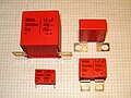
The picture on the right shows a typical metallized polypropylene film capacitor (MKP) of safety class "X2". The many test seals of the various national security organizations are clearly visible in the fourth line of the label.
Snubber capacitors

A snubber is an electrical circuit used to neutralize voltage peaks or transients that occur when switching inductive loads when the current flow is abruptly interrupted. The aim is to achieve better radio interference suppression ( electromagnetic compatibility , EMC), the quenching of sparks on switching contacts (e.g. vehicle ignition coil with mechanical interrupter) and the limitation of the rate of voltage rise on semiconductor switches ( thyristors , GTO thyristors , IGBT , bipolar transistors ) .
Usually a snubber circuit is implemented with a capacitor, possibly in series with a resistor. The capacitor takes over the inductive switch-off current temporarily so that the resulting voltage is limited. However, due to the trend in modern semiconductor technology towards more and more powerful applications, the currents and switching speeds are increasing more and more. More and more newer circuits are built with IGBTs. With the short switching times that can be achieved, extremely high currents have to be switched. This requires a very low-inductance circuit structure.
Both requirements, a low-induction structure and maximum current carrying capacity can be met with plastic film capacitors. Even if standard versions of metallized plastic film capacitors are sufficient for smaller switching capacities, the demands on the film capacitors also increase with increasing switching capacity. The so-called “snubber capacitors” were developed from this motivation. The most important criteria for selecting such a capacitor are low self-inductance, low ESR or low loss factor and high pulse load capacity. These requirements are met by constructive measures in the condenser. A reduction in self-inductance can be achieved through elongated designs with narrower electrodes. By metallizing the electrodes or foils on both sides, the internal ohmic losses can be reduced and the current carrying capacity can be increased. To reduce the inductance and to increase the current-carrying capacity, special connections made of sheet metal are often offered, which are suitable for the screw connections and connection spacings of the semiconductor switches.
Another picture of a snubber capacitor is shown in the “ Types of construction ” section.
Heavy current capacitors
- Types of power film capacitors

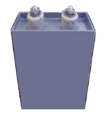


Power capacitors or power capacitors are used in power engineering . They are constructed in such a way that they can withstand high reactive power or high- energy pulses. As a result, power capacitors are usually larger than other capacitors and must be partially cooled (water cooling).
As the size of a capacitor increases, so does the number of possible defects in its internal structure. Due to the self-healing process that cleans up internal defects in metallized film capacitors, components with large dimensions and high reliability can also be produced with this type of construction. Because of the high current load, however, the lowest ohmic losses are required. The dielectric losses must also be low in order to limit the heating inside large volumes. Capacitors with metallized polypropylene films meet these requirements best of all types of film. Depending on the application, metal foil capacitors , metal paper capacitors and completely different designs are also used, see also power capacitors .
Applications

In the power grid large film capacitors for improving the power factor ( power factor correction required). This is you will be on site, e.g. B. in gas discharge lamps with conventional ballast chokes, or used separately in special large systems for reactive power compensation of the low-voltage network, which is often inductive due to motors, chokes and transformers.

Foil capacitors are used to extinguish or attenuate voltage peaks that arise when power semiconductors (e.g. thyristor , triac or IGBT ) are switched off due to the so-called carrier jam effect. These damping capacitors, also called commutation capacitors or snubber capacitors, are often connected in series with a resistor in parallel to semiconductor components. The main property of such capacitors is a very high peak current carrying capacity with high dielectric strength.
Film capacitors can be used in power applications up to the MHz range before their natural resonance sets in. For this purpose, smaller capacitors are expediently connected in parallel or extremely low-inductance designs, often with water cooling, are implemented. Applications include a. inductive heating (tank circuit).
Heavy-current capacitors made of foil are used as surge or pulse capacitors. They are used to receive or deliver a strong, short, but high-energy current surge. Impulse or pulse capacitors are required in research and technology for generating strong magnetic fields , in plasma research and nuclear fusion , for generating high- energy flashes of light or X-ray, in cable fault location devices and in pulse welding machines.
Large film capacitors are also used as backup or DC intermediate circuit capacitors as an alternative to electrolytic capacitors. They smooth the rectified alternating current, filter or screen the alternating currents that flow in the intermediate circuit against ground and deliver periodic peak currents. Examples are frequency converters , actuators and uninterruptible power supplies .
Safety rules for high-voltage film capacitors
High-voltage capacitors and power capacitors are transported and traded short-circuited because of dielectric absorption. Polyester film capacitors in particular have this effect, which causes them to recharge a little after short-circuiting or discharging. See also power capacitor # safety rules .
standardization
The tests and requirements that film capacitors must meet for their approval are set out in the following general specifications.
| standard | Capacitor family |
|---|---|
| IEC 60384-2 | Metallized polyester film capacitors for DC voltage applications |
| IEC 60384-11 | Metal foil-covered polyester foil capacitors for DC voltage applications |
| IEC 60384-13 | Metal foil-covered polypropylene foil capacitors for DC voltage applications |
| IEC 60384-16 | Metallized polypropylene film capacitors for DC voltage applications |
| IEC 60384-17 | Metallized polypropylene film capacitors for alternating voltage and pulse applications |
| IEC 60384-19 | Surface-mountable metallized polyester film capacitors for DC voltage applications |
| IEC 60384-20 | Surface-mountable, metallized polyphenylene sulfide film capacitors for DC voltage applications |
| IEC 60384-23 | Surface mount metallized polyethylene naphthalate film capacitors for DC voltage applications |
In Germany these standards are published as part of the DIN EN 60384 series of standards .
Plastic film capacitors, which are used specifically as safety capacitors (radio interference suppression capacitors), are standardized in accordance with IEC 60384-14. However, since paper capacitors are also used for these purposes, this standard cannot give a clear definition of a film material.
Standard designations
At the beginning of the development of plastic film capacitors, attempts were made to standardize the names of the different capacitor series. The result was DIN 41379, which prescribed an abbreviation for the two versions "metallized" and "with metal coverings" for each material.
The then valid standard stipulated the following abbreviations for the film types known at the time:
| dielectric | Chemical short name |
Abbreviation according to DIN 41379 | |
|---|---|---|---|
| Film capacitor with metal coverings |
Metallized film capacitor |
||
| paper | (P) | - | (MP) |
| Polyethylene terephthalate, polyester | PET | (F) KT | MKT; MKS |
| Polyethylene naphthalate | PEN | (F) KN | MKN |
| Polyphenylene sulfide | PPS | (F) KI | MKI |
| Polypropylene | PP | (F) KP | MKP |
| Polytetrafluoroethylene | PTFE | - | - |
| Polystyrene | PS | KS | |
| Polycarbonate | Pc | (F) KC | MKC |
These abbreviations were largely adopted by the major manufacturers of the time, even the Dutch Valvo / Philips (today BCc / Vishay) adopted the suggestions of the German standard. With the relocation of the mass business of passive components, to which the plastic film capacitors belong, to the Far East from the mid-1970s, many of the new manufacturers defined their own short names for their film capacitor series that differed from the standard.
DIN 41379 has since been withdrawn as part of international harmonization. The standard abbreviations of that time are only used by a few but important manufacturers, including WIMA (with a few exceptions) and BCc / Vishay.
Important parameters
Equivalent circuit diagram

The electrical characteristics of capacitors are harmonized in the technical application in the international area by the framework specification IEC 60384-1, which appeared in Germany as DIN EN 60384-1 (VDE 0565-1) in March 2007. They are described by an idealized series equivalent circuit diagram of a capacitor, in this case a plastic film capacitor.
In the adjacent figure are:
- C , the capacitance of the capacitor,
- R isol , the insulation resistance of the dielectric,
- R ESR , the equivalent series resistance, summarizes the ohmic losses of the component. This effective resistance is generally only called ESR (Equivalent Series Resistance),
- L ESL , the equivalent series inductance, it summarizes the inductance of the component, it is generally only called ESL (Equivalent Series Inductivity L ).
Impedance Z and effective resistance ESR

Analogous to Ohm's law , where the quotient of direct voltage U DC and direct current I DC is equal to a resistance R , the quotient of alternating voltage U AC and alternating current I AC is :

Called alternating current resistance or impedance . It is the amount of the complex impedance of the capacitor at the selected measuring frequency. (In the data sheets of capacitors only the impedance, i.e. the amount of the impedance, is given).


If the series equivalent values of a capacitor are known, then the impedance can also be calculated using these values. It is then the sum of the geometric (complex) addition of the active and reactive resistors, ie, the equivalent series resistance ESR and the inductive reactance X L minus the capacitive reactance X C . The two reactances have the following relationships with the angular frequency ω :

which results in the following equation for the impedance :

(For the derivation of the sign convention used, see under Impedance ).
In the special case of resonance, in which the capacitive and inductive reactance are the same size ( X C = X L ), the impedance is equal to the ESR of the capacitor, the value in which all ohmic losses of the capacitor are combined.
Loss factor tan δ
In the case of plastic film capacitors, the loss factor tan δ is specified in the data sheets instead of the ESR . The loss factor results from the tangent of the phase angle between the capacitive reactance X C minus the inductive reactance X L and ESR . Neglecting the inductance ESL , the loss factor can be calculated as:

Special features of the characteristics of plastic film capacitors
Capacity and capacity tolerance
The capacitance of a plastic film capacitor depends on the frequency. It is measured at a frequency of 1 kHz. The measured value must lie within the specified tolerance range around the nominal value of the capacitance. The deliverable nominal capacitance values, which are graded according to the standardized E series , and the preferred tolerances are linked to one another:
- Nominal capacitance values according to E96, associated tolerance ± 1%, code letter "F"
- Nominal capacitance values according to E48, associated tolerance ± 2%, code letter "G"
- Nominal capacity values according to E24, associated tolerance ± 5%, code letter "J"
- Nominal capacitance values according to E12, associated tolerance ± 10%, code letter "K"
- Nominal capacitance values according to E6, associated tolerance ± 20%, code letter "M"
In addition, film capacitors are also used in other tolerances, e.g. B. 1.5%, 2.5% etc. delivered.
The required capacity tolerance is determined by the respective application. For frequency-determining applications such as resonant circuits, very precise capacitance values that are specified with narrow tolerances are required. In contrast, for general applications such as B. for filter or coupling circuits from larger tolerance ranges.
Frequency and temperature behavior of the capacitance
The different film materials show temperature and frequency-dependent deviations in their characteristic values. The following images show typical frequency and temperature behavior of the capacitance of the different film materials.

Dielectric strength

The dielectric strength of plastic film capacitors is specified, the term " nominal voltage U R " in the new editions of the standards now " Rated voltage U R " called. This means the DC voltage that may be applied continuously in the nominal temperature range up to the upper nominal temperature (rated temperature).
The permissible operating voltage of plastic film capacitors decreases with rising temperature, because the dielectric strength of the film material used decreases with rising temperature. The following figure shows the required voltage load reduction ( derating ) if a capacitor is to be operated above its upper nominal temperature in the range of the so-called "category temperature". The values in this picture have been taken from the corresponding DIN-IEC standards (see respective standard point 2.2.4 "Category voltage"). The derating factors shown apply both to direct voltage and, if applicable, to alternating voltage. Individual manufacturers can have derating curves for their capacitors that deviate from these curves ; for example, certain polyester film capacitors from the manufacturer WIMA allow temperatures of up to 150 ° C with a corresponding load reduction.
Superimposed alternating voltage
The sum of a DC voltage applied to the capacitor and the peak value of a superimposed AC voltage must not exceed the nominal voltage specified for the capacitor. The permissible peak value of the superimposed alternating voltage is frequency-dependent.
Regardless of the type of film, the applicable standards stipulate the following conditions:
| Frequency of the superimposed alternating voltage | Share of the max. Peak value of a superimposed alternating voltage at the nominal voltage |
|---|---|
| 50 Hz | 20% |
| 100 Hz | 15% |
| 1 kHz | 3% |
| 10 kHz | 1 % |
AC voltage or AC current carrying capacity

An alternating voltage or an alternating voltage superimposed on a direct voltage causes charging and discharging processes in the film capacitor. An alternating current flows, which is also known colloquially as ripple current ( ripple current ). It flows through the ESR of the capacitor and leads to ohmic losses that heat the capacitor from the inside out. The internal heat losses are frequency-dependent. The resulting heat is released into the environment. The resulting component temperature depends on the dimensions of the capacitor and other conditions, such as B. Forced cooling. The permissible alternating current load of a plastic film capacitor is generally calculated in such a way that a permissible internal temperature increase of 8 to 10 K is the limit.
In the data sheets of film capacitors, instead of an alternating current, a maximum permissible effective alternating voltage is specified that may be continuously applied to the capacitor within the nominal temperature range. Since the ohmic losses in the capacitor increase with increasing frequency, i.e. the internal heat development increases with constant effective voltage, the voltage must be reduced at higher frequencies in order to maintain the permissible temperature increase.
Exceeding the specified maximum AC voltage can lead to the destruction of the capacitor. This condition leads to the representations of the permissible AC voltage as a function of the frequency, which are so typical for film capacitors.
Impulse resistance, impulse load capacity
An important property of plastic film capacitors is the ability to withstand high voltage or current pulses. Since a pulse is initially defined as a voltage change d u / d t within a period of time, the voltage change results in a current i ( t ) = C · d u / d t . The maximum impulse resistance is thus the capacity of the capacitor to be able to carry the peak current over all its structural parts up to a permissible internal temperature increase.
The permissible pulse load capacity of a plastic film capacitor is generally calculated in such a way that a permissible internal temperature increase of 8 to 10 K is the limit.
The data sheets for film capacitors specify a maximum permissible pulse load that may be applied to the capacitor within the nominal temperature range. Exceeding the specified pulse load can also destroy the capacitor here.
If these data cannot be found in a manufacturer's documentation, this load must be calculated on a case-by-case basis. However, there will not be a generally applicable regulation for calculating the pulse load capacity of film capacitors due to manufacturer-related differences. Therefore, the calculation rule of the manufacturer WIMA can be recommended to explain the generally applicable relationships on this topic.
Impedance (Z)

The impedance of a film capacitor is a measure of the capacitor's ability to conduct or divert alternating currents. The smaller the impedance, the better alternating currents can be forwarded or diverted.
Plastic film capacitors are characterized by very low impedance values and very high resonance frequencies compared to the other capacitor families (ceramic capacitors, electrolytic capacitors).
ESR and loss factor tan δ
All ohmic losses occurring in the capacitor are summarized in the equivalent series resistance ESR. These are the supply and discharge resistance, the contact resistance of the electrode contact, the line resistance of the electrodes and the dielectric losses in the dielectric.
In the case of plastic film capacitors, the loss factor tan δ is specified in the data sheets instead of the ESR . This has to do with the fact that film capacitors were originally mainly used in frequency-determining circles. The reciprocal of the loss factor is z. B. an indicator of quality Q in oscillating circuits . So you can easily determine the quality of the resonant circuit with the loss factor of the capacitor and that of the coil.
The loss factor for film capacitors with metal coatings is, provided the film material is the same, smaller than that of the metallized version. This is due to the lower contact resistance to the electrode foil compared to the metallization.
The loss factor of plastic film capacitors is frequency, temperature and time dependent. While the frequency and temperature dependencies arise from physical laws, the time dependency depends on aging processes such as B. post-shrinking processes and moisture absorption together.
Frequency and temperature behavior of the dissipation factor
The different film materials show temperature and frequency-dependent deviations in their characteristic values. Typical frequency and temperature behavior of the dissipation factor of the different film materials is shown in the following images.

Insulation resistance


A charged capacitor discharges over time through its own insulation resistance R isol . The self-discharge time constant τ isol results from the multiplication of the insulation resistance by the capacitance of the capacitor τ isol = R isol · C. It is a measure of the quality of the dielectric in terms of its insulating capacity and is specified in seconds. In the case of plastic film capacitors, it is generally larger, the more voltage-resistant the insulating film, the dielectric of the capacitor, is. Values between 1000 s and 1,000,000 s are usual. These time constants are always relevant when capacitors are used as a time-determining element (e.g. in timing relays) or for storing a voltage value such as in a sample-and-hold circuit or integrators .
Dielectric absorption, recharge effect
Once capacitors have been charged and are then completely discharged, they can then build up a voltage again without external influence, which can be measured at the connections. This recharge effect is known as dielectric absorption or dielectric relaxation.
While the capacitance of a capacitor is substantially defined by the space charge, it is deviated by atomic restructuring in the molecules of the plastic film to a geometric alignment of the elementary electric dipole in the direction of the prevailing field. This alignment takes place with a much slower time constant than the space charge process of the capacitor and consumes supplied energy. Conversely, this alignment is lost just as slowly with the discharge of a capacitor and returns the energy released in the form of a space charge and thus a voltage on the capacitor. Thus, the dielectric effect always counteracts a change in voltage and thus also causes the partial discharge of a recently charged capacitor. The difference between the time constant of the space charge process and the dipole alignment determines the size of the dielectric absorption and is proportional to each other.
The following table shows the typical values of the dielectric absorption for the film materials used.
| Kind of foil | Dielectric absorption
|
|---|---|
| Polyester (PET) | 0.2 to 0.5% |
| Polypropylene (PP) | 0.01 to 0.1% |
| Polyethylene naphthalate (PEN) | 1.0 to 1.2% |
| Polyphenylene sulfide (PPS) | 0.05 to 0.1% |
Polypropylene film capacitors have the lowest recharging effect of the plastic film capacitors. Therefore, they are ideally suited for analog circuits or also for integrators and sample- and -hold circuits .
Aging
Plastic film capacitors are subject to certain rather small but measurable aging processes. They are based on a slight post-shrinkage of the plastic film, which occurs mainly during the soldering process, but can also be detected during operation at high ambient temperatures or with high current loads, and a small amount of moisture absorption in the capacitor winding under operating conditions in humid climates. The heat load during the soldering process can, for example, change the capacitance value of wired film capacitors by 1 to 5% from the initial value. In the case of SMD designs, the change in the capacitance value due to the soldering process can even be up to 10%.
The loss factor and insulation resistance of film capacitors can also change due to the external influences described above, in particular due to the absorption of moisture in a corresponding climate. Manufacturers can, however, influence the aging processes caused by moisture absorption within certain limits by e.g. B. reduce moisture absorption through denser housing. Under certain circumstances, these measures mean that film capacitors with otherwise the same design can be supplied with different requirement levels.
Labelling
Plastic film capacitors are no longer marked using color coding. If there is enough space, capacitors should be labeled with: nominal capacity, tolerance, nominal voltage, nominal temperature range (climate category), temperature coefficient and stability class, date of manufacture, manufacturer, type designation. Radio interference suppression capacitors must also have the appropriate approval mark.
Capacity, tolerance and date of manufacture can be marked with abbreviations according to EN 60062. Examples of a short description of the nominal capacitance (nanofarad): n47 = 0.47 nF, 4n7 = 4.7 nF, 47n = 47 nF
Applications
The main advantages of metallized plastic film capacitors are very low ohmic losses (ESR) and a small inductance (ESL), combined with a high pulse load capacity compared to capacitors of other capacitor families , which can be increased constructively by using metal foils instead of foil metallization. In the case of the polypropylene film, there is also a slight temperature dependence of the capacity and the loss factor. PP film capacitors thus meet the criteria of class 1 capacitors and are used in oscillators , resonant circuits for higher power, frequency filters, tuning circuits and temperature- stable timing elements . They are also used in high- or low-pass filters with high quality for crossovers for loudspeakers . They are also used in analog-to-digital converters ( sample and hold AD converters ) and in peak voltage detectors.
The high pulse load capacity and the low ohmic losses combined with a stable behavior over a larger temperature range are also the reasons for the use of polypropylene film capacitors for use in tube television sets as synchronous pulse capacitors ( TV S-correction ) and as line return capacitors (English TV fly-back tuning ). For these reasons, polypropylene film capacitors are used in power electronics as damping capacitors (“ snubber ” capacitors), often with special connections designed for high current loads, for spark quenching on IGBT or GTO thyristor switches.
Because of the high pulse load capacity, PP capacitors are also used in pulse applications, e.g. B. in cable fault location devices, in pulse welding machines, in lasers for generating laser flashes or in plasma research and nuclear fusion , for generating high-energy light or X-ray flashes .
In addition, medium-sized polypropylene film capacitors are used in AC applications , e.g. B. used as a phase shifter in fluorescent lamps or as motor operating capacitors .
Polypropylene film capacitors reach very large dimensions as power capacitors for AC applications in systems, where they are used e.g. B. can be used for reactive current compensation and harmonics cancellation .
For simpler applications that do not depend so much on stable parameters in a wide temperature range, such as B. the filter capacitors for screening interference signals or glitches and for noise suppression or for coupling AC signals , cheaper plastic film capacitors are used. In the past, these were polystyrene capacitors (KS), often as “stacked” designs, today they are replaced by polyester film (KT). Thanks to the possibility of producing smaller capacitance values with these plastic film capacitors, which are designed for higher frequencies, higher frequencies or steep impulses can also be blocked with the "Folkos". Folkos are therefore considered to be "particularly fast" and they are often used at the output of power packs, parallel to an electrolytic capacitor with a much larger capacity in order to be able to screen a wide frequency spectrum in cooperation with it.
Plastic film capacitors are also often used in voltage regulators or voltage doubler circuits.
The fact that special plastic film capacitors have self-healing properties and breakdowns do not lead to the destruction of the component makes them suitable as contact protection capacitors also for applications in the field of interference suppression capacitors.
Foil capacitors with foils made of PTFE are used for applications that have to withstand particularly high temperatures. z. B. in military equipment, in geo-probes , in burn-in circuits.
Advantages and disadvantages
Foil capacitors are mostly used for "frequency-stable circuits" when larger capacities are required than can be economically achieved with class 1 ceramic capacitors . Like class 1 ceramic capacitors, they also have the following advantages:
- Small loss factors, high quality .
- Little dependence of the capacity and the dissipation factor on the temperature and the frequency
In the area of "power supply", film capacitors compete with electrolytic capacitors and high-capacity class 2 ceramic capacitors made of ceramics such as X7R, over which they have a number of advantages:
- Electrically stable and low power loss
- Better tolerance to (rare) overvoltage peaks due to self-healing
- High impulse stability
- High ampacity
- No significant aging compared to electrolytic capacitors
- Higher voltage range than electrolytic capacitors
- No microphony in contrast to ceramic capacitors
The two biggest disadvantages of film capacitors compared to electrolytic capacitors and high-capacity ceramic capacitors are:
- Relatively large design
- Limited range of inexpensive SMD designs
- Self-ignition in the event of overload (AC voltage) or improper use possible
swell
- IEC Hughes: Electronic Engineer's Reference Book. Heywood & Company LTD, London 1958
- Dieter Nührmann: Workbook Electronics: the large workbook with design data , tables and basic circuits for all areas of applied and practical electronics. Franzis-Verlag, Munich 1981, ISBN 3-7723-6543-4 .
- Tadeusz Adamowicz: Handbook of Electronics: a detailed presentation for engineers in research, development and Practice. Franzis-Verlag, Munich 1979, ISBN 3-7723-6251-6 .
- Kurt Leucht: Capacitors for electronics engineers: a detailed presentation of the capacitors and their characteristics, designs and special properties; Application examples u. Identification systems. Franzis, Munich 1981, ISBN 3-7723-1491-0 .
- Hans Loth: Film Capacitors: Types, Technologies and Applications. Verlag Moderne Industrie, Landsberg / Lech 1990, ISBN 3-478-93046-4 .
- Otto Zinke , Hans Seither: Resistors, capacitors, coils and their materials. Springer, Berlin / Heidelberg / New York 1982, ISBN 3-540-11334-7 .
- DIN EN 60384-1, −2, -11, −13, -14, −16, -17, −19, -23, Beuth-Verlag
- Petrick, Nögel, Helwig: Modern capacitor technologies. Roederstein 22–79, Capacitor and Resistance Technology
- G. Hunger: Application criteria and design features of modern plastic film capacitors. elektronik journal 8, 1981
- W. Westermann: Wrapping or layering technology, that is the question here. Electronics 5/6, 1988
- R. Hecker: Mini is in, ways of miniaturizing plastic film capacitors. Electronics 13, 1991
- W. Westermann: The film capacitor, a "discontinued model"? WIMA reprint 09.2005
- P. Olbrich: Thicker Layer on Thinner Substrates. Passive Component Industry, Nov / Dec 2005
- CapSite 2015 - Introduction to Capacitors , release 3.9, [7] (English)
- Dieter Nührmann: The complete workbook electronics volume 1 & 2, Franzis-Verlag, 2002, ISBN 3772365264 .
- CAPACITORS MV AND HV POWER FACTOR CORRECTION SYSTEMS AND FILTERS Ducati
- Capacitor Catalogs . Electronicon
- TDK Epcos
- Capacitors Product List . General Electric (GE)
Web links
- Self-made film capacitors: Make your own High-Voltage Capacitor , Tony van Roon (English)
- Introduction to Capacitors: [8]
Search lists from manufacturers of passive components, including film capacitors
- Sherlab, http://www.sherlab.com/
Manufacturers and Products
In addition to the manufacturers named under the subtitle “Market” in this article, there are many who specialize in film capacitors. The following table gives an overview of the product ranges of global manufacturers of plastic film capacitors (without power or high-voltage capacitors, as of July 2008):
| Manufacturer | Available finishes | ||||
|---|---|---|---|---|---|
| SMD condensation catalysts |
Standard condensation catalysts |
Suppressor condensation catalysts |
, Snubber pulse condensation catalysts |
PTFE / PC and- special film condensation catalysts |
|
| AVX / Kyocera Ltd. | X | X | - | - | - |
| American Capacitor Corp. | - | X | - | X | X |
| Bishop Electronics | - | X | - | - | - |
| Capacitor Industries | - | - | X | - | - |
| Cornell-Dubillier | X | X | X | X | - |
| Custom Electronics, Inc. | - | - | - | X | X |
| Dearborne | - | X | - | X | X |
| DEKI Electronics | - | X | X | X | - |
| Epcos | - | X | X | X | - |
| EFC [Electronic Film Capacitors] | - | X | X | X | X |
| Electrocube | - | X | X | X | X |
| Electronic Concepts Inc. | - | X | - | X | X |
| Eurofarad | - | X | X | X | X |
| Faratronic | X | X | X | X | X |
| FTCAP | - | X | X | X | X |
| Hitachi AIC Inc. | X | X | - | X | - |
| Hitano Enterprise Corp. | - | X | X | - | - |
| Illinois Capacitor | - | X | X | X | - |
| ITW pactron | X | X | X | X | - |
| Jianghai | - | X | X | X | X |
| KEMET Corporation , including Arcotronics, Evox-Rifa | X | X | X | X | - |
| Meritek Electronics Corp. | - | X | X | - | - |
| MFD capacitors | - | X | - | X | X |
| NIC | X | X | X | - | - |
| Nichicon | - | X | - | - | - |
| Nippon ChemiCon | - | X | - | X | - |
| Panasonic | X | X | X | X | - |
| Richey Capacitor Inc. | - | X | X | - | - |
| Rubycon | - | X | - | X | - |
| Solen Electronique Inc. | - | X | - | X | X |
| Suntan Technology Company Limited | X | X | X | - | - |
| Surge Components | - | X | X | - | - |
| Tecate Group | - | X | X | X | - |
| TSC | - | X | - | - | X |
| Vishay Intertechnology Inc. incl. Roederstein, BCc | - | X | X | X | - |
| Würth Elektronik GmbH & Co. KG | - | X | X | - | - |
| WIMA | X | X | X | X | - |
Individual evidence
- ↑ Archive link ( Memento of the original from September 29, 2013 in the Internet Archive ) Info: The archive link was inserted automatically and has not yet been checked. Please check the original and archive link according to the instructions and then remove this notice. (PDF; 261 kB) P. Winsor, E. Lobo, Aerovox, Corp., New Polymer Dielectric For High Energy Density Film Capacitors
- ↑ P. Olbrich, Applied Films GmbH & Co. KG, Advanced Coating Technology for Film Capacitor Applications, CARTS USA 2005 Archive link ( Memento of the original from September 29, 2013 in the Internet Archive ) Info: The archive link was inserted automatically and has not yet been checked. Please check the original and archive link according to the instructions and then remove this notice. (PDF; 583 kB)
- ↑ P. Olbrich, Innovative Solutions in Film Capacitor Vacuum Coating for advanced automotive Applications, CARTS Asia 2006 Archive link ( Memento of the original from September 29, 2013 in the Internet Archive ) Info: The archive link was inserted automatically and has not yet been checked. Please check the original and archive link according to the instructions and then remove this notice. (PDF; 783 kB)
- ↑ WIMA, Metallized Structure ( Memento of the original from August 14, 2012 in the Internet Archive ) Info: The archive link was automatically inserted and not yet checked. Please check the original and archive link according to the instructions and then remove this notice.
- ↑ Archive link ( memento of the original dated November 26, 2016 in the Internet Archive ) Info: The archive link was inserted automatically and has not yet been checked. Please check the original and archive link according to the instructions and then remove this notice. Radio interference suppression capacitors of class X1 made of metallized polypropylene (PP) with internal series connection ...
- ↑ Y. Vuillermet ao, Optimizing of Low-Voltage Metallized Film Capacitor Geometry, IEEE TRANSACTIONS ON MAGNETICS, April 4, 2007, [1] (PDF; 493 kB)
- ↑ [2] Technical trend of power film capacitors for industrial applications, Rubycon.
- ↑ http://techdoc.kvindesland.no/radio/passivecomp/20061223155212518.pdf
- ↑ Paumanok Publications Inc. , PCInewsletterOct2007cmp
- ↑ Evox Rifa
- ^ Arcotronics Nissei Group
- ↑ Panasonic
- ↑ Hitachi Passive Components Europe
- ↑ Fischer & Tausche
- ↑ ELECTRONICON
- ↑ FRAKO
- ↑ Electronic components Görlitz - Electel ( Memento of the original from September 29, 2007 in the Internet Archive ) Info: The archive link was inserted automatically and has not yet been checked. Please check the original and archive link according to the instructions and then remove this notice.
- ↑ WIMA, comparison of the typical properties of metallized plastic film capacitors with other capacitor technologies ( memento of the original from March 20, 2013 in the Internet Archive ) Info: The archive link was automatically inserted and not yet checked. Please check the original and archive link according to the instructions and then remove this notice.
- ↑ a b Film Capacitors, TDK Epcos, General technical information (PDF; 1.4 MB)
- ↑ AVX, Dielectric Comparison Chart (PDF; 161 kB)
- ↑ Holystone, Capacitor Dielectric Comparison, Technical Note 3 (PDF; 64 kB)
- ↑ Andritz AG, BOPP, Biaxially oriented polypropylene [3] ( page no longer available , search in web archives ) Info: The link was automatically marked as defective. Please check the link according to the instructions and then remove this notice.
- ^ Trade name of the DuPont company
- ↑ Werner Bächtold: Linear elements of high frequency technology , lecture at the department for electrical engineering of the Swiss Federal Institute of Technology in Zurich; Hochschulverlag AG, 1998 - 171 pages; Page 19
- ^ Solen Electronique Inc.
- ↑ EFC Wesco
- ^ Electrocube
- ↑ Exxelia group ( Memento of the original from January 9, 2016 in the Internet Archive ) Info: The archive link was inserted automatically and has not yet been checked. Please check the original and archive link according to the instructions and then remove this notice.
- ↑ TSC Electronics Inc.
- ↑ Nylon, material data sheet, DuPont (PDF; 500 kB)
- ↑ [4] YEC, China
- ↑ S. Zhang, B. Zellers, D. Anderson, P. Rehrig, X. Zhou, D. Kushner, R. Russo, High Dielectric Constant Polymer Film Capacitors [5]
- ↑ P. Winsor, E. Lobo, Aerovox, Corp, New Polymer Dielectric For High Energy Density Film Capacitors Archive link ( Memento of the original from September 29, 2013 in the Internet Archive ) Info: The archive link was inserted automatically and has not yet been checked. Please check the original and archive link according to the instructions and then remove this notice. (PDF; 261 kB)
- ↑ BASF, Ultrason brochure [6] (PDF; 6.4 MB)
- ↑ Vectran, General Properties ( Memento of the original from February 5, 2012 in the Internet Archive ) Info: The archive link was automatically inserted and not yet checked. Please check the original and archive link according to the instructions and then remove this notice.
- ↑ http://www.celem.com/Page.aspx?id=11&hmenu=12 from Celem
- ↑ Calculation rule for the impulse load capacity on the website of the manufacturer WIMA ( Memento of the original of September 27, 2007 in the Internet Archive ) Info: The archive link was inserted automatically and not yet checked. Please check the original and archive link according to the instructions and then remove this notice.
- ↑ WIMA, The film capacitor a "discontinued model"? ( Memento of the original from August 15, 2011 in the Internet Archive ) Info: The archive link was inserted automatically and has not yet been checked. Please check the original and archive link according to the instructions and then remove this notice.
- ↑ Overview of the main applications of plastic film capacitors with general switching examples ( Memento of the original from September 27, 2007 in the Internet Archive ) Info: The archive link was automatically inserted and not yet checked. Please check the original and archive link according to the instructions and then remove this notice. from Wima.
- ↑ Web presence of the manufacturer AVX / Kyocera Ltd.
- ↑ Website of the manufacturer American Capacitor Corp.
- ↑ Web presence of the manufacturer Bishop Electronics ( Memento of the original from September 10, 2011 in the Internet Archive ) Info: The archive link has been inserted automatically and has not yet been checked. Please check the original and archive link according to the instructions and then remove this notice.
- ↑ Web presence of the manufacturer Capacitor Industries
- ^ Website of the manufacturer Cornell-Dubillier
- ↑ Website of the manufacturer Custom Electronics, Inc.
- ^ Website of the manufacturer Dearborne
- ↑ the manufacturer's website DEKI
- ↑ Web presence of the manufacturer TDK Epcos
- ^ Website of the manufacturer Electronic Film Capacitors
- ^ Website of the manufacturer Electrocube
- ↑ Website of the manufacturer Electronic Concepts Inc
- ↑ Web presence of the manufacturer Eurofarad ( Memento of the original from June 20, 2009 in the Internet Archive ) Info: The archive link was inserted automatically and has not yet been checked. Please check the original and archive link according to the instructions and then remove this notice.
- ↑ the manufacturer's website Faratronic
- ↑ the manufacturer's website FTCAP
- ↑ Website of the manufacturer Hitachi AIC Inc.
- ↑ Website of the manufacturer Hitano Enterprise Corp.
- ^ Website of the manufacturer Illinois Capacitor
- ↑ website of the manufacturer ITW PAKTRON
- ↑ website of the manufacturer Jianghai Europe
- ↑ Website of the manufacturer Kemet
- ↑ Web presence of the manufacturer Meritek Electronics Corp.
- ↑ Website of the manufacturer MFD Capacitors
- ^ Website of the manufacturer NIC
- ↑ website of the manufacturer Nichicon
- ↑ website of the manufacturer Nippon Chemi-Con
- ↑ Website of the manufacturer Panasonic ( Memento of the original dated February 9, 2012 in the Internet Archive ) Info: The archive link was inserted automatically and has not yet been checked. Please check the original and archive link according to the instructions and then remove this notice.
- ↑ Web presence of the manufacturer Richey Capacitor Inc.
- ↑ Web presence of the manufacturer Rubycon
- ↑ Online catalog of the manufacturer Solen Electronique Inc.
- ^ Website of the manufacturer Suntan Technology Company Limited
- ^ Website of the manufacturer Surge Components
- ↑ Web presence of the manufacturer Tecate Group ( Memento of the original from 23 August 2012 in the Internet Archive ) Info: The archive link was inserted automatically and has not yet been checked. Please check the original and archive link according to the instructions and then remove this notice.
- ↑ Web presence of the manufacturer TSC
- ^ Website of the manufacturer Vishay
- ↑ Web presence of the manufacturer Würth Elektronik online catalog - film capacitors
- ↑ Web presence of the manufacturer Wima