
Tilting technique
.jpg)

Tilting technology , also track curve-dependent car body control (abbreviation Neitech , GSt ), is a technique in which the car bodies of a train can be tilted towards the inside of the curve with respect to their chassis. This reduces the perceived lateral acceleration.
The tilting technology allows faster driving through curves, with higher lateral acceleration than otherwise permitted, which is referred to as “ driving at a fast curve”. If the lateral acceleration is not increased ( control speed ), the system can be used to make cornering more pleasant ("comfort tendency").
Effects

The tilting technology enables trains to lean into the curve with an inclination of up to 8.6 °. This shifts the train's center of gravity to the inside of the curve. This reduces the overturning moment to the outside of the curve, so you can drive through curves at up to 30% higher speed. Furthermore, the comfort of the passengers is less affected by increased lateral acceleration ( centrifugal force ).
The tilting technology shortens travel times on winding routes. For example, the use of class 612 tilting technology trains on the Chemnitz - Leipzig route has reduced travel time from 59 minutes to 52 minutes. In addition, this technology makes it possible to do without expensive new routes, as higher speeds are possible on the old routes.
example
The following table gives an example of the mathematical increase in speed through the use of the tilting technique.

With


| Arc radius | speed | speed | speed |
|---|---|---|---|
| conventional | with 4.3 ° tilt technology | with 8.6 ° tilt technology | |
| R / meter | v perm / (km / h) | v perm / (km / h) | v perm / (km / h) |
| 200 | 60 | 80 | 90 |
| 500 | 100 | 120 | 140 |
| 800 | 130 | 160 | 180 |
| 1100 | 160 | 180 | 210 |
| 1400 | 180 | 210 | 240 |
| 1700 | 200 | 230 | 260 |
| 2000 | 210 | 250 | 280 |
Note: The table values are rounded to the nearest 10 km / h.
Side effects
In connection with the introduction of system, there were many discussions about whether and to what extent the acting during tilt operation on the passengers strokes nausea and motion sickness , and motion sickness or SMS (symptoms of motion sickness) called, can trigger. The information on the frequency of such observations varies widely, with incidence rates of up to 30 percent being reported. The extent of such side effects depends, on the one hand, on the mutual coordination of driving dynamics and route characteristics (e.g. length of transition arcs, frequency of curves) and, on the other hand, on the personal vulnerability of passengers and their seating position in the vehicle. For example, a 12 percent higher incidence and three times as high an incidence of symptoms were observed in women than in men. With a reduction in the proportion of the compensated lateral acceleration in the total (unbalanced) lateral acceleration from 70 to 55 percent, a study showed a reduction in the incidence of motion sickness by 25 to 40 percent. An incidence two to three times higher in women than in men was observed.
Vulnerable people are advised to sit facing the direction of travel and not at the window.
technology
Vehicles with active tilting technology are (as of 2019) u. a. offered by Alstom ( Pendolino family) and CAF (SIBI system).
Positioning systems
A distinction is made between passive and active tilting technology:
- With passive tilting technology , the car bodies are suspended above their center of gravity on raised extensions of the chassis girder. Because of the centrifugal force , they swing outward in the lower area and inward in the upper area. The vibrations are calmed down by damping elements. The tilt angle is limited to 3.5 °. As a result, the gain in speed when cornering is also significantly lower than with active systems. Often the passive tilting technology, as with the Spanish Talgo train, only serves to improve comfort. In Switzerland, however, a passive tilting technique called roll compensation is to be used in the future to shorten travel times in order to be able to maintain ITF node times.
- With active tilting technology, hydraulic actuating cylinders ( hydraulic cylinders ) or an electric actuator (electric motor with high-reduction gear and spindle drive that converts the rotational movement of the electric motor into a linear movement) ensure that the car bodies deflect. The tilt angle can be up to 8.6 °. The classic solution with hydraulics harbors the always latent environmental hazard caused by the typical leaks in the hydraulic cylinders.
- There are mixed forms of the positioning systems z. B. in Japan, for example passive tilt systems in which the inclination is actively initiated and withdrawn.
Talgo Pendular car set with passive tilting technology
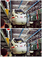
Comparison between inclined (above) and inclined (below) car body of the ICE T (demonstration while standing)
Demonstration of the tilting technology of an SBB RABDe 500 in the stand.


Sensory concepts
In the case of active systems, a distinction is also made between different system configurations of the control and the associated sensors:
- In the inertial system , at least the lateral acceleration is measured using inertial sensors and the inclination is adjusted accordingly. Almost all current developments use inertial systems.
- With the complete system , all six degrees of freedom (3 accelerations, braking, pitching, swinging and three angular speeds yaw, pitching, tilting) are measured by sensors and the inclination is adjusted accordingly. After measurement and driving tests, this solution has hardly been used so far, since from the point of view of machine technology the measurement effort is considered too high compared to the improvement in comfort achieved. In fact, the cost of measuring technology based on modern MEMS sensors does not mean any price difference.
- In the case of an incomplete system , not all six degrees of freedom (for example 3 accelerations and two angular speeds) are measured by sensors in three dimensions and the inclination is set accordingly. This system is inferior to the complete system in terms of measurement errors and causes non-dangerous, but irritating control errors when switching to points quickly.
- In knowledge-based systems , the necessary inclination to be expected is taken from a database as a function of the current train position.
An exclusively knowledge-based system is not robust against interference without sensors and is therefore hardly suitable for comfort. " SIBI " - the tilting technology from the Spanish manufacturer CAF - uses prefabricated maps in conjunction with GPS receivers and odometers and can therefore do without balises .
There are different arrangements of the measuring units in the vehicles: It is rather seldom that measurements are taken in the car body, where comfort is to be created, this solution is slow to deal with the disturbances, but comfortable. Most of the time, measurements are taken in the bogie where the disturbances are introduced from the track bed; this solution is quick to deal with the disturbances. Measuring is only particularly economical in the first vehicle, as the malfunctions in the following vehicles can only be estimated.
Consequences for the floor plan
In order for the trains to fit into the clearance profile of old building routes even with active tilting technology , the side walls are usually set at an angle. The interior space is narrower in the upper area than in a rigid train.
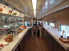
Dining car in the X2000
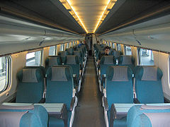
Second class in the ETR 470


Bogies and suspension are more complicated than with conventional railcars. Heavy components in the inclined part of the vehicle (transformers or fuel tanks, diesel engines and generators) should also be mounted as close to the tilt axis as possible in order to keep the moment of inertia and thus the effort required for the tilting process as low as possible; they are therefore usually placed under the floor. Both together then become a structural problem if the vehicle is also to be designed in a low-floor design.
Tilting technology and traction concept

Although the tilting technology could in principle also be used for trains hauled by locomotives, provided that the permissible axle loads are observed, tilting trains are usually designed as multiple units . If the drive is concentrated in power cars, then only the intermediate cars have to be equipped with tilting technology, since the process only improves the driving comfort for the passengers (and not the safety of the lane guidance).
In the case of electric multiple units with distributed drive, the pantographs mounted on the roof of the individual multiple units must not tilt so that contact with the contact wire is maintained. This can be achieved in the following ways:
- The vehicle on which the pantograph is mounted does not tilt. The solution was implemented, for example, in the power car of the X2000 .
- The pantograph sits on a non-sloping frame that rests directly on the bogie, such. B. with the FS ETR 470
- The pantograph sits on a subframe on the roof of the vehicle and is moved by its own actuator against the inclination of the car body, such. B. ICE T and SBB RABDe 500 .
Operational characteristics
Operationally, journeys with a tendency towards comfort differ only slightly from journeys with rigid trains; they lead to increased expenditure in the construction and maintenance of the more complex trains.
The introduction of tilting technology to accelerate rail traffic places complex demands on the mutual coordination of infrastructure and rolling stock. In this case, the effort on the part of the infrastructure also increases.
The signaling technology in particular must be designed for the higher speeds. In Germany, in addition to normal train control (PZB), speed monitoring tilting technology (GNT) is used, which releases the increased speed when it can be driven safely. The security of level crossings must be changed so that the barriers are closed in good time, even if the train is faster.
For the superstructure, it does not matter whether the car is upright or inclined through the curves, given the same speed and mass. However, increased cornering speeds lead to higher wear on the track and wheel rim. In order to be able to use the tilting technique with a gentle change of inclination, curves must contain transition arcs. Sudden changes in curvature, such as those that occur especially in switch areas , must not be driven on at a bend speed.
In Germany, tilting technology is only approved for arc-fast driving up to 160 km / h. In the high-speed range, only the comfort slope is used; new high-speed routes are not designed for driving at high speeds. On the other hand, the re-routing of old routes can be omitted after using the tilting technique.
In the European train control system ETCS , the following train rows are intended for tilting trains:
| designation | Train type | Cant deficit |
|---|---|---|
| TILT 1 | Tilting train | 165 mm |
| TILT 2 | Tilting train | 180 mm |
| TILT 3 | Tilting train | 210 mm |
| TILT 4 | Tilting train | 225 mm |
| TILT 5 | Tilting train | 245 mm |
| TILT 6 | Tilting train | 275 mm |
| TILT 7 | Tilting train | 300 mm |
economics
The use of tilting technology leads to higher procurement and maintenance costs for vehicles, higher demands on the maintenance of the infrastructure, costs for selective changes to the infrastructure (radii, elevations, switch-on sections of level crossings, etc.) as well as the necessary safety equipment (e.g. GNT ). The costs for necessary adjustments to the route are roughly quoted by Deutsche Bahn as less than 100,000 euros per route kilometer.
According to information provided by Deutsche Bahn in 2007, the limitation of the axle load of tilting technology trains to 16 t means that no higher load on the infrastructure due to the use of tilting technology can be determined. Additional maintenance costs were incurred for the annual review of the balises as well as costs due to the earlier reaching of limit values.
Comparison with an undeveloped route
The permissible speed in arcs can be increased by up to 40 km / h by tilting technology, starting from a conventional speed of up to 120 km / h; Under very favorable conditions, travel time savings of up to 20 percent can be achieved, but in many cases only up to around 10 percent. Travel time gains (regardless of how they are achieved) lead to two possible economic advantages:
- Productivity increases because a vehicle (including its crew) can provide a higher transport performance in a given time. If a vehicle needs 35 minutes for a route on a line with hourly intervals, a second vehicle is necessary to keep the hourly intervals. In addition, both vehicles have a turning time of 25 minutes at the terminal stations. If this route is accelerated by 10 minutes by tilting technology, a single vehicle on this line can guarantee an hourly cycle and only has a turning time of 5 minutes at the terminal stations.
- If you have to brake less before turning and accelerate again afterwards, energy is saved and wear and tear is reduced.
- Many travelers perceive faster connections as more attractive; both the number of customers and their willingness to pay can increase.
These advantages only come into play if the acceleration can actually be used and does not lead to longer standstill and transfer times. Saving vehicles through shorter turning times is often problematic, as delays sometimes have to be carried over to subsequent journeys and, if the turning times are particularly short, they cannot be made up again by the end of the business day. This can reduce the general punctuality and thus also the attractiveness for the passengers.
The advantages are also offset by the investment costs for more expensive trains (and possibly special track equipment) as well as higher maintenance costs for vehicles and (depending on the design) the track.
Comparison with re-routing
The re-routing of a route usually leads to much higher costs than the equipment for tilting technology. In addition, re-routing is usually not possible in built-up areas. The savings in construction costs are generally offset by the higher procurement and maintenance costs for the wagons. In addition, rerouting is a one-time cost (experience shows that railway lines from the 19th century are still used today) whereas the purchase of rolling stock is a recurring cost.
Comparison with electrification
In principle, electrification and expansion for tilting technology can be carried out independently of one another. In some cases, however, the clearance profile limits such extensions. Compared to diesel-powered trains, electric trains have better acceleration under otherwise identical conditions, which is particularly advantageous on routes with frequent stops (e.g. S-Bahn). In addition, the fuel costs fall considerably in some cases. In Germany, electric railcars are rarely equipped for tilting technology, but such models have been in use internationally for years. The pantograph, which must be movable for tilting technology, is particularly problematic.
Examples


Long-distance transport
- Pendolino of Trenitalia (Italy)
- X2000 from SJ (Sweden)
- Numerous Cape Gauge multiple units of the Japanese Railways as well as the latest Shinkansen generation 700N
- ICE T and ICE TD of DB (Germany)
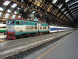
- ETR 470 from Cisalpino AG on the connections Switzerland - Italy
- RABDe 500 ("ICN") of SBB (Switzerland)
- Talgo from generation Talgo pendular (Spain)
- Alaris (Spain)
- Class 680 of the ČD (Czech Republic)
- Alfa Pendular (Portugal)
Local transport
- Diesel multiple units class 610 , class 611 and class 612 of the DB
history
In 1928, Franz Kruckenberg registered a patent for an active hydraulic tilting system with automatic control. The passive tilting technique has already been assumed as prior art in this document.
In 1941 three "Pendulum Coaches" with passive tilting technology appeared on three US railways (Santa Fe, Burlington and Great Northern). The car body was mounted on the bogies at about the level of the lower edge of the window and could swing out in the bends, but without damping. The cars ran until the 1960s, and scheduled operations at Burlington in the 1950s have been photographed.
After the Second World War , tests with tilting technology vehicles were started in Germany, France, Great Britain, Italy, Sweden and Spain. An early prototype was made in France in the 1950s.
Italy
Fiat Ferroviaria made the breakthrough to a functional active hydraulic tilting technology with the prototype Y 0160 , which was built in 1971 and tested until 1975. With the experience gained, FIAT built the ETR 401 in 1975 . The first series trains with the new technology ( ETR 450 ) were not ordered until 1984, despite the high reliability of the test vehicle. They have been used regularly since 1988.
Great Britain
At the end of the 1960s, engineers at the British Rail Research Division began developing the Advanced Passenger Train , which also featured a new type of active tilting technology. The balise-supported monitoring system C-APT was used to transmit the maximum permissible speed with activated arc-fast driving .
Today the West Coast Main Line is equipped with the TASS system, based on Eurobalises , which enables bend-fast travel. On the vehicle side, the system is installed in Class 221 and Class 390 .
Spain
While active tilting technology took many years from readiness for series production to series use, the commercial use of passive tilting technology began in 1980 with the Spanish Talgo Pendular trains.
Active tilting technology has also been in use in the RENFE 594 series since 1997.
France
In France and Switzerland, the active tilting technology on single wagons of the Voiture Grand confort (SNCF) and EW III (SBB) series was further developed. The technology was brought to maturity in Italy and Sweden and used commercially for the first time in the Pendolino trains built by Fiat and in the Swedish SJ X2 .
Germany
Tests carried out in Germany from 1965 onwards with an active pneumatic control based on air suspension failed because the control technology was not yet fully developed. In 1968 a German diesel multiple unit with tilting technology was tested on the Ingolstadt – Treuchtlingen railway line .
In Germany, the first railcar series built for commercial use with tilting technology developed in Germany did not prove themselves. These included the 634 and 614 series diesel multiple units . The vehicles were equipped with the then new air suspension . The inclination in the arches was made by redistributing the air between the springs on the left and right sides of the vehicle. The solution was not sufficiently stable, so that the Deutsche Bundesbahn and the German rail technology industry showed no interest in tilting technology for years. The class 403 express railcar, developed at the same time, was also tested with a track curve-dependent tilting system. The car body could be inclined by up to four degrees in curves; Due to the pantographs being permanently mounted on the roof, only a maximum incline of two degrees was practicable. Since the roll axis was also too low, the driving comfort suffered considerably, which is why the tilting technology was completely deactivated in normal operation.
It was only after the success of the Pendolino trains in Italy and the X2000 in Sweden that interest in this technology reawakened in Germany. In 1987 and 1988, an Italian Pendolino (series ETR 401 ) was twice on the German route network for test drives. Between July 13 and 31, 1987, the train ran on the Moselle route Koblenz - Trier - Dillingen and between Ingolstadt and Treuchtlingen. In 1988 there was a test drive on April 11th with Federal Transport Minister Jürgen Warnke and Bavaria's Transport Minister Anton Jaumann . In 1989, several measurement and demonstration runs with the Spanish Talgo Pendular followed .

At the end of 1989, the Italian Pendolino prototype was presented on a tour from Kaiserslautern via Neustadt to Wörth . On board were, among others, Minister of Economic Affairs Rainer Brüderle and the DB board members Knut Reimers and Hans Wiedemann. Reicherts expected the vehicles to be used as planned in the Saarland from 1991, if the relevant negotiations between the Federal Railroad and the state about financing up to 25 vehicles could be concluded promptly and successfully.
The then Federal Railroad began to consider using tilting technology in German long-distance transport in 1988. The first German Neitech class 610 operated between Nuremberg and Hof in 1992 .
After the success of the 610 series, between 1997 and 2003 over one hundred trains of the 611 and 612 series were procured for fast regional traffic in Baden-Württemberg, Bavaria, Lower Saxony (Harz region), Rhineland-Palatinate, Saxony, Saxony-Anhalt (Harz region) and Thuringia were used. In the 2010s, however, these diesel multiple units were replaced by electrification programs (example Dresden – Hof) and new tenders (example Halle – Goslar – Hanover). The tilting technology also proved to be prone to failure, especially in winter due to icing, and the vehicles were not barrier-free due to the car body inclination. In 2018 and 2019, all vehicles of the 611 series were retired and the 612 series vehicles were only used on some winding mountain routes in the Allgäu, between Nuremberg and Hof and on non-electrified main routes in Thuringia. In Lower Saxony, Saxony-Anhalt, Saxony and Rhineland-Palatinate, operations were completely stopped and some of the remaining vehicles were handed over to standstill management and some were redesigned for use in Baden-Württemberg.
In long-distance traffic, ICE trains with active tilting technology were first used between Stuttgart and Singen, and later between Stuttgart and Zurich, in 1999. Further areas of application for the 70 electric multiple units acquired by 2005 were Munich-Nuremberg-Jena-Leipzig-Berlin, Wiesbaden-Frankfurt-Leipzig-Dresden and Dortmund-Frankfurt-Nuremberg-Passau-Vienna. The trains ran largely reliably until 2008. In October 2008, a crack was discovered on a wheelset on a multiple unit of the second series, which led to the temporary shutdown of the entire vehicle fleet. Until the new development of new axes, the active tilting technology could no longer be used in arc-fast operation due to the increased load on the axes. It was not until 2018, 10 years after the shutdown, that the tilting technology was released again on the Nuremberg – Passau route to reduce travel times.
According to the federal government in 2019, vehicles with tilting technology will no longer be procured in long-distance transport in Germany because the technology is not sustainable and the number of corresponding vehicle manufacturers is declining. The Bavarian Railway Company , however, intends to use new tilting multiple units in the long term.
Switzerland
Four different types of trains are or were on the move in Switzerland with tilting technology.
The first tilting technology trains were the ETR 470 , which came from Milan via the Lötschberg or Gotthard to Switzerland. Some of these drove as far as Stuttgart. They drove from 1996 to the end of 2009 on behalf of Cisalpino . Since then, they have been operating on behalf of the FS and SBB .
Since 1999, SBB has had its own tilting trains with the InterCity tilting train (ICN), with 44 trainsets of the type SBB RABDe 500 each with 477 seats being put into service. The RABDe 500 is an electric multiple unit with active curved track-controlled tilting technology, which is used in long-distance passenger transport on the following routes:
- St. Gallen - Zurich HB - Biel / Bienne - Lausanne / Geneva
- Basel SBB - Delémont - Biel / Bienne - Neuchâtel - Lausanne / Geneva
- Basel SBB / Zurich HB - Lucerne - Bellinzona - Lugano - Chiasso
- Basel SBB / Zurich HB - Sargans - Chur
Between 2001 and 2010, the ICE T operated by DB AG with tilting technology ran between Stuttgart and Zurich .
Since 2009, another train with tilting technology has been used in Switzerland, the ETR 610 .
From 2018, the Bombardier Twindexx Swiss Express double-decker multiple units with roll compensation are to be used to accelerate travel times.
Austria
With the 4011 series ( ICE T ), ÖBB has had three vehicles with tilting technology since the end of 2006. However, these, as well as the structurally identical vehicles of the series 411 of Deutsche Bahn and the Pendolinos of the series 680 of the Czech railways, run in Austria without active tilting technology. It is planned to upgrade the winding Passau – Wels route for tilting technology and then to reduce the travel time between Frankfurt and Vienna accordingly.
Japan
The Shinkansen prototype Alfa-X, which will be subjected to a three-year test program from 2019, is to have an active car body inclination of up to two degrees.
Applications in non-rail vehicles

Tilting technology has also been used in road vehicles. The cabin scooter Carver has a corresponding ability. In 1997, the automobile manufacturer Mercedes-Benz presented the three-wheel test vehicle F 300 Life-Jet , which used active tilting technology. In 1998 Mercedes presented the F 400 Carving Concept, a four-wheeled car whose camber changes depending on the bend. The F 400 study followed in October 2001 .
In 2009 Nissan presented the study of a city car with tilting technology at the Tokyo Motor Show .
In 2011, Audi presented a converted Audi A5 prototype as part of its “Autonomous Driving” research project . This records curves using a camera and then tilts the vehicle accordingly to compensate for the centrifugal force . This is to avoid motion sickness .
The S-Class Coupé from Mercedes-Benz, released in 2014, has - for the first time in series production in a car - a chassis with tilting technology.
Vehicles with adjustable shock absorbers, so-called lowriders , could theoretically also be converted so that they can use tilting technology.
In addition to these motorized vehicles, there are various models of muscle-powered recumbent tricycles that have a camber that can be adjusted by the driver.

2012 was from a Berlin engineer office with the Veleon a new tendency enabled ( loads -) tricycle presented. The tilting technology works with a double wishbone axle, which is integrated in a central stem. The two front wheels are connected to the wishbone pairs with steering knuckles. A tilt limitation limits the possible tilt angle to 30 °. So that the steering angles of the front wheels can be correctly aligned to each other even when fully tilted, a cable steering system was developed instead of the usual steering linkage. The tilt angle is determined by the driver's weight shift. This makes the Veleon's driving behavior very similar to that of normal bicycles.
On the wheels of single-track two-wheelers, a load occurs largely in the direction of the wheel radius at the wheel contact point - for example within the angle of the outgoing spokes. Cornering acceleration forces are generated by leaning. Only when the inclined wheel slips sideways and catches it again, i.e. when the lateral grip is achieved again, large transverse forces occur, which act on the tire and rim from the road in the direction of the wheel axis. With multi-track bikes, such as three-wheeled shopping or cargo bikes, the Sociable or Dicyclet, the situation is different: cornering forces act on the wheels at the point of contact exactly across, i.e. parallel to the wheel axis. Only through complex tilting technology can this very stressful force on the spokes and rims be reduced. The same applies to the upright seated driver who can only "lean into the curve" with part of the upper body and is pulled outward by centrifugal force on a horizontal saddle. With a somewhat artistic trick, a front-steered and front-two-lane tricycle can be set up in the curve, i.e. tilted into the curve as a complete vehicle; to do this, steer the wheel to the right with a powerful dangling, then push the wheel up to the left with a push (impulse) on the handlebars (and saddle) and thus cause the wheel to tilt to the left so that the overall center of gravity is above the line from the left front wheel to the rear wheel lies. In this position, faster left turns can also be made on these two wheels; The driver experiences a gain in comfort (only) in this cornering direction due to the inclined saddle and the better alignment of the saddle-pedals axis, and the wheels also experience less lateral forces (wheel-related). On the other hand, high lateral forces occur when driving straight ahead, which is why the vehicle is often tilted horizontally again.
literature
- Karl-Heinz Linke, Hubert Kügler, Reinhard Immisch: Pros and Cons of tilting technology / Over 25 years of experience with tilting technology in the Deutsche Bahn network. In: Verkehrsgeschichtliche Blätter , Volume 46, Issue 4 (July / August 2019), pp. 89–98.
- Rolf Syrigos: On the future of tilting technology. Growing aversion . In: railway magazine . No. 5/2010 . Alba publication, May 2010, ISSN 0342-1902 , p. 16-18 (with a chronology under the heading "Breakdown Statistics").
Web links
- Principles of alignment: tilting technology (from TU Wien)
- Information about tilting technology (with pictures)
- Calculation of the maximum train speed with tilting technology ( Memento from September 15, 2012 in the Internet Archive ) 2001, Railway Safety, Great Britain, (English)
Individual evidence
- ↑ What is meant here is the centripetal acceleration without the portion of the acceleration due to gravity from the cant of the track.
- ↑ Current Biology 11/2001 (July 24, 2001), pages R549-50
- ^ Influence of different conditions for tilt compensation on symptoms of motion sickness in tilting trains. In: Brain Research Bulletin 47/1998, pp. 525-535
- ↑ J. Förstberg et al. In: Brain Research Bulletin 47/1998, pp. 525-535
- ↑ Swedish National Road and Transport Research Institute (ed.): Motion-related comfort in tilting trains: Human responses and motion environments in a train experiment (SJ X 2000) . Verlag, Linköping 2000, ISSN 0347-6030 ( Statens Väg- och Transportforskningsinstitut: VTI rapport ), p. 32.
- ↑ a b tilting technology in Germany in the dead end . In: Eisenbahn-Revue International . No. 8 , August 2019, ISSN 1421-2811 , p. 438 f .
- ↑ Tilting TRDs arrive - Railway Gazette
- ↑ ERTMS OPERATIONAL PRINCIPLES AND RULES
- ↑ a b c d e f Reinhard Immisch, Karl-Heinz Linke, Hubert Kügler: Pro and Contra tilting technology . In: The Railway Engineer . November 2007, ISSN 0013-2810 , pp. 10-17.
- ↑ Patent application DE000000609415A: Standschnellbahn vehicle with trolley body that can be swiveled transversely on the running gear. Registered on September 9, 1928, published on February 14, 1935, applicant: DIPL.-ING. FRANZ KRUCKENBERG,; DIPL.-ING. CURT STEDEFELD ( online at depatisnet.com )
- ↑ Empire Builder Hill's Grandson Builds a Jounceless Railroad Car In: Life magazine , May 20, 1940, ( PDF file on the Streamliner Memories website )
- ^ Karl Zimmermann: Burlington's Zephyrs , MBI, St. Paul 2004, ISBN 0-7603-1856-5 , page 139
- ^ RG Latham: Driver Aid System (C-APT). 1999, accessed January 8, 2017 .
- ↑ a b message With the "Pendolino" through the Palatinate faster and more comfortably . In: The Federal Railroad . No. 12, 1989, p. 1115
- ↑ Message Faster into the curve . In: The Federal Railroad . 1988, No. 9, p. 474 f.
- ↑ caption. In: Eisenbahn-Kurier , No. 196, 1, 1989, ISSN 0170-5288 , p. 9.
- ↑ Annual review 1988 . In: Die Bundesbahn 1/1989, p. 64
- ↑ German Bundestag (Ed.): Answer of the Federal Government to the small question of the MPs Matthias Gastel, Stefan Gelbhaar, Stephan Kühn (Dresden), other MPs and the parliamentary group BÜNDNIS 90 / DIE GRÜNEN - Drucksache 19/8818 . Future areas of application for rail vehicles with track curve-dependent car body control - future of "tilting technology" in Germany. tape 19 , no. 9802 , April 29, 2019, ISSN 0722-8333 ( BT-Drs. 19/9802 ).
- ↑ Dialogue on the future local rail transport offer. In: beg.bahnland-bayern.de. Bavarian Railway Company , December 18, 2019, accessed on December 29, 2019 .
- ↑ Fumio Kurosaki: Alfa-X starts three-year test programs . In: Railway Gazette International . tape 175 , no. 7 , 2019, ISSN 0373-5346 , p. 30-32 .
- ↑ News - BerlinOnline.de
- ↑ Tokyo Motor Show: Nissan presents city car with tilting technology - Springer for professionals ( Memento of the original from October 18, 2009 in the Internet Archive ) Info: The archive link has been inserted automatically and has not yet been checked. Please check the original and archive link according to the instructions and then remove this notice.
- ↑ RP online: "Shear force-free driving with Audi" ( Memento of the original from March 17, 2011 in the Internet Archive ) Info: The archive link was inserted automatically and has not yet been checked. Please check the original and archive link according to the instructions and then remove this notice.