
antenna


An antenna is a technical arrangement for emitting and receiving electromagnetic waves , often for wireless communication. As a transmitting antenna, it converts wire-bound electromagnetic waves into free space waves , or vice versa, as a receiving antenna, it converts the electromagnetic waves arriving as free space waves back into wire-bound electromagnetic waves. What is essential for this is the transformation of the wave resistance of the line through the antenna arrangement into the wave resistance of the vacuum . An electromagnetic free space wave is only created in the far field . Arrangements for frequencies below the Schumann resonances of around 16 Hz can not generate free space waves due to the great wavelength on earth.
The size is in the order of half a wavelength, with short wavelengths also a multiple and with very long wavelengths a fraction of it and ranges from several hundred meters for the longest wave range at below 10 kHz down to fractions of a millimeter for the maximum frequency range at over 1 THz . To influence the directional effect , several individual antennas are often combined to form a group antenna.


history

Antennas made of stretched wires go back to the physicist Heinrich Hertz , who wanted to check the theoretical predictions of the physicist James Clerk Maxwell from the year 1865 with his experiments . On November 11, 1886, he achieved the first experimental proof of the transmission of electromagnetic waves from a transmitter to a receiver with the help of two Hertzian dipoles . The wavelength used was about 2 m in the VHF range . Since there were initially no detection devices for such high frequencies, the subsequent experiments were carried out by other experimenters with electromagnetic waves that had a considerably longer wavelength. The wavelength used - probably a few 100 m - can hardly be determined, which is why the question of whether the antennas used were tuned to resonance is superfluous .
In 1893 Nikola Tesla began experiments with various simple oscillators such as spark gaps and at the end of 1896 was able to achieve good long-distance transmission results at two megahertz between a transmitting station in New York and a receiving station 30 kilometers away. On September 2, 1897, he applied for two patents (nos. 649,621 and 645,576) for wireless energy transmission.
Guglielmo Marconi presented his method to the public on May 10, 1897 and sent signals over the Bristol Channel . In October 1897 the distance was 15 km. The term “antenna”, which was adopted by most European languages towards the beginning of the 20th century, also goes back to Marconi. Initially, however, he only referred to radio receivers as antenna (first in 1895), and only in later writings then also to transmission systems. The word "antenna" originally meant "sailing rod" ( Rah ), but was also used as a zoological term for the feelers of insects, arachnids or snails. The Etymological Dictionary of the German language therefore considers a derivation from the form (rod) as well as from the function (information-receiving instrument) to be possible. The linguist Jost Trier has argued in two specialist articles that the analogy to zoology, i.e. to the animal antennae equipped with numerous receptors , was decisive here.
In 1901, Marconi was the first to bridge the Atlantic from Ireland to Newfoundland with a kite antenna at a height of 100 m. In 1909, Marconi received the Nobel Prize in Physics alongside Ferdinand Braun for the development of wireless telegraphy. The Marconi antenna is named after him.
In 1914, the First World War marked the actual beginning of antenna technology. Loop antennas were initially used as receivers, antenna arrays followed around 1920 (see below) , later horn antennas and parabolic antennas .
principle
In general, antennas can be used as coupling elements between guided and unguided electromagnetic waves, i.e. H. as a converter between line waves and free space waves. The source is always an electric or magnetic dipole. A (spatial) transformation in the near range, in which the directions of the fields (within the propagation speed) are rotated, creates the dissolved wave front of an electromagnetic wave in the far range.


Electromagnetic waves consist of polarized electric and magnetic fields, which are generated alternately by coupling and spatially propagate as transverse waves in a vacuum without losses . With given boundary conditions, Maxwell's equations provide an exact description. In practice, however, the energy radiation is calculated using an approximation method.

An antenna always generates both electric and magnetic fields. Using the example of a resonant dipole antenna , the graphic explains how an antenna is created from an oscillating circuit consisting of a capacitor and a coil (start of the animation) through spatial expansion (unfolding the rods or generating the spatial transformation by rotating the electrical field by 90 °): the conductor rods are rotated outwards by ± 90 ° and electrical fields (shown in blue) act between the bars; Magnetic fields act along the conductor bars (drawn in red as a circle). The fields do not spread infinitely fast, but at the speed of light and within this so-called "information diameter" with v ≤ c the fields are coupled via cause and effect (diameter of the sphere: λ / 2). If the antenna is excited resonantly, closed field lines are formed; the changing electric field generates associated magnetic field lines, the changing magnetic field generates associated electric field lines. A blind field is formed in the vicinity of the antenna, i. That is, the fields propagate away from the source and back again. The spreading field loses the coupling to the antenna at the edge area when the direction of the field vectors is reversed. The fields are repelled by the reversal and can no longer return to the antenna. An electromagnetic wave is emitted into space. Outside the "information diameter" (far field) there is no longer any coupling to the antenna, since the speed of light for the transmission of information cannot be exceeded.
The technical generation of the electromagnetic waves takes place with an electric or a magnetic field source from a feeding alternating field or alternating current. Accordingly, there is only one elementary basic element (i.e. length <λ / 10) for generating fields:
- the electric dipole (rod shape), as well as
- the magnetic dipole (loop shape).

These are also used as basic field elements in the numerical field calculation ( moment method or finite element method ). All other antenna shapes can be traced back to these two basic elements.
Spatially, antenna shapes can be distinguished by their radiation length in multiples or fractions of the wavelength λ (Greek letter lambda):
- Length <λ / 10 (approximation: linear)
- Length ≤ λ / 2 (approximation: sinusoidal or cosinusoidal for another reference point)
- Length> λ / 2 (approximation with traveling wave, i.e. without reflections: constant, approximation with standing wave, i.e. with reflections: non-linear)
- The elementary radiator and the shortened antennas belong to the first category.
- The λ / 4 radiator belongs to the second category.
- The third category without reflections or resonances (aperiodic antennas) includes most broadband antennas, the horn antenna, all closed antennas (rhombus antenna), large helical antennas and the like. a.
- The third category with reflections or resonances (periodic antennas) includes the Yagi antennas (with reflections by the director or reflector), the phased array, backfire antenna, the V antenna (rhombus antenna without termination), the logarithmic periodic antenna , u. a.
According to the above There are basic elements:
- Antennas that primarily generate electric fields, d. i.e., can be broken down into mini-bars z. B. an electric dipole, and
- Antennas that primarily generate magnetic fields, d. that is, can be broken down into mini-loops, e.g. B. a conductor loop (magnetic dipole).
In the near field , however, the fields between the two antenna types can be exchanged reciprocally ( Babinet's principle ):
- That means, with an electric dipole its electric field behaves like the magnetic field of a magnetic dipole
- and vice versa with a magnetic dipole its electric field behaves like the magnetic field of an electric dipole (fields exchanged).
Reactive power is still stored in the room in the near field. In the far field, the electric and magnetic fields are coupled with each other (ratio E / H = Z0), i.e. This means that it is no longer traceable (or distinguishable) whether the field source was electrical or magnetic and the real power migrates with the wave.
In principle, after the alternating current has been generated in the transmitter, the transmission power is delivered to the antenna structure via a feed line . On the one hand, the transmission output stage is optimized by specifying the line impedance (E / H ratio of the line is typically approx. 50 Ω), i.e. This means that the output impedance of the transmitter output stage is set to 50 Ω, technically as a result (line adjustment: line has 50 Ω → output stage gets 50 Ω, technically no problem). On the other hand, with the pure antennas, the values (without line converters) are roughly physically specified. A λ / 4 radiator will always have about 36 Ω as the E / H ratio. The effect of an antenna, i.e. H. The efficiency of the entire system also depends, however, directly on the feed of the line current into the antenna structure (feed point). Consequently, one tries to start there and reduce the reactance component to zero as far as possible (resonance) and to make the radiation resistance of the antenna structure as high as possible (high radiation resistance → high space coupling). If the matching ratio deviates significantly from 1, line transformers are used for matching, which always have a few ohms (eddy current) additional losses. Example: Cable impedance: Z = 50 Ω, line transformer: Rv = 2 Ω (eddy current losses)
- Length / lambda = 1/10, Rs = 4 Ω → efficiency: 4 / (2 + 4) = 67%
- Length / lambda = 1/4, Rs = 36.6 Ω → efficiency: 36.6 / (2 + 36.6) = 95%
Antennas that are significantly shorter than a tenth of the wavelength theoretically have the same field coupling to the room as the longer antennas with λ / 2, but in practice the losses are greater with the former.
Differentiation between electrical and magnetic antennas
The reference point is the field wave resistance in free space of about 377 Ω. Field sources with higher impedance have a predominantly capacitive field and form electrical antennas, field sources with lower impedance have a predominantly inductive field and form reciprocal magnetic antennas. The ratio of the room impedance to the 377 Ω determines the proportion of the reciprocal field, i.e. This means that a field source with 37.7 Ω has 90% an electric field and 10% a magnetic field (electromagnetic coupling, E-field nine times as large as H-field). Accordingly, it receives 90% electric fields. In the far field, all antennas are the same because the E and H fields are now really perpendicular to each other and the field source impedance there has adapted to the field wave resistance. In the close range, every antenna must be frequency-selective, since as an electrical or magnetic source it forms a resonance body with the room and builds up a vector field (of the order of half a wavelength). This vector field spans in the far field to form the Poynting vector , which couples itself there as an electromagnetic wave and now forms a power field in which the electric and magnetic fields are in phase with the amplitude ratio E / H = 377 Ω.
reciprocity
Reciprocity or reversibility exists when cause and effect can be interchanged in an arrangement without changing the characteristic relationships. Antennas are theoretically reciprocal, so they can be used for both sending and receiving with the same characteristic properties. This means that some typical terms for transmitting antennas, for example the "illumination" or the "glare factor" of reflectors, can also be used for pure receiving antennas, as they have a comparable influence on the reception case (as in this example on the effective antenna area the antenna). The active element of an antenna is called a “radiator”, regardless of whether it is used as a transmitting antenna or a receiving antenna.
In practice, the transmission power of an antenna is limited by the proximity effect (extreme case: arcing) and by non-linearities of the auxiliary elements (ferrites, resonant circuits). Some antennas can only tolerate little or no transmission power at all (for example active receiving antennas). Optimized receiving antennas with amplifiers are generally adapted differently than transmitting antennas.
In connection with broadband signals ( UWB ), it should be noted that reciprocity does not mean that a receiver with a (broadband) antenna of the same type as the transmitter gains a true copy of the transmitted signal.
In practice, the reciprocity only applies to a limited extent. An antenna that is designed for reception may be damaged if it is to radiate the high electrical power of a transmitter system. Receiving antennas whose non-linear elements such as ferrites are not designed accordingly are also unsuitable as transmitting antennas.
The reciprocity apparently contradicts the fact that below about 30 MHz the efficiency of the receiving antenna is less important than that of the transmitting antenna. The cause is the noise temperature of the atmosphere and interference from electrical devices and thunderstorms. At low frequencies, these dominate the amplifier's inherent noise even with receiving antennas with very poor efficiency. Large receiving antennas offer advantages due to their directional effect, with which they block out interference from other directions. A typical example of a pure receiving antenna with very poor efficiency is the beverage antenna .
Antenna parameters
Antennas are characterized by various parameters and terms. Some of the terms arise from the theory through simplifications.
The following simplifications are common:
- quasi-optical conditions (far field: transverse waves )
- linear current curve (length <λ / 10) or
- sinusoidal current curve (length: multiple of λ / 4 or λ / 2)
- non-linear current curve (reflection points with phase shifts: length> λ / 4).
When reflection points with phase shifts arise (length> λ / 4), analytical calculations are usually too complicated and instead characteristic values are determined by simulation (finite element models) and verified by measurement. (Reduction factor, radiation resistance, bandwidth, near or far range).
|
polarization
Antennas emit polarized waves. The direction of the electric field vector was chosen as the polarization plane. With vertical polarization the electric field vector oscillates between above and below, with horizontal polarization between left and right. The polarization of the receiving and transmitting antennas should match, otherwise the signal transmission will be severely attenuated.
This can be circumvented with circularly polarized radiation: Changes in the plane of polarization as with rotating satellites are avoided because the electric field vector does not oscillate in one plane, but rotates. Circularly polarized signals reverse their direction of rotation when they are reflected. They are generated e.g. B. with cross dipoles , with horizontally and vertically polarized waves of the same phase are superimposed. With a 90 ° phase shift between the horizontally and vertically polarized wave, one speaks of circular polarization . Depending on the phase sequence, one speaks of right-hand circular or left-hand circular polarization. If the two components are of different strength, an elliptical polarization is created .
A common antenna for generating circularly polarized waves is the helical antenna .
Base resistance

If the reactance jX of an antenna disappears at resonance , the base point resistance (or input resistance ) of an antenna is real and is calculated from the power P supplied and the current I , which can be measured at the connection terminals. It is usually broken down into the sum of the loss resistance and radiation resistance.

The loss resistance includes contributions such as the ohmic resistance of the conductor wires, the skin effect of the conductor, losses in the matching network and, in the case of an asymmetrical antenna (such as the ground plane antenna ), the earth resistance (combined losses of the reflective antenna plane ).
Depending on the type of cable used, antennas with the most suitable base resistance are used. Therefore:
- In entertainment electronics (e.g. for terrestrial television reception) the antennas are designed for an impedance of 75 Ω.
- Antennas for mobile radio devices have base point resistances of approx. 50 Ω and lower. The impedances of transmitters there are 50 Ω.
- The base point resistance of an end-fed dipole is 2200 Ω.
In order to adapt the base resistance of the antenna to the impedance of the cable and thus to keep the standing wave ratio as close as possible to the value 1, impedance converters or resonance transformers are used.
Radiation resistance
The radiation resistance of an antenna is a parameter that describes the relationship between the antenna current I at the connection terminals and the radiated power .


The radiation resistance is the most important parameter of an antenna, as it is directly proportional to the radiation power, i. H. the size that is used when blasting. The radiation resistance is the part that is in the room, i.e. H. between the lines that induces eddy currents (in air or vacuum). At the same time, eddy currents are induced in the electrical conductor (so-called skin effect, with a much smaller vortex diameter). The eddy current (with Poynting vector) outside the conductor (radiation resistance) and that inside the conductor (skin effect) are related, but only the radiation resistance in the vacuum or in the air (no losses) is beneficial for room radiation. The radiation resistance must therefore always be lower than the base point resistance (other total resistances) and can be calculated theoretically in special cases. A λ / 2 dipole that is not influenced by its surroundings has an impedance of 73.2 Ω at its resonance frequency. A ground plane with an infinitely extended, ideally conductive ground plane has half as much, i.e. 36.6 Ω. With a heavily capacitively loaded T antenna , it is less than 20 Ω.
Efficiency
With an exact match, the energy fed to an antenna should ideally be radiated in full. This ideal case is never achieved: Part of the energy supplied is converted into heat as power loss. The ratio of radiated power to the supplied real power is called the efficiency of an antenna :


Since the powers can be set proportionally to the corresponding resistances with a constant supply current, the following relationship can be set for the case of resonance ( ):


Long- wire antennas that are not matched rarely achieve more than 1% efficiency. The parabolic antenna is usually over 50%, the horn antenna at 80% and more.
The efficiency also depends on how undisturbed the far field can develop:
- Frequencies over 30 MHz usually radiate into the free space and the resulting waves are usually. A. far enough from the ground to be detached from it as radiation. The spherical wave from horizontal and vertical antennas hardly penetrates the ground and is little reduced by earth losses. The propagation conditions of the wave are then quasi-optical.
- Frequencies below 30 MHz generate spherical waves with long wavelengths, resulting in immense antenna designs. The earth losses increase more and more at low frequencies, the efficiency of the antennas decreases more and more, and higher and higher transmission powers are required to compensate for the losses. Optical laws do not apply here. Conductive structures in the vicinity of the antenna (earthed power lines, lightning protection framework in buildings) are difficult to avoid and absorb energy. Horizontal antennas have greater earth losses at the same distance from the ground as vertical antennas. In order to generate the same radiation power at 5 MHz with a conventional antenna as at 50 MHz, one needs a multiple of the transmission power. Vertical antennas need a well-conductive earth network in order to radiate effectively, which is why long-wave transmitters are located on rivers and moors. In the case of horizontal antennas with a small distance from the ground (h <3/4 λ), the radiation resistance is reduced by eddy currents in the area of the earth. More feed-in power is required than with vertical antennas (with the same power in the sphere). The efficiency (the ratio of radiated to fed-in power) is better with vertical antennas. The horizontally fed wave, however, detaches better from the ground (the further from the ground, the better). Greater ranges are achieved with horizontal antennas.
Directivity and antenna gain
No antenna radiates equally in all directions. The directivity factor D is the ratio of the radiation intensity measured in the preferred direction to the mean value over all directions. D = 1 corresponds to the non-feasible isotropic radiator used as the reference antenna . The antenna gain G uses the fed transmission power divided by the full solid angle (4π) in the denominator instead of the mean radiation intensity. He also takes into account even the efficiency of the antenna: . Since it is easier to measure the energy fed in than the radiation intensity in all directions, usually only the antenna gain is measured and mentioned in the data sheets of commercial antennas. Both sizes are relative figures and are usually given in decibels . However, because different comparative antennas can be used, the antenna gain is specified either in dBd (reference: dipole antenna ) or dBi (reference: isotropic radiator).

The antenna diagram of an antenna graphically represents the angle dependence of the radiation or the reception sensitivity for a certain frequency and polarization. A generalized form of the antenna diagram is also referred to as a directional characteristic. The strongly frayed and jagged antenna diagrams measured in practice are approximated here to a geometrically or theoretically calculated basic shape (e.g. a figure-of-eight characteristic for the dipole or the cosecans² characteristic of a radar antenna ).
See also:
Absorption area (effective area)
A receiving antenna takes energy from a plane wave . The radiation density of the wave is a power per unit area. The received power can be assigned an area, the effective absorption area A W or effective area. For an aperture antenna ( s. U. ), The effective area is typically slightly smaller than the geometric area A . So (with 100% efficiency, see above ) is the effective area of a rectangular horn antenna with dimensions a and b

The absorption area of a λ / 2 dipole is

The effective area is by definition proportional to the gain G :

Antenna factor, effective antenna length (or antenna height for vertical antennas)
The antenna factor AF of an antenna (used as a receiving antenna) is the (fundamentally frequency-dependent) ratio of the electric field strength E of the incident wave to the output voltage U of the antenna:

and is also referred to as conversion measure or conversion measure. It corresponds to the reciprocal value of the (effective) antenna length or height, has the unit 1 / m and is closely linked to the absorption area (effective area). Usually the antenna factor is given logarithmically in dB,
- .
![\ mathrm {AF [dB (1 / m)]} = 20 \ log \ left (\ frac {| E |} {| U |} \ cdot \ mathrm {1 m} \ right)](https://wikimedia.org/api/rest_v1/media/math/render/svg/a436bf6bb57351b4a0f81a68b04aa570a041f588)
Close range and long range
In the close range, the electric or magnetic dipole generates a field distribution in which a large part of the energy repeatedly falls back into the antenna. At a certain distance, the field distribution constricts and an electromagnetic wave spreads spatially. This area is defined as the far field. A sharp demarcation from the close range is not possible. A prerequisite for the independently moving wave is that the phase shift between the electric and magnetic field disappears, while it is 90 ° near the antenna. The phase can be used to define the near area, far area and transition area.
Bandwidth
A basic distinction must be made between:
- resonant narrowband antennas and
- non-resonant broadband antennas .
The (feed) bandwidth of a resonant (narrowband) antenna depends on its load resistance, i. In other words, with a phase shift of ± 45 °, the quality decreases (the damping increases) of the entire structure capable of resonance. The smaller the load resistance, the greater the bandwidth, usually at the expense of efficiency. In the case of active (receiving) antennas (with FET input stage), the load resistance can be designed to be much larger in order to increase the bandwidth of the system.
In the case of non-resonant broadband antennas (resonance only outside their usable frequency range), reflections are avoided and the fed-in wave (see e.g. with 50 Ω line impedance) is slowly adapted to the field wave resistance (377 Ω) by widening the feed line. The limits of the frequency range are determined by the half- width. This is the area in which the radiated energy is halved from the maximum point (−3 dB). Real broadband antennas are not resonant and due to special design measures their electrical properties remain almost constant over a wide frequency range (examples are biconical antennas , spiral antennas and LPA ). With the logarithmic periodic antenna (LPA), the individual radiator would be resonant, but the interaction with the neighboring elements creates broadband.
Height of the antenna above ground
The height of the antenna above ground (not to be confused with the effective antenna height ) determines the detachment properties of the spherical wave (λ / 2 radiator in the example provided for height information) from the ground. From> 2 λ, the height is practically irrelevant (see below). Generated spherical waves (λ / 2 radiators) generate inhibiting opposing fields (current generates counter current, worsening radiation resistance) for an area λ / 2 below them (total λ, negative mirror field, earth fields). Underneath (2 λ) there is a supporting mirror image (2 λ), i.e. H. with promoting, rectified phase (increasing radiation resistance). The height of the antenna above ground is important for the radiation properties, especially at frequencies <30 MHz. It must be observed in the range up to 300 MHz (h <2 λ). From 300 MHz upwards, it is practically irrelevant.
Antenna designs
A list of antenna types and designs can be found in the category of antenna designs .
The size of an antenna must always be considered in relation to half the wavelength . If an antenna is significantly smaller than a quarter of the wavelength, its radiation resistance becomes very small, which is why its efficiency is low. The larger an antenna is compared to half the wavelength, the more complex its radiation diagram becomes, because multiple reflections arise and overlap. The largest antennas were built at the end of the 19th and beginning of the 20th century when only long-wave transmitters were used for long -distance radio links .
The structure of antenna designs can be categorized according to many properties. Usually it is made according to the geometry of the antenna, but it can also cover other criteria (e.g. bandwidth, directional characteristic, operating frequency). The point source has only a theoretical meaning as a reference antenna for easier mathematical calculation. Electromagnetic waves are transverse waves and therefore require dipoles (electrical or magnetic) as field sources because of their polarity.
- If the dimensions of the antenna structures are small compared to half the wavelength, the antenna current distribution is linear in a simplified manner.
- If the dimensions of the antenna structures are large compared to half the wavelength, the antenna current distribution becomes non-linear, modes are created and the antennas are referred to as area antennas.
Other subdivisions of antennas:
- Linear radiators (see below) (linear antennas)
-
Surface emitters (see below) (surface antennas):
- Aperture emitter (see below)
- Reflector antennas
- Group antennas (see below) consist of many similar antennas connected together.
Depending on the application or type of installation, antennas can also be divided into
- Station antennas (fixed in one place, often on a mast)
- Mobile antennas (operation in vehicles, ships or aircraft)
- Antennas for portable devices (handheld radios, cellular phones , cell phones , smartphones ).
Linear antennas

The term linear antennas refers to antennas that have a linear current distribution in the antenna structure. In practice, the line, which does not have to run in a straight line, is formed as an electrical conductor that is thin compared to the wavelength from a metallic wire or from a metallic rod. The linear antennas include all forms of long-wire antennas as well as dipole antennas and folded dipoles .
The linear antenna is one of the most common types of radiators. It is used, for example, as a transmission mast in radio transmitters in the long and medium wave range, as a wire antenna in short wave radio and on short wave in amateur radio and marine radio, and as a λ / 2 dipole as a radiator in Yagi antennas in the VHF to UHF range and as a λ / 4 dipole Used in rod antennas for shortwave to beyond the UHF range (radio services, radio telephones, CB radio, etc.). The current along the antenna rods or wires is almost linear for lengths below λ / 5, and sinusoidal for lengths above. Current nodes ( ) and voltage bulges ( ) occur at the ends (and with longer antennas at intervals of half the wavelength) .


The sinusoidal current distribution on dipole antenna rods has been confirmed well experimentally, but cannot be used to calculate the input resistance of an antenna, since current and voltage are not phase-shifted by 90 °. However, the impedance of an antenna at the feed point should not have a reactance component; in the ideal case it is the equivalent series or parallel resistance that arises from the radiated active power and - to a lesser extent - from the antenna losses. The base impedance of an antenna is a purely ohmic resistance, it should be equal to the line impedance (wave impedance) of the feeding line. If the antenna base point impedance deviates from it in its real or imaginary part, matching elements (coils, baluns , π-elements, matching transformers) must be used.
With linear antennas, the length in relation to the wavelength λ is decisive. The distribution of the current maxima along the radiator elements of a symmetrical, straight antenna is also symmetrical and fixed.
Half-wave dipole

If a dipole antenna is mentioned without a length specification , a half-wave dipole is usually meant. Its length is half the wavelength λ. It is fed symmetrically. It is separated at the feeding point; there is a current maximum and a voltage minimum, the impedance is 73.2 Ω.
A folded dipole is created by dividing the current path of a half-wave dipole into two paths. It is separated in only one of these paths, that is where the feeding point is. Due to the inductive or capacitive coupling to the unpowered rod, the supply current is halved when the supply voltage is doubled. This impedance transformation (a λ / 4 transformer on each side) quadruples the impedance of the feed point on the folded dipole to around 240-300 ohms. The advantage of the folded dipole is that it can be attached to the antenna carrier in a grounded manner and, earlier, it was possible to use inexpensive symmetrical feed lines, the so-called ribbon cables .
A broadband form is the flat dipole , which is also one of the linear antennas.
In cases where directivity is not desired, e.g. B. for all-round reception or transmission, a kink dipole can be used in which the two halves of the radiator are arranged at an angle of 90 ° to each other. Alternatively, the halves of the heater can also be bent into a semicircle. This design is called a ring dipole.
Quarter wave radiator

The quarter-wave radiator , also known as a monopole antenna or ground plane antenna, results in a mirrored half-wave dipole, whereby only one branch of the half-wave dipole is required as an antenna rod. A surface with good electrical conductivity or several protruding rods in the antenna base creates an (electrically measurable) reflection of the antenna rod through induction currents. The better the conductivity of the mirror surface, the better a " counterweight " is generated for the radiator. In the case of a handheld radio with an electric radiator, the user's body acts as a counterweight with its (effective, but not optimal) conductivity, in the case of car antennas the highly conductive body and in the case of radio telephones and many radio remote controls, the circuit board or the housing.
The quarter-wave dipole is used as an antenna for handheld radios and other mobile devices, e.g. B. in motor vehicles. It is the smallest optimal electric emitter if a good mirror surface is available. Smaller emitters buy the smallness with higher losses in the shortening elements and always form a compromise.
As a "telescopic antenna", the quarter-wave dipole is divided into several smaller sections, which can be tapered in steps and telescoped into one another. This results in a smaller and thus better transportable (in the non-active state) format for a receiving antenna. All of these sections must have very good electrical contact with one another. Such a telescopic antenna is often used in small pocket radios and portable radios. A telescopic antenna can be electrically shortened by connecting the base point with an additional inductance and is only effectively adapted when it is extended to its full length.
Full wave dipole
If two half-wave dipoles oscillating in phase are placed next to one another, a so-called full- wave dipole is created . At the feed point in the middle there is a current node and antiphase voltage maxima, so that the impedance is high (> 1 kΩ). As with the quarter-wave dipole, the impedance is halved if the lower half is formed by the mirror image of the upper half on a conductive surface. A common antenna impedance of 240 Ω is also formed by connecting four full-wave radiators in parallel in a group antenna.
Shortened linear antennas

If a linear electrical antenna is shorter than λ / 4, the base point impedance has a capacitive component that must be compensated for for adaptation. This can be done by inserting a series inductance ( extension coil) close to the feed point, a coil connected in parallel to the feed, or a roof capacitance at the antenna end. Constructions with an extension coil achieve better power distribution and higher efficiency than those with roof capacity. A typical antenna with roof capacity is the T antenna .
Examples of antennas with extension coils are the so-called rubber sausage antennas on handheld radios, CB radio antennas with lengths <3 m and almost all antennas in radio remote controls below the 433 MHz ISM band (λ / 4 = 18 cm).
Below about 100 MHz, the efficiency of an antenna is only really important for transmitters. In the case of pure receiving antennas, the crucial question is whether the entire receiving system achieves a sufficient signal-to-noise ratio . In the case of antennas without a strong directional effect, ambient interference and so-called atmospheric noise dominate, but not the noise of the receiver input stages. In this case, both the signal and the interference level decrease with the efficiency, the ratio remains the same.
In the medium wave range, electrical receiving antennas and their antenna cables are small compared to the wavelength. Their impedance at the feed point is therefore almost capacitive. That is why this capacity was used in the past in high-quality receivers - especially in car radios - as the capacitor of the input circuit. The coordination was done with the variable inductance ( variometer ) of this circle.
Today the usual car radio antennas are usually active antennas , i. that is, they consist of a short rod and an amplifier with a high-impedance, low-capacitance input. The pull-out antennas that were common in the past can hardly be found in new vehicles. In principle, an impedance converter such as a field effect transistor connected as a source follower is sufficient as an amplifier . Since such an antenna is very broadband, the large-signal behavior must be improved with increased effort.
Long wire antenna
With a long wire antenna , the wire length exceeds half the wavelength λ significantly. The antenna designs summarized under this term are all horizontally polarized and differ mainly in the type of feed and the way in which the radiator is laid. With increasing length, the main beam direction approaches the antenna longitudinal direction symmetrically. If the end of the conductor that is further away from the supply is provided with a terminating resistor to earth, then no standing wave can form on the antenna. In this case one speaks of an aperiodic antenna, which receives a better front-to-back ratio due to the traveling wave running along the conductor .
Such long antennas have a very poor efficiency, especially if they are suspended low (height of the antenna above ground). However, they are often used as directional antennas for reception purposes ( beverage antennas ).
Surface antennas

The term planar antennas (or planar radiators) denotes antennas which, in contrast to linear antennas , convert a line-guided wave at an area , for example an opening in a waveguide system , into free space waves and vice versa. Surface emitters are used as directional emitters at frequencies above about 1 GHz. A technically simple example is the rectangular horn radiator, in which a rectangular waveguide is widened until the opening is large in its dimensions compared to the wavelength λ.
Aperture radiator
Aperture radiators are antennas that emit or receive electromagnetic energy through a radiating opening ( aperture ). The larger the opening in relation to the wavelength, the stronger the bundling of the radiation according to the Rayleigh criterion . Aperture radiators usually have the shape of a waveguide that gradually widens to form the horn . As a result, the field distribution of the wave fed in is largely retained and the transition into the free space is almost free of reflection.
Reflector antennas
Antennas are called reflector antennas, the end of which consists of a reflective surface opposite to the direction of radiation . In the simplest case, this is a Yagi antenna. B. consists of a large number of reflector rods or a metal surface larger in relation to the wavelength.
If reflector surfaces with a diameter of at least 10 wavelengths are practicable, parabolic antennas are usually the method of choice. Comparable antenna gains can only be achieved, if at all, with group antennas that are more complex. The primary radiator is located in the focal point of a parabolic mirror (the surface is a paraboloid ) . The radiation pattern of this antenna is chosen so that it illuminates the mirror as well as possible without radiating beyond it. For this, depending on the frequency, z. B. Horn antennas or short Yagi antennas.
The mirrors do not have to be closed metal surfaces, but may have openings of about 1/10 of the wavelength, which can reduce the manufacturing effort and the wind load . The shape of the surface may also show deviations of this magnitude. In principle, any part of the paraboloid can be used for the shape of the mirror. For example, many antennas for television satellite reception use so-called offset antennas , in which the focal point is not in the axis of symmetry, but rather next to it.
Other forms
Antenna designs that cannot be classified under the aforementioned types are z. B .:
- Helical antennas (radiation in the direction of the axis of a wire or strip helix, circular polarization )
- Vivaldi antennas (two-dimensional exponential funnel at the end of a slot line )
- Antennas that arise through slots in waveguides (direction of radiation across or along the waveguide)
- Spiral antennas , radiation on both sides perpendicular to a spiral formed from striplines , circularly polarized
- Fractal antenna
- Pot antenna
- Patch antennas and PIFA on circuit boards
- T2FD (design similar to a folded dipole , thanks to a terminating resistor but without resonance effects)
- dielectric antennas for microwaves
- Butterfly antenna , different designs, for example for the reception of DVB-T
- Indoor antennas for setting up or installing directly in the living room near a receiver; linear, frame or butterfly antennas are used, often also as active antennas.
Group antennas
For a list of group antennas see under Category: Group antenna .
The term group antenna (also called antenna arrays ) denotes antennas that are constructed from a number of individual radiators, the radiated fields of which are superimposed and form a common antenna diagram through constructive interference . Almost all antenna designs can be used as single radiators, including in the construction of more complex antennas such as Yagi antennas .
All individual antennas are usually located geometrically in a plane perpendicular to the direction of radiation and must be fed in phase with one another. Satellite receiving antennas, which look like a flat, mostly rectangular surface, are typical representatives of a group antenna. Group antennas can be seen as the special case of a phased array in which all antennas are controlled with the same phase position.
Phased array
A generalization of the group antenna is the phased array. With this antenna group, the individual radiator elements or radiator groups can be fed with different phase positions and sometimes with different power. The directional diagram of the antenna can be changed electronically, i.e. very quickly, and is used for radar systems.
Monopulse antenna
A monopulse antenna is used in modern radar devices in order to improve the accuracy of the angle measurement when determining the direction and the time budget of the radar. With the monopulse antenna, the individual radiators are divided into two halves (or four quadrants for three-dimensional radar). From their received signals, both sum and difference signals are formed in a monopulse diplexer, which are further processed in two to four identical receiving channels. With these signals, a computer can determine the position of a target within the bearing beam.
Magnetic antennas

Magnetic antennas primarily use a magnetic field to generate radiation or primarily receive the magnetic field component of the electromagnetic radiation. They consist of a conductor loop (in the simplest case with only one turn) and have a directional effect due to the vector field (a figure-of-eight characteristic when the coil is stationary) and, like all shortened antennas, can be very small compared to the wavelength if the coil consists of several turns . The magnetic antennas also include the loop antennas , DF antennas consisting of a rotatable coil and ferrite antennas , but not inductively elongated antennas such as the rubber sausage . The helical antenna is not a magnetic antenna either, since the coiled conductor is used to guide the wave and the far field begins there.
Antenna simulation
In addition to the metrological determination of antenna parameters, the simulation of antennas or entire antenna systems including other nearby influencing factors (masts, metal guy ropes, etc.) by computer has become more important. The computer simulation allows a high level of accuracy if the antenna (and, if applicable, its relevant environment) can also be precisely “transferred” to the computer. However, a sufficiently accurate modeling of an antenna in the computer usually poses fewer problems than the metrological acquisition and is therefore cheaper. Especially from frequencies in the UHF range and with very small radio modules - z. B. for use in the ISM bands - a metrological recording of the antenna impedance values will be significantly less accurate than a simulation. The same also applies to the radiation behavior at harmonic frequencies (so-called harmonics). Many computer programs for antenna simulation are based on the NEC2 algorithm (Numerical Electromagnetic Code), which was originally developed for the US armed forces and is freely accessible.
With the help of modern and commercially available simulation programs, the various parameters of the antenna (e.g. antenna impedance, radiation characteristics) can also be calculated over a larger frequency range. For example, the spatial radiation pattern can be clearly visualized as a three-dimensional surface with corresponding elevations “mountains” and depressions “valleys” as a false color representation. In addition, it is also possible to specify the current distribution along the antenna in order to derive structural improvements from this.
Safety regulations for antenna construction
Lightning protection
If antennas are installed outdoors on tall masts that tower above the surroundings, they must be protected from lightning strikes . The regulations for this are contained in the building law of the respective country or state. For Germany, see the VDE leaflet.
Statics
Antennas provide resistance to strong winds called wind load . The antenna and mast construction must be able to absorb these additional forces. When installing antenna systems, this wind load, which is specified in the data sheets of antenna manufacturers, must be taken into account in the static calculation . Due to strong deformations of the cable networks of curtain antennas as a result of high wind loads, it is necessary to carry out the static investigation according to theory III. Order and apply the high-frequency antenna simulation to the deformed system.
icing
Antennas, mast structures and guy lines can ice up in winter. The weight of the antenna construction and the area exposed to the wind load can be increased considerably, as well as strong signal attenuation. In addition, falling pieces of ice can injure people. Therefore, when setting up and operating an antenna system, possible dangers that can arise from icing must be taken into account.
In individual cases, parts of the antenna system are also heated to compensate for the antenna's loss of performance in winter and to prevent icing. Another possibility to prevent icing up to a certain degree is to use hollow antenna supports made of glass fiber reinforced plastic (GRP) with a smooth outer surface, in which the antennas are installed, or continuous plastic formwork as a front structure, also known as a radome . These techniques are mainly used with UHF television transmitters, but sometimes also with VHF and FM transmitters.
photos

Typical broadband antenna for simple EMC measurements

Spiral antenna in the THz range (diameter approx. 0.13 mm)
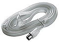
Wire antenna (rolled up folding dipole for VHF reception).

Active indoor antenna for VHF and UHF reception
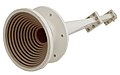
Grooved horn radiator (surface antenna)

Group antenna of six Yagi antennas with crossed dipole for satellite communication.

Parabolic antenna with a diameter of 2.70 m
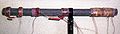
Ferrite antenna with coil set for long, medium and short wave

Loop antenna from the early days of radio reception

Installation of a phased array radar

Antenna top of the Stuttgart TV tower

Parabolic antenna of the weather radar "Meteor 1500 S" in Adelaide (Australia)

VDF-Groß-Basis Doppler DF antenna of the German air traffic control on the Deister near Hanover

NVIS antenna on a Fuchs M93A1 "FOX" tank


.JPG)


See also
- Frequency bands
- Antenna pair , antenna diversity
- Antenna splitter
- MIMO (Multiple Input Multiple Output)
literature
- Günther Grünbeck: The antenna construction kit. Antennas, accessories and measuring devices built in-house (= radio technology consultant). Verlag für Technik und Handwerk, Baden-Baden 2003, ISBN 3-88180-394-7 .
- Albrecht Hock, Arastou Tscharmi: Antennenpraxis. An introduction to the world of antennas. Seeing, recognizing and understanding . Expert-Verlag, Renningen-Malmsheim 1995, ISBN 3-8169-1150-1 .
- Paweł Kabacik: Reliable evaluation and property determination of modern-day advanced antennas Oficyna . Wydawnicza Politechniki Wrocławskiej, Wrocław 2004, ISBN 83-7085-765-5 .
- Manfred Loidiller: Safety requirements for antennas and cable networks . VDE-Verlag, Berlin / Offenbach 2005, ISBN 3-8007-2784-6 .
- H. Meinke, FW Gundlach: Pocket book of high frequency technology . Fourth edition. Springer-Verlag, Berlin 1986, ISBN 3-540-15393-4 .
- Karl Rothammel: Rothammels Antennenbuch . Newly edited and expanded by Alois Krischke. 12th updated and expanded edition. DARC-Verlag, Baunatal 2001, ISBN 3-88692-033-X .
- Lothar Starke, Herbert Zwaraber: Practical construction and testing of antenna and distribution systems. 14th edition. Hüthig, Heidelberg 2002, ISBN 3-7785-2897-1 .
- Martin Gerhard Wegener: Modern radio reception technology . Franzis-Verlag, Munich 1985, ISBN 3-7723-7911-7 .
- Otto zince , Heinrich Brunswig: high frequency technology. Vol. 1 and 2. Springer-Verlag, ISBN 3-540-66405-X and ISBN 3-540-64728-7 .
- Wolfgang Burkhardtsmaier: Antenna and system technology at AEG , Heidelberg: Dr. Alfred Hüthig Verlag 1987.
Web links
- Collection of images of various antenna designs ( memento from February 1, 2012 in the Internet Archive )
Individual evidence
- ↑ THz Research - Experimental Semiconductor Physics. Philipps University of Marburg, accessed on August 23, 2016 .
- ↑ mpg.de 1.5 THz astronomy.
- ^ Albrecht Fölsing: Heinrich Hertz. Hoffmann and Campe, Hamburg 1997, ISBN 3-455-11212-9 , p. 275.
- ↑ Quotes from the www: Nikola Tesla - inventor, scientist and fantastic
- ^ Friedrich Kluge: Etymological dictionary of the German language . 22nd edition, De Gruyter, Berlin / New York 1989, p. 32f.
- ↑ Jost Trier : antenna . In: Ulrich Engel et al. (Ed.): Festschrift for Hugo Moser: For his 60th birthday on June 19, 1969. Pädagogischer Verlag Schwann, Düsseldorf 1969, pp. 193–201, and the like. A homological function metaphor of modern technology: antenna , in: Jost Trier: ways of etymology . Edited by Hans Schwarz. Erich Schmidt Verlag, Berlin 1981, pp. 118–125.
- ↑ A DESIGNERS GUIDE TO SHIELDING (PDF; 2.6 MB)
- ↑ RADIATION AND ANTENNAS (PDF; 819 kB)
- ↑ Dominik Liebich: Active antenna from 10kHz to 50MHz according to DB1NV. (PDF; 179 kB) (No longer available online.) Darc.de, April 6, 2005, archived from the original on July 1, 2015 ; accessed on August 23, 2016 .
- ↑ Otto Zinke, Heinrich Brunswig, Anton Vlcek, Hans Ludwig Hartnagel, Konrad Mayer: High frequency technology. Electronics and signal processing. 1999, ISBN 3-540-66405-X (limited preview)
- ↑ Committee for lightning protection and lightning research of the VDE (ABB): ABB leaflet 16: Lightning protection systems or antenna earthing for radio transmission / reception systems 2008.
- ↑ Peter Bruger, Bernd Buchmann, Karl-Eugen Kurrer , Claudia Ozimek: Rotatable shortwave curtain antenna operable at very high wind speeds , in: IEEE Transactions on Broadcasting, Vol. 42, No. 1, March 1996, pp. 50-54