
Feather (technology)


A feather is an i. d. Usually a metallic technical component that can be deformed sufficiently elastically in practical use . The most commonly used spring is the coil spring, a wire wound in a helical shape .
Working principles
The elastic deformation of springs is mostly a bend or a torsion. A bending moment leads to bending stresses , or a torsional moment leads to torsional stresses . Consequently, springs are primarily either spiral springs or torsion springs . The other deformations -
- Elongation (or compression) under normal force ( tensile force (or compressive force )) that leads to tensile stress (or compressive stress ) and
- Shear under shear force , which leads to shear stress -
always occur simultaneously, but to a lesser extent.
The bend is not an independent deformation, but on the one hand an expansion (in the arch-outer part of the cross-section) and on the other hand a compression (in the arch-inner part of the cross-section).
In the case of bending and torsion, the deformation path (or angle) that results from the non-uniform stress on the cross-section (stress in the center equal to zero), is relatively high, which is why bending and torsion springs are preferably used technically.
history

Simply shaped, resilient bodies, such as the wooden bow for shooting arrows, were already used by humans in prehistoric days. In the Bronze Age , there were already more complex, resilient structures such as tweezers and fibula in many cultures . Ktesibios of Alexandria produced bronze with special elastic properties as an alloy with an increased tin content , which was hardened by hammering after casting.
Tensionable ( windable ) springs wound from sheet metal strips have been used to drive table clocks since the early fifteenth century, and pocket watches from the transition to the sixteenth century. The spiral spring in the clock-setting balance was built into pocket watches by Salomon Coster from 1673 (inventor was Christiaan Huygens ).
In 1676 the British physicist Robert Hooke formulated Hooke's law on which elastic deformation is based : The deformation is proportional to the load .
Applications
All uses of the spring are based on its ability to store potential energy .
- Drive energy: The energy of a pretensioned ( wound ) spring is used to drive moving devices such as mechanical watches . The drive stops when the spring is relaxed again.
- Restoring force : spring force as a counter force, for example in spring balances , moving coil measuring mechanisms or torque wrenches .
- Frictional connection : The restoring force of a pretensioned spring is often used for the normal force required for a frictional connection, for example in friction clutches or door stops .
- Evasive part when the shape of other components changes: Components whose dimensions change during operation are often designed to be resilient or installed in combination with a spring in order to avoid constraints, for example in the event of thermal expansion or harmful play, for example in the event of wear and tear. Wear in a friction clutch only leads to slightly less pressing of the friction surfaces against one another, not to an interruption of contact. When using an expansion screw, the preload increases to a tolerable degree in the event of thermal expansion. When the part fastened with the screw is plastically yielding (setting), the screw does not become loose.
- Load distribution: Large-area load transfer between bodies is more even, the more elastic the body or one of the bodies are. An example is the innerspring mattress , in which several springs are pretensioned when loaded.
- Part of an oscillating spring-mass system: Kinetic energy deforms the spring, after which this energy is present as potential energy. The mass swings out until all kinetic energy is transformed into potential energy. After that, the energy conversion is opposite, and the mass swings back into the opposite end position.
- A body is resiliently mounted in order to mitigate the effect of impacts, i.e. high, short-term forces acting on it. So that the vibration dies away quickly, it is dampened, as is the case with the suspension of a vehicle with shock absorbers .
- The permanent oscillation of a body is achieved through its combination with a spring, for example that of the unrest of a mechanical watch coupled with a spring. The damping caused by friction in the pivot bearings of the balance is compensated for by supplying the oscillating system with a small amount of energy from the mainspring of the watch with each deflection.
materials
Springs are made from steel ( spring steel ) and copper alloys (mostly beryllium copper ). The semi-finished products are mainly narrow strips and wires. There are no standardized springs made of other elastic materials such as rubber and fiber-reinforced plastic . Gas pressure springs are usually also custom-made.
Parameters

To characterize springs, the spring constant ( spring hardness ) or the spring characteristic is specified. These describe the relationship between deformation (distance s or angle φ ) and force F or torque M t . Like Hooke's law on which it is based, the spring characteristic is linear to a good approximation (→ spring constant , see 2 in Fig.). For special purposes, non-linear characteristics, often implemented in a special way, are used.
Characteristic curve examples:
- Pressed rubber springs (rubber blocks) basically have a progressive characteristic curve ( 1 ).
- Modern sports bows have a degressive spring characteristic ( 3 ). The area under the characteristic corresponds to the stored energy. With the same holding force, this is greater than with a linear characteristic.
- With a car clutch , the pedal force should not increase too much over the pedal travel ( 4 ), for which a pre-tensioned diaphragm spring is suitable.
- The vehicle suspension is often progressive designed ( 1 ) to prevent strike-through at a high load, while at normal load, a soft, comfortable suspension is desired. The hardening of the spring occurs when the larger coils lie on top of one another and thus shorten the effective spring length. A two-stage winding, which is a little easier to manufacture, serves the same purpose. An approximation can also be achieved by placing two different springs one behind the other ( 5 ).
- Discontinuous gradients also arise in leaf springs with a curved cross-section, such as the crackling frog ( 5 ).
Deformation equations
Spiral spring
A flexible rod extended in the -direction assumes the curvature when stressed by the bending moment in the -plane :


- ( : Modulus of elasticity of the material : area moment of inertia when bending around the axis)


Torsion spring
The torsion angle of a rod of the length when loaded with the torsional moment is:


- ( : Shear modulus of the material : polar area moment of inertia of the cross section)


Spiral springs
Most spiral springs are leaf springs (rectangular cross-section), wire springs are in the minority. Straight ( stretched ) spiral springs can be treated with the beam theory that applies to straight beams . Two special features must be observed for the predominantly curved spiral springs:
- The stress distribution in the cross-section is no longer symmetrical, as with straight springs. The tension of the concave edge fiber is increased, which must be taken into account with the help of correction factors.
- When creating the curvature, the permissible stress is reduced if there is no post-heat treatment.
Leaf spring

Coil springs
Spiral springs are metal strips that are wound in a helix in a plane and are therefore strongly curved. They are the main component of spring-driven watches . Their even sequence is achieved with mechanical auxiliary devices ( escapement , friction speed controller ). Later they were also in Gramophone , film cameras and telephones with dial built. In toys they become spring motors that i. d. They are usually more simply constructed and run unevenly quickly or are regulated by a flywheel .
The escapement of the mechanical watch contains the balance spring as a balance spring .
A special spiral spring drive is the scroll spring drive , in which a spiral spring is moved back and forth between two housings (drums). In a preferred embodiment, the spring has a different curvature in the two drums and thus stores more energy than with a one-sided curvature. When the drive is pulled up, the spring is wound up in the output drum. As it expires, the spring retracts into the supply drum to assume its original shape, driving the output drum in the process. This spring drive is z. B. used to roll up power cords in vacuum cleaners .
The spiral spring is also often called a scroll spring in other spring drives .
Elliptical spring
The slightly curved leaf springs that have been used in vehicles since the spring-loaded carriages were often used in pairs mounted against one another. This pairing to an elliptical shape resulted in the designation elliptical spring . The two opposite springs are usually spring packages, i. H. individual spring leaves lying on top of one another. Because of the central load, the bending moment is greatest in the middle of the spring length. The stepped longitudinal shape of the spring assembly is adapted to the triangular moment curve: the length of the added leaves decreases from piece to piece.
Which takes place predominantly at the ends of the sheets against their neighbor leaves friction for vibration - damping of the spring-vehicle body system utilized.
- If the full elliptical spring is "trimmed", the shapes that are also used are created:
- Three-quarter elliptical spring (half of one of the two packages is removed, the remaining half is firmly clamped),
- Semi-elliptical spring (only one of the original two packages is used),
- Quarter-elliptical spring (half of the semi-elliptical spring is removed, the remaining half is firmly clamped, for the wheel suspended from it it acts as a cantilever beam → cantilever spring )
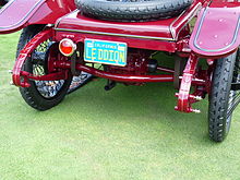
Three-quarter elliptical pen, De Dion-Bouton
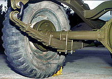
Semi-elliptical spring, jeep

Quarter elliptical spring as wishbone
Actually i. d. Usually a semi-elliptical spring is installed, the halves of which are a quarter-elliptical spring for each wheel.

.jpg)

.jpg)

Parabolic spring
Instead of forming a stepped spring package, a leaf spring with a parabolic strength decreasing from the center to the ends can be used.
A spring leaf with a trapezoidal shape acts in a similar way (adjacent figure).
Wave spring
Wave springs are corrugated rings made of flat wire. The waves are leveled under load. The springs can be stacked in packages to replace coil springs (up to half the installation space, but the same diameter). As a single layer, they are used, for example, in bayonet locks and shaft bearings to compensate for axial play.
Wire spring
For the above-described applications of leaf springs (rectangular cross-section), wires (round cross-section) are hardly used because of their flexibility on all sides.
Needle spring
The needle spring is a straight or only slightly curved, flexible short piece of wire. Needle springs are used, among other things , in the construction of musical instruments , for example in the construction of the key mechanism of woodwind instruments .

Wave spring
As an exception, wave springs (see above) are also made from wire with a round cross-section.
Leg spring
Torsion springs are helically wound ( wound ) wire springs with protruding straight ends ( legs ). The legs serve to introduce the torque that bends the wire. With many coils, it is guided on an inserted cylinder or with half-shells (see clothes peg ) from the outside against the tilting moment that occurs
Examples of use are: safety pin (picture opposite), clothes peg, mousetrap with striker.
Torsion springs
Most torsion springs are made of rods or wire with a round cross-section. Other cross-sections (square, rectangular, etc.) are in the minority. In contrast to the straight ( stretched ) torsion springs ( torsion bar springs ), two special features must be taken into account when handling the coiled torsion springs ( coil springs ):
- The stress distribution in the cross-section is no longer rotationally symmetrical as with straight springs. The tension in the inner edge fibers is higher than that in the outer fibers, which must be taken into account with the help of correction factors.
- When creating the curvature, the permissible stress is reduced if there is no post-heat treatment.
Rod spring
Examples of torsion bars used are the torsion pendulum in mechanical watches , the torsion band in moving coil measuring instruments (for generating the reaction torque and as a bearing element for the moving coil) and the stabilizer and the torsion bar spring for vehicle suspension.
Coil spring
In the case of the helical spring, the spring wire is coiled ( wound ) in a helical shape . A distinction is made between coil tension and compression springs . The springs are pulled apart or compressed in the direction of the screw axis and are briefly referred to as tension or compression springs. In coil springs mainly torsional stresses arise, not tensile or compressive stresses, which could be wrongly deduced from the terms tension and compression spring.
The outer contour is cylindrical, conical or barrel-shaped. A compression spring in one of the latter two forms can be compressed severely because the coils are partially nested: a mini-block spring .
To prevent the end turns from tilting under load, the force must be applied centrally. The eyes of the tension springs are bent so that they lie in a central plane. With compression springs, about 3/4 of the two end turns are usually applied to the adjacent turn ( non-resilient turns ) and ground off at right angles to the spring axis. This creates a three-quarter circular flat surface.
In safety-critical applications, only cylindrical compression springs are used, since with them, with the appropriate structural design, the breakage of the spring means that only one less coil of the spring applies the spring force, so that most of the spring action is retained.

Part of a railroad car supported on pressed coil springs

Conical springs ( coiled springs )

Tension spring with central eyelets

Compression spring , end turns bent and sanded off


The coil spring is a coiled torsion bar. The spring coils are bent to a negligible extent. In their design, only the torsional stress is taken into account (the bending stress is negligibly small). The equation given above for the torsion bar
is in the well-known "hand equation" for springs made of round wire
- (with : spring constant : loading force, : travel, : shear modulus , : wire diameter : mean spring diameter : the number of resilient turns )


for handling the coil spring, as the following changes show.
Between rotation and travel , there is a relationship:
The onerous torque is of the centrally acting force generated: .
The stretched length of the wound wire is the circumference of a winding multiplied by the number of turns : .
The polar moment of inertia of the circular area is .


Inserting these four expressions into the torsion bar equation gives:
- ,

which is identical to the “hand equation” sought.
Disc springs

Form and function
A disc spring has the shape of the shell of a flat truncated cone . It is elastically compressed between its peripheral circles (theoretically until it is maximally deformed into a flat disk), whereby normal stresses (compressive and tensile stresses) are formed in the material as a reaction to the forces introduced .
With the usual arrangement of disc springs, a progressive increase in the spring force occurs when the spring travel exceeds 75%, deviating from the calculation. This is caused by the shifting of the force application points to smaller lever arms because the disc springs roll over one another or on the contact surface . This can local over the spring material stresses encourage and spring fractures lead. It is therefore recommended to only use approx. 75 to 80% of the spring travel. For this reason, in DIN 2093 the spring forces are only given for 75% of the spring travel.
Since compressive stresses (-) occur at r i (above in the adjacent figure) , but tensile stresses (+ ) occur at r a , the deformed disc spring is not only a flat, but also a slightly curved truncated cone along a surface line . At r 0 is the transition from compressive to tensile stress, no stresses occur there.


Combinations
The single disc spring is a relatively hard spring and is used accordingly. A softer spring is created by alternately stacking the plates ( series connection ). This is an application advantage when it comes to producing a softer nib from “catalog parts”. By same direction stacking ( parallel connection ) a spring which is harder than the single spring is formed.
Materials
- designated spring steels in sheet metal form such as C60S (1.1211), C67S (1.1231) and C75S (1.1248) or 51CrV4 (1.8159)
- corrosion- resistant steels such as X10CrNi18-8, X7CrNiAl17-7, X5CrNiMo17-12-2, X5CrNi18-10
- Creep resistant steels such as X22CrMoV121 or X39CrMo17-1
- Copper (CuSn 8, CuBe 2) and nickel alloys (Nimonic, Inconel , Duratherm)
- fiber-reinforced plastics (FRP) in individual cases.
In order for disc springs to retain their spring properties (high elasticity or toughness with high strength ), disc springs made of common spring steels are heat-treated ( quenched and tempered ) after their manufacture or made directly from spring-hard material (group 1 from strip material, see below). According to DIN 2093, the hardness must be between 42 and 52 HRC .
Manufacturing
According to DIN 2093, a distinction is made between three production groups:
- Group 1: Disc springs with disc thickness <1.25 mm: punched or fine-cut from strip material
- Group 2: Disc springs with a disc thickness of 1.25 to 6 mm: punched or finely cut. With punched disc springs, the inner and outer diameters are turned after punching in order to remove punch marks ( notch effect ).
- Group 3: Disc springs with disc thickness over 6 mm: made of hot-formed blanks, the surface is completely turned.
For small quantities, disc springs can also be lasered from strip material .
Norms
- DIN EN 16984 - calculation (up to 2/2017: DIN 2092)
- DIN EN 16983 - quality requirements, dimensions (up to 2/2017: DIN 2093)
Application examples
- in friction clutches to generate the normal force (see also diaphragm spring below)
- in disc brakes as return springs
- to compensate for the game , e.g. B. axially wrestle with ball bearings that are installed with a loose fit
- as a drive for circuit breakers in high voltage .
Other metallic springs
The following springs are designs that have been developed for specific purposes and are rarely used in general.
Evolute spring
The Evolutfeder , also buffer spring , coil spring , helical spring or conical spring called, is of a flat strip wound helically overlapped. The resulting truncated cone is elastically compressed axially (in the longitudinal direction of the ribbon cross-section). The band cross-section is twisted, which is why a relatively hard spring is created. The spring characteristic is non-linear.
It was invented by John Baillie in 1846 and used as a railroad buffer spring. It replaced the older helical spring (see above) and was later replaced by ring springs (see below).
Today, it is only as a double-Evolutfeder ( flat pattern is a V-shaped sheet-metal cutout) in garden shears frequently.

Evolute spring

Evolute spring in a railway buffer

Double evolute spring ( series connection )

Double evolute spring in secateurs


Ring spring


The ring spring is now the standard spring in railway buffers. It is extremely tough. An applicable spring is therefore a stack of inner and outer rings arranged in a row.
When compressed, the larger outer rings are stretched and the smaller inner rings are compressed. They slide into one another at the truncated conical contact points, the resilient movement being dampened by friction. Due to the additional damping, an annular spring package can achieve a degree of utilization (η A ) of more than one.


Diaphragm spring
Diaphragm springs are thin, elastic, mostly circular plates.
In automotive engineering , a diaphragm spring is the type used in a mechanical clutch of a motor vehicle. In the inner area, the slightly conical ring is divided into radial tongues. These serve as actuating levers to turn the edge area inside out to release the coupling. When not turned inside out, the pre-tensioned edge ring, comparable to a disc spring, represents the normal force of this frictional coupling.
A barometer box consists of two concentrically corrugated circular membranes that move elastically against each other when the air pressure outside the box changes .
Expansion screw
An expansion screw is relatively long and has a slim shaft. It is an elastic component that works like a relatively hard tension spring, but is not called a spring.
Non-metallic springs
Rubber spring
Rubber springs are often massive blocks - sometimes bands - made of rubber or elastic plastic ( elastomer ). These materials have a spring stiffness or modulus of elasticity that is orders of magnitude lower than that of metal . Their damping properties are higher, which is why they are often used to decouple mechanical and acoustic vibrations. So-called silent blocks usually have metal parts vulcanized onto two opposite sides, with the help of which they are attached between two components that are spring-loaded against each other. A so-called silent bushing, together with a metallic axle, forms a rubber bearing , i. H. an elastic pivot bearing , e.g. B. in the suspension of motor vehicles.
Rubber springs were used for the vehicle suspension of the BMC Mini . In addition to the actual (metallic) springs, additional springs made of polyurethane (PUR) or microcellular urethane ( MCU ) for the end stops of the wheel suspensions can be found in motor vehicles . It is a plastic foam that is compressed under load. The characteristics of such an additional spring are largely determined by the shape and additional support elements such as plastic rings. The common material used for rubber springs is not compressible. The thickening of a pressed rubber block must not be hindered at the installation site.

Air spring
In the case of an air spring, the compressibility of air is used . Simple examples are the air mattress and the pneumatic tire , a more complex one are the systems used for vehicle suspension.
The following advantages come into play in vehicles compared to metallic springs:
- Sensitive response as there is almost no self-damping.
- Pre-selectable and / or automatically adjustable pre-tensioning by means of a compressor on board: This allows the height of the vehicle body to be adjusted or held independently of the load. It should be noted, however, that the suspension becomes harder with greater preload.
Gas spring
Gas pressure springs are closed gas-filled springs with increased internal pressure (preload). They are used, for example, on the trunk lid of automobiles and in spring-loaded office chairs.
See also
- Stiffness , modulus of elasticity, modulus of shear
- Suspension (vehicles)
- Rubber motor (rubber band as spring accumulator)
- Spring-loaded accumulator (spring-loaded brake)
- Spring mechanism (drive, especially of mechanical watches)
- Spring steel as the most common material for springs
- Bimetals are sometimes referred to as bimetallic springs.
- Slinky (coil spring as a toy)
Web links
- Association of the German spring industry , with an illustrated list of spring types
- Mechanical spring calculators , calculation of mechanical springs
- VDF springs: history of the spring
Individual evidence
- ^ Siegfried Hildebrand : Feinmechanische Bauelemente , Hanser 1968, p. 289, storage elements: springs.
- ↑ Hildebrand, 1968, p. 299.
- ^ Helmut Kahlert , Richard Mühe , Gisbert L. Brunner : Wristwatches: 100 years of development history. Callwey, Munich 1983; 5th edition, ibid. 1996, ISBN 3-7667-1241-1 , pp. 36-38.
- ↑ Hildebrand, 1968, pp. 306-308.
- ↑ techniklexikon.net: leaf spring .
- ^ TFC: a manufacturer of wave springs .
- ^ Bohnert GmbH: a manufacturer of wave springs .
- ↑ Hildebrand, 1968, p. 309.
- ↑ Günter Dullat: woodwind instruments . In: Edition Moeck . tape 4040 . Moeck, 1990, ISBN 978-3-87549-032-9 , pp. 52 ( google.de [accessed on October 22, 2017]).
- ↑ Hildebrand, 1968, p. 315.
- ↑ In the suspension of vehicles, helical compression springs are often supported in plates with a helical recess in the floor. Long compression springs need a guide so that they cannot buckle.
- ↑ Bosch : Kraftfahrtechnisches Taschenbuch , VDI-Verlag, 1984, 19th edition, p. 228
- ↑ F. Dubois: About the strength of the cone shell , dissertation at the ETH Zurich, 1913
- ↑ P. Bühl: Stress calculation of disc springs , DRAHT 22 (1971) 11, pp. 760–763.
- ↑ Bischoff (a spring manufacturer): Technical drawing ( sheet metal development and two views ) of a truncated cone spring [1] .
- ↑ In the manner of a bandage around the finger, arm or leg.
- ↑ Albert Albers: Fundamentals of the calculation and design of machines . In: Waldemar Steinhilper (ed.): Construction elements of mechanical engineering . 8th edition. tape 1 . Springer-Verlag, Berlin / Heidelberg 2012, ISBN 978-3-642-24300-4 , 5.1.2.3 Degree of utilization, p. 206, 224 .
- ↑ kfz-tech.de: air suspension .