microphone
A microphone or microphone is a sound transducer that converts airborne sound as sound pressure fluctuations into corresponding electrical voltage changes as a microphone signal. This distinguishes microphones from pickups that convert solid -state vibrations. Underwater microphones are called hydrophones .
In the usual design, a thin, elastically mounted membrane follows the pressure fluctuations of the sound. Through its movement, it simulates the temporal distribution of the alternating pressure. A converter, which is mechanically or electrically coupled to the membrane, generates an audio frequency AC voltage corresponding to the membrane movement or a corresponding pulsating DC voltage .
History of the Microphone
Developments in the microphone
The development of the microphone went hand in hand with the development of the telephone . The basic transducer principles are listed in the historiography, and the various acoustic designs resulted from the improvement of individual models.


The Italian engineer Antonio Meucci , who emigrated to the USA , developed a telephone back in 1860 based on an electromagnetic converter that he had also invented. However, he was not a successful businessman and was not granted a patent. Alexander Graham Bell , a Scottish teacher for the deaf and mute, who is often cited today as the inventor of the microphone and worked in the laboratory in which Meucci's invention was kept, applied for a technically similar patent on February 14, 1876. In 1887, the United States government instituted proceedings to annul the patent. However, this was discontinued after Meucci's death and the patent expired.
In the course of developing what he called the "telephone", Philipp Reis was the first to build a contact microphone, which he first presented to the public in 1861 as part of his telephone prototype. Based on the model of an auricle, Reis realized that instead of an eardrum, a sound funnel covered with a membrane could also be used. With Reis, this bell ended in a housing box. He fitted the membrane with a platinum contact which, when at rest, just touched another contact fixed in the housing. Direct current was conducted via this contact and an external resistor . If an alternating sound pressure took place on the membrane, it began to vibrate, which meant that the contacts were more or less compressed depending on the course of the sound waves . With this experimental set-up, Reis invented the contact microphone, from the principle of which the carbon microphone was later developed, which was used for recordings in the early days of radio.
The realization that carbon can very easily convert the vibration of a membrane into electrical impulses led to the development of the carbon microphone at the end of the 19th century . In 1877, Emil Berliner developed a sound transducer at Bell Labs , USA, which used the pressure-dependent contact resistance between the membrane and a piece of carbon to generate a signal. However, David Edward Hughes is regarded as the inventor of the carbon microphone, who first publicly presented a similar development based on carbon rods on May 9, 1878 at the Royal Academy in London. Hughes was also familiar with Philipp Reis's contact microphone because he had experimented with an imported telephone from the German inventor in 1865 and had achieved good results.
In the same year, the Englishman Henry Hunnings improved the microphone by using grains of carbon instead of carbon sticks. In 1890, Anthony C. White constructed the carbon microphone in the form in which it basically remained unchanged for the next 100 years . This "carbon grain microphone" was used as a studio microphone until the 1940s; it is now regarded as the first "real" microphone and was only superseded by the condenser microphone . A common carbon microphone was Eugen Reisz 's marble block or Reisz microphone .
Georg Neumann , a Reisz employee, further developed the carbon microphone in 1923, greatly improving the sound quality, especially at low frequencies. However, his breakthrough came with the development of the low- frequency (AF) condenser microphone . Membrane and counter-electrode form a capacitor that is charged to a DC voltage; The membrane movement changes the capacitor capacity, from which the signal is obtained. This transducer principle was qualitatively far ahead of the sound recording technology of its time and is still the standard for microphones of the highest quality today.
In 1928, Georg Neumann founded a company in Berlin to market his condenser microphones, Georg Neumann & Co KG , which is still one of the leading microphone manufacturers today. The first functional series model, the Neumann CMV3 , also known as the "Neumann bottle", can be seen on many contemporary film recordings. The first microphone with an electrically switchable directional characteristic , the Neumann U47 from 1949, is also legendary. It is still one of the most sought-after and expensive microphones today: a functional, well-preserved U47 is traded for around 5000 euros.
From 1920 radio broadcasting came into existence . Stage actors and cabaret artists, who now appeared on the radio, found the microphone irritating. Speaking to a microphone instead of an audience took some getting used to; moreover, by the late 1920s, microphones were already so sensitive that it was no longer necessary to shout into them. The 1929 BBC Hand Book devotes a separate chapter to the microphone , entitled "My Friend Mike " :
- "I've known Mike for a long time. I first met him in 1922. He didn't have a throne then, just hung around. I think he's very sensitive because they wrap him in cotton towels. I like Mike because he always speaks so well of me and is never sick and introduces me to people I would never have met without him.”
In 1962, Gerhard M. Sessler and James Edward Maceo West invented the electret microphone , a variant of the condenser microphone that is the most common type of microphone today, accounting for 90 percent of the market. Gerhard M. Sessler and Dietmar Hohm also invented the silicon microphone at the TH Darmstadt in the 1980s .
Manufacturer
Other names that appear in the development of the microphone are: David Edward Hughes , Sidney Shure , Fritz Sennheiser , Eugen Beyer.
Major dynamic microphone manufacturers: Sidney Shure , Electro-Voice , Sennheiser , Beyerdynamic (specialty: ribbon microphones), AKG Acoustics .
Important manufacturers of condenser microphones: Sidney Shure , Georg Neumann GmbH Berlin (belongs to Sennheiser since 1991), Sennheiser (speciality: HF condenser microphones), Microtech Gefell GmbH (in Gefell , formerly Neumann & Co. KG , later VEB Microphone Technology ). Gefell ), Schoeps , Danish Pro Audio (formerly Brüel & Kjaer ), AKG Acoustics , Brauner Microphones.
Important manufacturers of measurement microphones: Brüel & Kjaer, GRAS, Microtech Gefell GmbH, Norsonic, PCB Piezotronics.
converter principles
Depending on the acoustic design of the microphone, the membrane follows the sound pressure ( pressure microphone , omnidirectional microphone) or the sound pressure gradient ( pressure gradient microphone , directional microphone). The converter principle is decisive for the technical quality of the microphone signal, which is characterized by the signal-to- noise ratio , impulse fidelity , distortion factor and frequency response .
Microphone transducers can be categorized as follows:
Dynamic microphones
The dynamic microphone works on the principle of electromagnetic induction . From a technical point of view, the speed of the membrane movement in the dynamic microphone leads to the signal, not the momentary deflection, which is why it is also referred to as a speed receiver . The main area of application for dynamic microphones is the live area . In addition to live use, the dynamic microphone is also used to mike drums (snare drum, cymbals, tom-toms, etc.), and occasionally for vocal or instrument recordings.
moving coil microphone
The moving coil microphone is a type of dynamic microphone. The term refers to the structure of the transducer: With moving coil microphones, the membrane is firmly connected to a coil ( moving coil ) as in an electrodynamic loudspeaker , which is moved by the movement of the membrane in a permanent magnetic field (air gap of a pot magnet). The relative movement of the coil and magnetic field generates the signal voltage through induction. The advantages of this type of microphone are:
- relatively robust against mechanical loads
- tolerates high sound pressure levels (advantageous for singing and loud instruments)
- does not require a power supply
- is relatively inexpensive.
Due to the mass of the coil, moving coil microphones have a limited reproduction spectrum and poor impulse response. They are good for close-up photography because their non-linear distortion is low even at high sound levels.
ribbon microphone
A ribbon microphone is a type of dynamic microphone. With this type of microphone, the transducer principle and acoustic functionality are closely linked.
The membrane of the ribbon microphone is a zigzag-folded strip of aluminum two to four millimeters wide and a few centimeters long. It is only a few microns thick. When excited by incoming sound , the movement in the magnetic field induces a voltage corresponding to the speed of movement, which can be tapped at the ends of the aluminum strips.
Ribbon microphones have an almost linear frequency response in the working range ; their extremely light membrane gives them good impulse behavior . Due to the principle, the sound can reach the membrane from both sides. The acoustic design is therefore that of a pressure gradient microphone. From this follows the directional characteristic of an eight. Ribbon microphones are not suitable for recording the lowest frequencies.
condenser microphone
The condenser microphone works according to the physical principle of the condenser . Since the diaphragm deflection and not the diaphragm speed leads to the signal, the condenser microphone is technically an elongation receiver .
Condenser microphones come in a wide variety of forms, since this term only refers to the converter principle. However, the term has established itself colloquially as a microphone class, since tonal properties are closely linked to the principle of conversion.
principle

In the case of the condenser microphone, an electrically conductive membrane a few thousandths of a millimeter thick is attached in front of a metal plate with electrical insulation. From a technical point of view, this arrangement corresponds to a plate capacitor , which has an electrical capacity . Incoming sound causes the membrane to vibrate, which changes the distance between the two capacitor foils and thus the capacitance of the capacitor. Such devices can also be implemented as microsystems .
Low-frequency technology (LF technology)
As soon as an electrical voltage is applied, a potential gradient is created between the membrane and the plate . With a high-impedance supply (typically in the gigaohm range), the capacitance fluctuations lead to voltage fluctuations with an essentially constant charge on the capacitor – an electrical signal. The capacitance of the capsule and the supply resistance form a high-pass filter as an RC element, which limits the lowest frequency that can be transmitted. A voltage source is required to achieve the potential drop between the capacitor plates and to supply the microphone amplifier ( impedance converter ). Usually, the 48-volt phantom power of the microphone preamp or mixer is used ; see also: Balanced signaling .
High frequency technology (HF technology)
Alternatively, the capacitance of the capacitor can also be measured using HF technology. For this purpose, the impedance can be measured, in particular in a measuring bridge with phase-sensitive reading, or the capsule is used as a frequency-determining component in an oscillator. This eliminates the restriction to high-impedance follow-up amplification. It is also possible to generate a signal down to any low frequency (actually the microphone is then a fast barometer). The capsule is optimized for other parameters than with NF technology, it must z. B. be less voltage-proof. The circuit complexity is usually higher than with NF technology. If the power supply is not clean (with remnants of the clocking of a switch generator for the phantom power), interference can occur due to intermodulation. Here, too, the circuit is usually supplied via phantom power.
polar patterns
Condenser capsules are used both as a pressure microphone and as a pressure gradient microphone. Some condenser microphones have a switchable polar pattern . This is made possible by combining two pressure gradient microphones (double gradient microphone).
Because of the high signal quality, the condenser sound converter is the recording standard in recording studios today. However, it is quite sensitive (especially to moisture of any kind) and can even be damaged by very high sound pressure. Dynamic sound transducers therefore dominate in the sound reinforcement and live area.
Electret condenser microphone
The electret microphone is a special type of condenser microphone. An electret foil is applied to the capacitor plate opposite the membrane, in which the electrical membrane pretension is “frozen”, so to speak. Some microphone capsules contain a microphone amplifier ( impedance converter ) for the low signal currents. Simple microphones require a low operating voltage of 1.5 volts. The current requirement of 1 mA favors the use in mobile devices and on/in computers.
Such electret microphones are not suitable for high sound pressure levels; the low supply voltage limits the possible transmittable sound level. Modern electret microphones are also used for studio and measurement purposes.
carbon microphone
A carbon microphone is an electroacoustic converter principle in which the pressure fluctuations of the sound cause changes in electrical resistance. The pressure-dependent transition resistance in the carbon granules stored behind the membrane is used for the conversion.
Carbon microphones have poor reproduction properties; the mass of the metal cone limits and distorts the frequency response, the carbon grains cause noise, especially when moving. The non-linear relationships between pressure and contact resistance of the carbon grains result in non-reproducible, non-linear distortions.
The main advantage of the carbon microphone is its high output signal - in a DC circuit it delivers a signal sufficient for long-distance transmission and playback with an electromagnetic earpiece. Reinforcement is not necessary.
Carbon microphones were therefore used in large numbers in telephones in the past . It is believed that the invention of the carbon microphone greatly accelerated the development of telephony. After a certain time, the charcoal granules became compacted in the microphones of the telephones, which led to a significant reduction in voice quality. For this reason, dynamic capsules or electret capsules with an additional circuit for amplification and signal conditioning have been used since the 1970s. These modules could replace the carbon microphones in phones without changing the circuitry.
In professional audio engineering, the carbon microphone was already being replaced by the condenser microphone in the 1920s and 1930s . In communications technology, the electret microphone dominates the market today.
Piezo or crystal microphone
A piezo microphone is a type of microphone whose transducer principle is based on the properties of piezoelectric elements. A membrane follows the pressure fluctuations of the sound. It is mechanically coupled to a piezoelectric element. It is minimally deformed by the pressure fluctuations and outputs them as electrical voltage fluctuations. The piezo ceramic lead zirconate titanate (PZT) is usually used as the piezoelectric material.
Such microphones were popular in the 1930s to 1950s. They are mechanically robust and have advantages due to their simple design. A major disadvantage of this converter technology is the high distortion factor . In principle, they are not suitable for high-quality recordings and have not been able to assert themselves against the carbon microphone in telecommunications technology . Vibration conversion using piezoelectric elements, on the other hand, is widespread in contact sound transducers ( pickups in turntables and for instruments, structure-borne noise pickups, vibration pickups). The forces available here are generally much greater and lead to better transmission properties than is the case with airborne noise.
Acoustic designs
The acoustic design is decisive for the directivity and the frequency response. In contrast to loudspeakers , the diaphragm size of microphones plays no role with regard to their bass reproduction, since microphones, like the human ear , only act as sensors and do not have to compress air in the low-frequency range with the smallest possible excursion like loudspeakers. An exception are infrasound sensors.
polar pattern
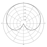
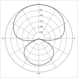
In microphone technology, the directional characteristic describes the sensitivity of a microphone in the form of a polar diagram , i.e. the output voltage in relation to the sound pressure, depending on the angle of incidence of the sound . One can differentiate between the conditions in the direct field and in the diffuse field .
The directional characteristic depends on the acoustic design of the microphone capsule and external form elements (e.g. boundary layer microphone , shotgun microphone ). The strength of the directivity is described by the degree of bundling or the bundling factor . The directional characteristics of microphones are measured in anechoic rooms in the direct field D. The microphone is rotated at a distance of 1 m from a 1 kHz sound source and the output level of the microphone signal is measured as a function of the angle of incidence.
The directivity is characterized by characteristic patterns:
- Omnidirectional (omnidirectional characteristic = non-directional)
- Eight (figure-of-eight characteristic = dipole, opposite polarity at front and rear )
- lobe (lobe characteristic, shotgun)

|

|

|
| Bullet
omnidirectional |
Eight
bidirectional |
club
directional |
|---|
A pure pressure microphone has no directivity, i.e. a spherical directional characteristic (omnidirectional). A pressure gradient microphone in its pure form (e.g. ribbon microphone ) delivers a figure eight as the directional characteristic. The "lobe" directional characteristic is obtained through the principle of the interference tube ( shotgun microphone ).
There are "wide cardioid", "cardioid", "super-cardioid" and "hyper-cardioid" as standardized forms between omnidirectional and figure-of-eight.

|
|

|
|
| Wide kidney
subcardioid |
kidney
cardioid |
supercardioid
supercardioid |
hypercardioid
hypercardioid |
|---|
Due to the complex conditions of the sound field, the real directivity in practice deviates individually from these theoretical patterns. Significant deviations in the pattern can be observed when the wavelength of the signal frequency is in the range of the capsule diameter. Therefore, these distortions are the smaller, the smaller the membrane diameter is. The greatest deviations are to be expected with pressure gradient microphones whose directional character has been modified from a pure figure of eight to a cardioid, for example, by means of acoustic delay elements or a double-diaphragm design. In the case of pressure microphones, for example, the pressure build -up effect and sound shielding by the microphone body lead to a directional effect at high frequencies.
If deviations from the theoretical directional characteristics are to be avoided even at high frequencies, the microphone may only have a fraction (less than half) of the wavelength at the highest required frequency as the dimensions of the sound transducer. This is realized with measurement microphones with a capsule diameter of typically 12 mm down to 3 mm. Since the pick-up area and the sound energy picked up are the square of the diameter, this leads to less sensitive microphones with possibly poorer noise performance. Of course, the noise also depends on the polarization voltage, the components and the circuitry of the subsequent amplifiers.
Some microphones must be used with sound sources directed from the side. Such microphones must also have a suitable frequency response from the side, which only a few manufacturers achieve (see example diagram).
pressure microphone
Pressure microphones (microphones with pressure characteristics, pressure receivers ) work primarily non-directionally (omnidirectional). This construction is widespread in the form of electret microphones, e.g. B. in mobile phones or headsets .
In contrast to that of a pressure gradient microphone, the microphone capsule of a pressure microphone is closed at the back: the sound-absorbing membrane is attached in front of a cavity which is closed at the rear. This prevents the sound from migrating around the membrane and also affecting its back. Irrespective of the direction of incidence , incoming sound is always reproduced with the same polarity. The pressure microphone reacts to fluctuations in air pressure in a similar way to a barometer . Such a microphone can therefore also be used at very low frequencies down to the infrasound range. Pressure microphones are therefore usually used in measurement technology .
For pressure microphones, the directional characteristic of an sphere is always given. All microphones with directional characteristics other than that of the sphere, especially those with switchable characteristics, are implemented with the design of the pressure gradient microphone.
pressure gradient microphone
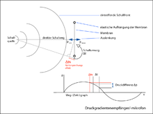
In contrast to a pressure microphone, the microphone capsule of a pressure gradient microphone (microphone with pressure gradient characteristics) is open at the back – the membrane is accessible to the sound from all sides. This microphone design is also scientifically referred to as a pressure gradient receiver or rapid receiver .
Since the sound also reaches the back of the membrane, it does not follow the absolute sound pressure, as is the case with the pressure receiver, but the pressure gradient or the sound velocity . A typical example is the ribbon microphone.
The pressure difference arises because the sound has to travel around the membrane in order to also have an effect on the back. The time Δt required for this results in a "pressure difference" (a pressure gradient).
- Δp = p front - p rear
For a given Δt , the pressure gradient is higher, the faster the change in sound pressure occurs. The resulting pressure gradient Δp decreases accordingly towards low frequencies. See: acoustic short circuit .
If a signal hits the membrane exactly from the side (90°), there is no pressure difference and therefore no membrane movement. When sound is applied to the back of the membrane, the polarity of the microphone signal is reversed (voltage inverted).
In the described symmetrical basic design, the directional characteristic is that of a figure eight. The design of the microphone also allows other directional characteristics that lie between omnidirectional and figure-8 to be implemented, such as the wide cardioid, cardioid, supercardioid and hypercardioid.
All directional characteristics apart from the omni (pressure microphone) can also only be realized with pressure gradient microphones.
Boundary Microphone
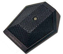
The term “ boundary layer ” or “ pressure zone microphone ” describes a microphone design with regard to its acoustic functionality. It is a special case because the microphone body is a conceptual part of the acoustic design.
The microphone body is a plate on which a pressure microphone capsule is usually embedded flush with the membrane surface. Its directional characteristic thus results in a hemisphere. The converters are usually designed as capacitors or electrets. This design was developed to take advantage of the advantageous acoustic properties that occur on sound-reflecting surfaces without impairing the sound field itself. The microphone is placed on a large, sound-reflecting surface, e.g. B. on the floor or a table placed. In this way, it receives the maximum sound pressure without overlapping room sound components, which leads to a balanced frequency response and a good acoustic impression of the room:
- There are no disturbing reflections on reverberant surfaces, since they are created here in the first place.
- In rooms, their natural resonances are less picked up by this microphone; By placing the microphone on a boundary surface, there are no sound-coloring comb filter effects that occur within the room. There are no timbre differences with moving sound sources.
- Room signals R are attenuated by 3 dB compared to the direct signals D, which means that direct sound is preferred.
directional microphones
shotgun microphone
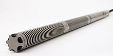
In a shotgun microphone , also known as an interference microphone , the microphone body is supplemented by a built- in interference tube .
A shotgun microphone has a pronounced lobe characteristic, which is caused by an interference tube that is built in front of a pressure gradient microphone and has lateral slits or bores and is open at the front. Depending on the tube length, this causes a significant increase in directivity from about 1 to 2 kHz. At lower frequencies, the directivity corresponds to that of the microphone capsule (cardioid or supercardioid characteristic).
Condenser or electret microphones are common as converters .
concave mirror microphone
Concave mirror microphones are often used to locate noise (particularly in aeroacoustic wind tunnels with an open measuring section) . Road vehicles or aircraft are usually examined.
Among other things, for bird watching microphones are used in the focus of a parabolic mirror as a directional microphone. Depending on the size of the mirror, the directivity only occurs at high frequencies (from around 1 kHz).
Two-way microphone
A two-way microphone has two separate sound pickup systems for low and high frequencies, with a cut-off frequency of 500 Hz, for example. These can be optimized separately in order to achieve an even frequency response for the entire system over a large frequency range and the effect of overemphasizing the low frequencies to be avoided if the distance to the speaker is too short. Such microphones are used, for example, in webcams , surveillance cameras and notebooks .
microphone signal
The AC voltage resulting from the sound conversion, the microphone signal, is characterized by the following parameters:
frequency response
The frequency response of a microphone results from its acoustic design, the microphone tuning and the converter principle. The smaller and the lighter the diaphragm (and possibly the plunger coil), the fewer natural resonances it has in the audible frequency band (20 Hz to 20 kHz). The less it resonates itself , the more undistorted it reproduces the sound. In the case of the pressure gradient microphone, for example, the acoustic design limits the low frequencies; In addition, the frequency response of all microphones depends on the acoustic irradiation angle (directional characteristic, pressure accumulation effect) and, in the case of pressure gradient microphones, on the distance from the sound source ( proximity effect ).
sensitivity
Microphones convert sound pressure into AC voltage . The field transmission factor is measured in millivolts per pascal (mV/Pa), which increases approximately proportionally with the membrane size. With electret microphones, for example, small 1/4 inch capsules have 5 to 10 mV/Pa, 1/2 inch capsules 30 to 50 mV/Pa, 1 inch capsules reach up to 100 mV/Pa.
rush
The smaller a capsule, the more susceptible it is to noise due to the low transmission factor. However, the cause of the noise is not the microphone membrane, but the electrical internal resistance of the capsule. In the case of dynamic microphones, for example, this is the resistance of the plunger coil, and in the case of electret microphones it is the load resistance. The higher the internal resistance, the more hisses the microphone, but the higher the output voltage is usually. Compared to moving coil microphones, electret capsules have a terminating resistance that is at least ten times higher and therefore at least √10 times (√10 ≈ 3) higher noise – but they also deliver significantly higher signal voltages.
impedance
Impedance is the electrical output resistance of the microphone to AC voltage in the audio signal range . While dynamic microphones often have impedances of around 600 Ω, condenser capsules have a very high impedance, but since they require a working resistance, this is the only impedance that appears to the outside (with electret microphones in the range between 1 and 5 kΩ). The higher the resistance of the microphone output, the greater the cable capacitance of the connecting cable becomes noticeable: High frequencies are dampened by long cables.
distortion factor
The distortion factor indicates the proportion of non-linear signal distortions in the useful signal as a percentage. With dynamic microphones, the distortion factor is low, non-linear distortions usually only occur at very high, irrelevant sound levels . The non-linear relationship between the diaphragm deflection and the voltage emitted distorts the signal in electret and condenser microphones in a non-linear manner above certain levels.
Electromagnetic susceptibility, hum
The most common hum interference is caused by ground loops (also called ground loops). Thus, it is usually not the microphone itself that is responsible for such interference, but rather the cable and the type of connection. These can be eliminated by differential (symmetrical) wiring or ground lines routed separately from the shielding. The sensitivity to interference increases with the length of the cable. Good shielding of the cable can eliminate the electrical interference, but symmetrical cables are insensitive to magnetic interference anyway.
Microphone cables sometimes have a microphonic effect , they are sensitive to impact noise and movement if their braiding or shielding generates changing contact resistances when moving. Low microphony is a quality criterion for microphone cables.
Digital microphone interface
The AES42 standard defines a digital interface for microphones that directly generate a digital audio stream. The processing chain impedance converter - microphone preamplifier - A/D converter is integrated in the microphone housing. The connection is made using an XLR connector, and the electronics are supplied with power via phantom power (Digital Phantom Power (DPP), 10 V, max. 250 mA). Such microphones can be remotely controlled by modulating the phantom voltage, for example to adjust attenuation or directional characteristics.
connection standards
- Balanced signal routing : mono signal, three wires: ground, positive signal pin "Hot", negative signal pin "Cold"
- Unbalanced signal routing: mono signal, two wires: ground, signal
- Unbalanced signal routing: stereo signal, three wires: ground, left signal, right signal
The symmetrical signal transmission is less susceptible to interference signals, especially with long lines.
Overview of common audio connectors: audio plugs

|

|

|

|
|
| standard |
XLR cannon connector, 3-pin + housing ground also 5-pin |
NAB 6.35 mm jack plug , 3-pin |
NAB 3.5 mm jack plug , 3-pin |
Large / small Tuchel connector , 3-pin + housing ground; also: 5-pol |
|---|---|---|---|---|
| application | Analog mono microphone, AES42 digital microphone signal, studio and stage |
Mono microphone, stereo microphone, home recording |
Stereo microphone, home recording |
Mono microphone, old standard lapel microphones |
| occupancy | Pin1 = Ground Pin2 = Hot Pin3 = Cold Housing = Shield |
Tip = Hot / Left Ring = Cold / Right Ground = Ground, Shield |
Tip = Left Ring = Right Ground = Ground |
Pin1 = Hot Pin2 = Cold (Small Ground) Pin3 = Ground (Small Cold) |
| cable | three-wire, shielded | three-wire, shielded | three-wire, shielded | three-wire, shielded |
| other applications |
Stereo signals Line signals digital audio ( AES/EBU ) Loudspeaker signals DMX (lighting technology) |
Stereo signals Line signals Loudspeaker signals Insert signals (recording studio) |
Headphone signals line signals remote control |
Microphone signals Loudspeaker signals Stereo signals Line IN/OUT |
These connection standards are the most common today. Some older microphones have a DIN or Tuchel connector . Occasionally there is also the "small-Tuchel" - especially with compact clip-on microphones with a separate radio transmitter.
The following applies to all microphones: The "male" on the microphone plug emits the signal and the "female" on the cable coupling accepts the signal.
Simple microphones are unbalanced and only have a coaxial cable (2 lines) as a connection line. This is also the case with electret microphones with tone wire feed - they work on the PC / on the sound card by using the feed voltage provided at these microphone inputs (usually 5 V) and working on the source resistance (a few kiloohms) of this voltage.
wireless microphones
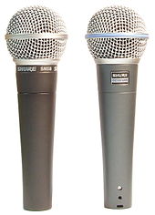
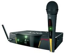
Wireless microphones are used wherever a cable connection is disadvantageous for technical, practical or optical reasons. For example, dynamic vocal microphones with an integrated transmitter (image) can be found on stages . Electret clip-on microphones or headband microphones (also called neckband microphones or headsets ) with a separate battery-powered radio transmitter (bodypack) are often used in television productions or in musical performances .
Disadvantages of radio transmission are above all a high purchase price and higher operating costs ( battery operation ).
In Europe, radio microphones usually transmit the useful signal frequency- modulated (FM) on the registration -free frequency band around 433 or above 862 MHz, the range is between 100 and 250 m. Which frequency bands may be used depends on the regulations in the respective country. In Germany there are also general assignments in the range from 790 to 862 MHz, which, however , expired in 2015 due to the digital dividend . In February 2011, the frequency range from 823 to 832 MHz, known as the duplex center gap (also duplex gap or center gap ), was allocated for wireless microphone use. This assignment is limited until December 31, 2021. In April 2020, the frequencies 470 to 608 and 614 to 694 MHz in a channel grid of 25 kHz were assigned general assignments until December 31, 2030, which means that the fees for the approximately 18,000 individual assignments on these frequencies to date have been paid omitted. Signal dropouts due to superimposition of the radio waves are avoided in professional transmission systems by using double reception technology ( antenna diversity , English true diversity ). A compander system consisting of a compressor on the transmitter side and an expander on the receiver side is used to increase the system dynamics; this achieves a signal-to-noise ratio of up to 110 dB. Some models transmit the signals digitally (then mostly in the 2.4 GHz ISM band). The digital systems are less sensitive to HF interference: With the modulation methods FSK or PSK , the frequency or the phase position of the signal can be recognized and reproduced despite HF noise.
Kate Bush is considered the first artist to have a wireless microphone headset built for use in music. For her 1979 Tour of Life tour , she had a compact microphone connected to a self-made construction of wire coat hangers , so that she did not have to use a hand microphone and had her hands free to dance her rehearsed choreography of expression dance on the concert stage while singing with a microphone at the same time . Her idea was later adopted by other artists such as Madonna or Peter Gabriel and used in performances.
application
The use of microphones is referred to as miking . Depending on the application, it is optimized according to technical, tonal and economic aspects. Various microphone stands are used for positioning.

Application-related designs
Depending on the application, microphones can also be categorized:
- according to the size of the membrane (small membrane/large membrane, the limit is 1 inch),
- according to the directional characteristic (see acoustic design)
- according to the external design:
- hand microphone
- Clamp, clip-on or lavalier microphone (lavalier microphones are usually condenser microphones and require phantom power).
- Announcement microphone with talk button, stationary use with a stand and " gooseneck " or as a hand microphone, e.g. B. for two-way radios
- as an integral part of devices such as headsets , telephones, hearing aids .
- after use:
- Speaker microphones are microphones that are specially optimized for speech in terms of characteristics and volume. These usually have an integrated cage for pop protection and a strong forward directional sensitivity.
Special designs:
They are pure solid -state vibration converters and therefore technically pick-ups and not microphones
A still very recent development (as of 2020) are membrane-free microphones that record air vibrations using optical methods. Due to their very high bandwidth, these microphones are particularly suitable for high-frequency ultrasound recordings.
multi-channel microphone systems
Two microphones together form a microphone system for stereo recordings , which capture a very specific recording area for the direction of the auditory event on the full stereo speaker basis. There are a number of stereo miking methods based on psychoacoustic effects:
- runtime stereophony
- intensity stereophony
-
equivalent stereophony
- ORTF stereo system
- NOS stereo system
- Decca Tree stereo system
- Binaural stereophony
surround sound
A special feature is the surround sound miking for recording particularly spatial 5.1 surround sound signals. Such systems are used in cinemas and orchestras. See also surround stereophony .
spot microphones
With all methods (stereo or surround), so-called spot microphones are set up in complicated recording situations in order to emphasize quiet voices a little more. Their level is mixed weakly with the actual main signal.
measuring technology
Acoustic measurement technology uses microphones with omnidirectional characteristics and a frequency response that is as linear as possible. A special application is the localization of sound sources using microphone arrays .
Microphone Accessories
Windscreen (popscreen)
A wind or pop screen protects microphones from air currents that occur when speaking or outdoors and cause rumbling, rumbling, "popping" (especially with plosives such as "B" or "P") background noise. Sometimes the noises are so loud that they overdrive the following amplifier and a real bang is created. Pressure transducers are less susceptible than pressure gradient transducers. Foam or fur covers ( jargon : windjammer , fur , zwelch , dead cat , dog , poodle or Puschel ) are used, as well as pop screens in recording studios. Many microphones have a permanently installed basket made of metal and gauze mesh to protect the membrane , which also keeps wind out to a limited extent. In the case of studio microphones, the pop filter also serves to keep the moisture and condensation that occurs when speaking and singing away from the sensitive condenser membrane.
microphone spider
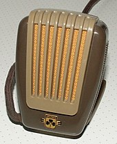
In order to decouple rumbling or clattering in the audio signal caused by vibrations ( structure- borne noise ) from the microphone, studio microphones are hung on a tripod in an elastic suspension, the spider . Spiders consist of a holder in which the microphone can vibrate freely by means of a rubber band stretched in a zigzag. Carbon microphones are particularly sensitive to vibration, which is why you often see speaker microphones outside the studio in elastic mounts on old photos. Vocal microphones usually have a microphone capsule bearing with elastomeric foams to decouple handling noises .
See also
literature
- Martin Schneider: Microphones . In: Stefan Weinzierl (ed.): Handbook of audio technology , Springer Verlag, Berlin, 2008, ISBN 978-3-540-34300-4
- Thomas Görne: Microphones in theory and practice. Elektor, Aachen 1994. ISBN 3-928051-76-8
- Michael Dickreiter, Volker Dittel, Wolfgang Hoeg, Martin Wöhr (eds.): Handbook of recording studio technology . 8th revised and expanded edition, 2 volumes. Walter de Gruyter, Berlin/Boston 2014, ISBN 978-3-11-028978-7 or (e) ISBN 978-3-11-031650-6 .
- Thomas Görne: sound engineering. Hanser, Leipzig 2006, ISBN 3-446-40198-9 .
- Gerhart Boré, Stephan Peus: Microphones. Working method and exemplary embodiments . (PDF) Company publication, Georg Neumann GmbH, 4th edition, Berlin 1999.
- Andreas Ederhof: The microphone book. 2nd Edition. Carstensen, Munich 2006, ISBN 3-910098-28-2 (with accompanying CD)
- Norbert Pawera: Microphone practice. Tips and tricks for stage and studio. 5th edition. PPV Media, Bergkirchen, ISBN 3-932275-54-3 .
- Anselm Rößler: Neumann, the Microphone Company. PPV Media, Bergkirchen 2003, ISBN 3-932275-68-3 .
- Matthias Thalheim: Dramaturgically staging consequences of artificial head stereophony in radio drama productions , diploma thesis, Humboldt University of Berlin 1985, Section Cultural Studies and Aesthetics, Theater Studies, Neoepubli Verlag Berlin 2016, ISBN 9783737597814
- Cathy van Eck: Between Air and Electricity. Microphones and Loudspeakers as Musical Instruments. Bloomsbury Academic, New York 2017. ISBN 978-1-5013-2760-5
web links
- Pure microphone sound: audio samples of professional vocal microphones – without effects
- Jörg Wuttke: Microphone attachments . ingwu.de
- Microphone sensitivity dB re 1 V/Pa and transmission factor mV/Pa
- Historical microphones, with sound examples
- Portraits of many classic microphones, excellent photos
- Nice photos - Vintage Microphones
- All microphone polar patterns and other parameters (PDF; 314 kB)
- Collection of modern and historical microphones
- Frequency allocations for radio microphones in Germany
itemizations
- ↑ Patent US174465A : Improvement in Telegraphy. Filed February 14, 1876 , published March 7, 1876 , Inventor: Alexander Graham Bell.
- ↑ Announcing the Invention of the Telephone. US Congress
- ↑ a b Joachim-Felix Leonhard, Armin Burkhardt, Gerold Ungeheuer, Herbert Ernst Wiegand, Hugo Steger, Klaus Brinker : Media Studies , Part 2. Walter de Gruyter, Berlin 2001, ISBN 3-11-016326-8 , p. 1255
- ↑ ECS: Calendar of Scientific Pioneers . In: Nature , 106, January 13, 1921, pp. 650f.
- ↑ a b Patent US3118022A : Electroacoustic transducer. Filed May 22, 1962 , published January 14, 1964 , Applicant: Bell Telephone Labor Inc, Inventors: Gerhard M. Sessler, James E. West.
- ↑ Will Hay: My Friend Mike . In: BBC Hand Book 1929, p. 185 f. translated from English
- ↑ Gerhart Boré, Stephan Peus: Gerhart Boré, Stephan Peus: Microphones. July 20, 2012 in the Internet Archive - (PDF) 4th edition. Fa. Neumann, Berlin 1999 (company publication). ( Memento from July 20, 2012 in the Internet Archive ) (PDF) 4th edition. Fa. Neumann, Berlin 1999 (company publication).
- ↑ Michael Dickreiter: Handbook of recording studio technology. 6th edition 1997, vol. 1, p. 182.
- ↑ Thomas Görne: Microphones in theory and practice. 2nd edition 1996, p. 87.
- ↑ Gerhart Boré, Stephan Peus: Replacement circuit for a carbon microphone - December 24, 2008 - ( Memento from December 24, 2008 in the Internet Archive ) - Neumann company
- ↑ Speaking capsule with electret microphone - December 23, 2008 ( Memento from December 23, 2008 in the Internet Archive ) formica.nusseis.de
- ↑ Thomas Görne: Microphones in theory and practice. 2nd Edition. 1996, p. 59.
- ↑ Michael Dickreiter: Handbook of recording studio technology. 6th edition. 1997, Vol. 1, p. 160.
- ↑ Michael Dickreiter: Handbook of recording studio technology. 6th edition. 1997, Vol. 1, p. 159.
- ↑ EBS : Microphone directional characteristics and other parameters – pdf Sengpielaudio
- ↑ EBS : Difference between hypercardioid and supercardioid – pdf - Sengpiel-Audio
- ↑ Connection of the directional characteristics (PDF; 79 kB) - EBS
- ↑ Michael Dickreiter: Handbook of recording studio technology. 6th edition. 1997, Vol. 1, pp. 146, 161.
- ↑ Thomas Görne: Microphones in theory and practice. 2nd Edition. 1996, pp. 167ff.
- ↑ Thomas Görne: Microphones in theory and practice. 2nd Edition. 1996, p. 39.
- ↑ Thomas Görne: Microphones in theory and practice. 2nd Edition. 1996, p. 41ff.
- ↑ Michael Dickreiter: Handbook of recording studio technology. 6th edition. 1997, Vol. 1, p. 164.
- ↑ AKG two-way microphones. Retrieved 11 June 2021 . (scan of an older data sheet)
- ↑ Michael Möser: Measurement technology of acoustics , 2009, ISBN 978-3540680864 , page 42, online: Two- way microphone D 222. In: Google Books. Retrieved 11 June 2021 .
- ↑ shure.de ( Memento from December 3, 2011 in the Internet Archive ) (PDF)
- ↑ General allocation of frequencies for wireless microphones. Disposition 34/2020. Bundesnetzagentur , April 8, 2020, retrieved May 21, 2020 .
- ↑ Maurice Sebastian Schill: Wireless microphones and their future , 2017.
- ↑ Claire Laborey (director): Kate Bush - Loudly voiced and eccentric. In: ARTE France Documentary - Culture and Pop > Pop culture . 2019, retrieved September 18, 2019 .
- ↑ Nature https://doi.org/10.1038/nphoton.2016.95
- ↑ Surround sound microphones - Schöps company ( Memento from September 28, 2007 in the Internet Archive ) (PDF; 1.5 MB)
- ↑ Stefan Weinzierl: Recording procedure. 2008, retrieved in 2020 .

