
speaker

Loudspeakers ( ) are sound converters that convert a (mostly electrical) input signal into mechanical vibrations that can be perceived as sound .
They are mostly used to generate sound to reproduce speech and music for humans with a typical working range at frequencies from 20 to 50 Hz up to 20 kHz. Special designs generate sonar signals under water or ultrasound (for animals or for ultrasonic cleaning). In the 1970s there were ultrasonic remote controls. Even simple distance measuring devices work with ultrasound.
The size varies between very small shapes, which are used for example in in-ear headphones , to columns several meters high for sound reinforcement at large concerts.
The term loudspeaker is used inconsistently both for the individual "loudspeaker chassis" or "loudspeaker driver" and for the overall construction of the sound transducer built into a housing, which is also referred to as a loudspeaker box.
The chassis in turn only includes the immovable parts of a loudspeaker in the narrower sense, while a driver often only refers to the sound-converting part of a horn loudspeaker ; confusion can easily occur here.
Speakers that sit directly on the ears are known as headphones .
history

The development of the loudspeaker is directly linked to the invention of the telephone and began in 1860 with the first public demonstration of a telephone set by Antonio Meucci . A year later, Philipp Reis presented his phone, which was later further developed by Alexander Graham Bell .
After the phonograph registered for a patent by Thomas Alva Edison in 1877 , Emil Berliner presented his gramophone in 1887 . Its distinctive horn, however, was not yet a loudspeaker in the sense of a "transducer" in that it merely emits the mechanical vibrations of the needle through an acoustic horn .
Werner von Siemens received the patent for an electrodynamic loudspeaker as early as 1878 ; his bad luck, however, was the lack of suitable amplifiers . Sir Oliver Lodge is considered to be the founder of modern loudspeakers . The first electrodynamically powered loudspeaker was presented to the public at the Berlin radio exhibition in 1925. In the same year Edward Kellog and Chester Rice from the American company Western Electric developed the dynamic moving coil loudspeaker, as it is in principle still used in most sound radiating systems today.
In addition to the continuous optimization of the materials used, the recording of the individual physical parameters made it possible to improve the classic loudspeaker in a targeted manner - especially taking into account its interactions with the respective housing. At the same time, new forms of converting electrical impulses into sound were developed, including vibrating air plasma .
Working principle

General
In most cases, a loudspeaker consists of three component groups: the membrane, the drive unit and their connecting elements. In the standard model of the so-called moving coil loudspeaker , the membrane is set in motion by a centrally mounted voice coil ; In addition to the coil, the drive includes a magnet in whose field it oscillates. A basket connects the magnet with a bead and a centering spider , which in turn guide the membrane.
Depending on the intended use, the required volume , the frequency range, the amount of space and the desired signal fidelity determine how the converter is designed in each case: Loudspeakers for announcements at airports have completely different requirements than players - earphones or ultrasonic cleaners .
In HiFi loudspeaker boxes, several frequency-specific optimized converters are used that are selectively controlled via loudspeaker crossovers in order to cover the entire listening spectrum. Loudspeakers can be described in their lower working area by their Thiele-Small parameters , making the complex interplay of their components mathematically understandable.
membrane
Depending on the design and frequency, the membrane moves in a piston or wave shape. While bending wave converters, for example, use the deformation effect, partial vibrations represent undesirable interference components in most loudspeakers.
To increase their rigidity, centrally driven diaphragms can be built in the shape of a funnel (which gives the usual cone loudspeakers their appearance) and the most stable material possible. Hard materials such as aluminum or ceramics, however, have pronounced natural resonances , while plastics such as polypropylene have good internal damping, but their precision and efficiency are weak. A wide variety of mixtures and layers are used today; Paper , which has been used for speaker cones for decades, continues to deliver the best results.
To avoid partial vibrations, the membrane can also be driven over as wide a surface as possible. This principle is followed, for example, by magnetostats in which the voice coil - applied in the form of a film - is distributed over the entire membrane surface; their material may then be correspondingly thin (read: light and thus pulse-fast). However, the deflection of such surfaces is limited by the surrounding magnetic bars.
The lower the tone, i.e. the lower the frequency, the more air a membrane has to move for the same volume. This volume results from the total area and deflection capacity . Larger membranes are correspondingly heavier and more sluggish ; in addition, the bundling of sound increases. A larger deflection in turn causes a higher mechanical load and requires a more complex drive.
drive
The drive parameters depend both on the size of the coil (diameter and winding height) and on the strength and range of the magnetic field. The coil internal resistance (depending on the conductivity of its material), the distance between the coil and the magnet and any losses due to eddy currents (depending on the - undesirable - conductivity of the coil carrier) are also decisive .
By using new materials such as neodymium , much stronger magnets can be produced today than at the beginning of loudspeaker development. Aside from the obvious advantages, a more powerful drive alone does not necessarily "improve" the loudspeaker; In the case of a built-in woofer, the required housing volume is reduced, but the lower limit frequency increases at the same time .
In piezo speakers omitted coil and magnet: The signal is applied to a disc of piezoelectric applied material, which is directly connected to the membrane. Electrostats, in turn, work with a stepped-up signal that acts via stators on a foil membrane that is under constant voltage; In the case of the plasma loudspeaker , an ionized gas is caused to vibrate with a high-voltage field.
Basics theory
In the lower working range around the resonance frequency, speakers that work as a driven mass-spring system can be described by the Thiele-Small parameters .
Similar to electric current, which can be described by the electric current strength and the electric voltage, with sound waves there is the sound velocity and the sound (change) pressure. The speed of sound describes the speed with which the air molecules are moved by the sound, sound pressure describes the resulting pressure. Sound radiation of a membrane to the surrounding air is a very inefficient thing due to the low acoustic impedance of air, which drops further to 0 at low frequencies, at higher frequencies it increases with a few overshoots up to a limit value specified by the shape and size of the membrane . In the classic problem of the piston radiator in an infinite baffle in an infinitely large space on all sides, the radiation resistance is proportional to the frequency up to the limit value. This should result in a high-pitched sound. With almost all radiators, however, the mechanical force applied is constant for higher frequencies and thus, according to Newton, also the acceleration. This means that the speed is inversely proportional to the frequency. This precisely compensates for the increase in radiation resistance. With most radiators there is a range in which the emitted power is independent of the frequency, without further action, and this is consequently chosen as the main working range.
The example with the infinite baffle shows that an analytical mathematical treatment is only possible in simple model cases. Several membranes or resonators interact with each other and with the structural elements of rooms. Among other things, this changes the radiation resistance. The radiation resistance can be thought of as the combined reaction of the radiation field on the radiator.
In the case of direct emitters, which only consist of membranes, the forces with which the radiation field acts back on the membrane are negligible compared to the driving force, the inertia and the elastic spring forces. The movement of the membrane is practically independent of the barometric constant air pressure, right up to the vacuum. Electrical and mechanical measurements on the chassis in the free field are therefore comparable to those in the reverberation room. The calculation of the interconnection of several membranes to form a field can therefore be carried out by simple, reaction-free superimposition of the individual characteristics. In this case one speaks of a mismatch with a correspondingly low efficiency.
The use of acoustic resonators or impedance transformers, for example horns , changes the coupling of the membrane to the radiation field very drastically in a narrow or broadband manner. The forces of the radiation field on the membrane are no longer negligible. In this case the interconnection is not retroactive and the other simplifications no longer apply. In this case, one speaks of a power adjustment with good efficiency.
Designs

Schematic of cone loudspeaker, lateral section ("cover cap" = dust cover )
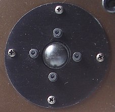
3/4 ″ dome tweeter with 19 mm voice coil

Loudspeaker basket with membrane removed


Moving coil speaker
This principle is still the most common type of construction. The name comes from the fact that a coil vibrates in the field of a surrounding magnet, so it “dips” into it. Depending on the intended use, such speakers can look completely different. In the home hi-fi area, the range of converters extends from 12 ″ woofers with a diaphragm diameter of a good 30 centimeters to 3/4 ″ tweeters with a diaphragm diameter of just under 2 cm.
From a technical point of view, they are dynamic loudspeakers , i.e. they are electrodynamically driven. The movement is triggered by a centrally mounted coil; it is wound on a cylindrical support which in turn is attached to the membrane . If an electrical signal is passed through the coil, the Lorentz force (interaction with the field of the surrounding magnet) exerts a force on the membrane, which causes it to vibrate. The coil and membrane move back and forth in the magnetic field, perpendicular to the course of the field. A centering spider and the bead ensure that the diaphragm is returned to its rest position and that the voice coil is centered.
The membrane, voice coil, bead and spider are the moving parts, while the magnet and loudspeaker frame are fixed. The basket holds the magnet and the membrane via a spider and bead and its outer edge is used to mount the loudspeaker. The bead is usually made airtight and then also contributes to the sound radiation. The centering spider and basket, on the other hand, should offer as little resistance as possible to the rearward exchange of air.
The deeper the sound to be reproduced, the greater the volume of air moved. Subwoofers therefore usually have large diaphragms and wide excursions. For reasons of stability, large diaphragms are made cone-shaped and driven in the center by the voice coil. Tweeters must be able to follow faster impulses. Small membranes also counteract the increasing concentration of sound at higher frequencies. For this reason, tweeters usually have a dome-shaped membrane with the voice coil attached to the outer edge.
Since the membrane basically works as an acoustic dipole - that is, it emits sound both forwards and backwards - an acoustic short circuit can occur at low frequencies . In order to avoid the mutual cancellation of the sound components emitted from the front and rear, broadband and bass loudspeakers are usually built into housings .
The most unadulterated reproduction of the original signal is expressed in a frequency response that is as straight as possible . The components of a loudspeaker together with the moving air mass form a complex mass-spring system. The mass and rigidity of the membrane are just as important as the flexibility of the bead and spider and the properties of the coil and magnet.
Since Albert Thiele and Richard Small specified the Thiele Small parameters named after them, it has been possible to predict the properties of loudspeakers, including the housing, as early as the design phase.

middle: loudspeaker with underhang coil
below: hybrid solution

Coil and stator magnet
Dynamic loudspeakers (on the one hand moving coil loudspeakers as well as so-called magnetostats) use the Lorentz force as a force between a stator magnet and a current-carrying conductor (designed as a wound coil or as conductor tracks attached to the membrane).
The Lorentz force as the driving force is

This means that there must always be the same coil length in the magnetic field. This can be achieved using the following three arrangements:

Loudspeaker with overhang
coil : The coil is longer than the pole plate height. Only a (certain) part of the drive coil is used up to a certain limit deflection. Used for almost all loudspeakers that have to perform considerable deflections. The flux of the stator magnet is used completely, that of the coil only partially, since parts are outside of its magnetic field.
Loudspeaker with underhang
coil : The coil is shorter than the pole plate height. Up to a certain limit deflection, the drive coil is always completely between the pole plates. Use with almost all loudspeakers that only have to perform small deflections. The flux of the coil is used completely, that of the stator magnet only partially, since parts are not filled by a coil.
Hybrid solution:
Up to half the deflection of the voice coil height, half the voice coil is always between the two pole plates. The drive is complex, but has great symmetry, which reduces odd harmonics. Driving force and inductance have a value that is more independent of the driving current and deflection. The drive can be held by two spiders (not shown). Half of the flux of the stator magnet and the coil are used. However, the flux of the stator magnet is used twice, but it also has to overcome two air gaps.
membrane
The geometric surfaces of today's dynamic loudspeaker membranes are curved in all directions to avoid buckling vibrations (so-called non-developable surfaces):


Dome loudspeaker: the
diaphragm and drive coil (mostly) have the same diameter. This principle is mainly used with tweeters, sometimes also with mid-range speakers. Usual sizes are 19 mm to 28 mm for tweeters, 50 mm to 76 mm for mid-range speakers. The dome is usually convex (raised dome), but sometimes also concave (inverse dome). Working ranges start at around 3 kHz for 19 mm tweeters and at 450 Hz for 76 mm mid-range loudspeakers (values are guidelines).
Cone loudspeaker:
The diaphragm has a much larger diameter than the drive coil and is concave. This principle is mainly used for woofers and mid-range speakers. Usual sizes start at 10 cm and end at 45 cm. Woofers and subwoofers tend to have larger diameters, mid-range loudspeakers, but also woofers for smaller boxes, tend to be smaller.
Flat membranes:
Another possibility is flat membranes. These are either driven over the entire surface (e.g. in the case of flat-panel loudspeakers) or, through a clever design, dampened bending vibrations are used to radiate sound.
Mechanical construction
In the classic cone loudspeaker, the magnet sits at the rear end of the so-called basket or chassis , which has the shape of a bowl that is pierced by several large openings to allow the sound to pass unhindered. The edge of the membrane is elastically suspended from the front opening of the basket by a circumferential bead . The edge is usually widened to form a flange to which the loudspeaker can be attached (e.g. in a loudspeaker box ). The narrow end of the conical membrane carries the voice coil and is guided by a spider so that the coil moves without contact in the narrow air gap of the magnet.
The rigidity of the chassis can influence the sound behavior of the loudspeaker at low frequencies. High-quality woofers are made of solid die-cast to avoid resonances in the unfavorable range.
Too wide webs, as well as missing openings between the centering and magnet, hinder the membrane movement, because the air cannot circulate freely there. The more impermeable the spider, the more it slows down the vibrations.
The bead not only influences the properties of the loudspeaker through its relative flexibility (see Thiele-Small parameters ), but also partly contributes to the sound radiation itself. In the case of ring radiators (a special case of the dome tweeters ), for example, the function of the concentric membrane is performed solely by the beads.
Magnetostatic loudspeaker

Contrary to their name, magnetostatic loudspeakers are electrodynamic loudspeakers . They work on the same basic principle as moving coil loudspeakers. They are not to be confused with electrostatic loudspeakers, which use a different drive principle and also (have to) be controlled completely differently.
Here the voice coil is not mounted on a separate carrier, but attached directly to the membrane (foil magnetostats) or left out entirely: With the classic "ribbon", the electrical signal acts on the membrane itself. The large-area drive and the weight saved - the The membrane does not need any rigidity and can therefore be extremely thin - ensure the best impulse fidelity and detail resolution.
However, the sound has to find its way between the surrounding magnets (here: magnetic bars). Their field strength in turn limits the deflection of the membrane, and as the area increases - if it is also to reproduce lower frequencies -, as with all membranes, bundling effects arise.
Magnetostatic loudspeakers are mainly used today in the high and mid-range.
Ribbon
Aluminum is usually used as the membrane material (around 10 µm, i.e. around aluminum foil ). The signal flows through the foil vertically and is located in the stator field of permanent magnets whose field lines run horizontally; the resulting Lorentz force moves the membrane back and forth and leads to sound radiation - similar to all dynamic transducers.
As a technical hurdles, however, on the one hand, the extreme sensitivity of the material (irreversible overstretching at a high volume) prove to it and on the other hand, the low impedance : The minimum internal resistance of the film would any normal amplifier burn or be switched off, which is why these speakers with an additional transmitter to be equipped have to.
Ribbons are practically only used as tweeters. Ribbon tweeters are used today in particular in hi-fi systems in the high-end segment, mostly as hand-made high and mid-range coaxial speakers. They cost a four- to six-digit amount.
Foil magnetostat
A plastic film acts as the membrane to which a conductor track (usually made of aluminum) is applied, which in turn represents the voice coil.
One advantage over the classic ribbon is that the impedance is in amplifier-friendly regions (4–8 ohms ), which is why such loudspeakers can be connected directly without a transformer. Various tough - i.e. resilient - plastics are available as membrane material. Foil magnetostats can therefore be built much larger, which extends their range of application towards lower frequencies.
The bundling effect of large membranes is often counteracted by a curved structure of the entire loudspeaker. However, it is not enough for a serious bass reproduction. Most magnetostat boxes therefore contain an additional moving coil transducer for bass reproduction.
Jet tweeter
The loudspeaker developed by Oskar Heil solves several problems:
- the limited deflectability: the membrane (including the attached drive coil) is folded like an accordion. Instead of moving back and forth between the magnetic bars, it moves through parallel contractions. The air is alternately sucked in and forced out by the opening and closing zigzag folds.
- The low resistance: Instead of a continuous film, the drive consists of a non-conductive film on which the drive coil is applied in a meandering manner.
In this way, with comparatively little membrane movement, a multiple of the sound pressure can be generated and a characteristic impedance of 4 to 8 ohms can be achieved, which makes the otherwise necessary transformer superfluous. On the other hand, the surrounding magnet rod groups have to be further apart than with other magnetostats, because the folded membrane takes up more space - and the much larger total area also makes it heavier. Air motion transformers are therefore only available as tweeters to this day.
Electrostat

Electrostats use the Coulomb force instead of the Lorentz force as a drive. A high control voltage is required instead of a large control current. Furthermore, this intrinsically highly non-linear force (k 2 = 100%) must be linearized by using a preload and the push-pull principle. In terms of design, this type of drive is almost always combined with flat-panel loudspeakers. The voltage is not fed to an electrode, but is always applied between electrodes. Different forms of control are possible.
Here the principle of the magnetostat is practically reversed. The signal is not applied to the membrane, but to the surrounding elements: two electrode grids (also called stators) that work in push-pull.
Electrostats (short: "ESL") use the electrostatic attraction. The tightly mounted membrane film is placed under a high constant voltage (between 1,000 and 5,000 volts ).
As far as problems with deflection or sound bundling are concerned at higher frequencies, electrostats are the same as their magnetostatic counterparts here as well as in their sonic advantages. However, a significantly higher technical effort has to be made - and they do not work without a separate power supply from the socket.
This type of construction was developed at a time when it was not yet possible to produce sufficiently strong permanent magnets, as are necessary for large-area magnetostats. Loudspeakers such as the legendary quad electrostat (1957) were the first transducers with a membrane membrane that covered almost the entire human hearing spectrum.
Piezo speakers

Piezo loudspeakers use the piezoelectric effect . A piezo crystal changes its thickness proportionally to the applied voltage. Piezo elements thus already work as direct sound-emitting transducers.
Because of the comparatively low volume, they can only be found as the sole sounder in small devices, such as buzzers . Where a higher level is required, the element is provided with a conical membrane, which in turn radiates into a horn.
Piezo speakers are hardly used at all in the hi-fi sector. Common crossovers fail because of their impedance curve , and the violent resonances of the transducers (mostly in the range of 1–5 kHz) then do not allow distortion-free playback. In fact, however, these problems can easily be avoided: after connecting a suitable resistor in parallel , their frequency spectrum can be filtered as usual.
In addition to the use of ultrasound to drive away insects or as a defense against marten , piezo loudspeakers are therefore also used as hi-fi converters; Above their resonance frequency they sound just as clean as high-quality dynamic tweeters.
Electromagnetic speaker

The construction principle comes from the early days of audio technology . Either an iron membrane is moved, which radiates the sound directly (see picture), or an iron rod enclosed by a coil oscillates in front of the air gap of a permanent magnet and is connected to a paper membrane.
Such converters (also functionally identical, magnetic microphones ) were used, for example, in military communication; They were also used in Morse headphones and telephone receivers .
Electromagnetic loudspeakers have hardly been used since the 1930s because of the inadequate reproduction quality (tinny sound, high distortion factor). They were still found in children's toys in the 1980s.
Plasma speakers

They are the only loudspeakers that transmit electrical signals directly in sound waves without going through solids such as voice coils or membranes. They generate an air plasma between two high-voltage electrodes, the field of which oscillates amplitude-modulated in the signal cycle, and thus use the property of air to expand when heated and to contract again when cooled.
Theoretically, the principle is almost perfect: plasma speakers work practically without delay, have no mechanical impairments such as inertia , material resonances or pre- / post-oscillation and deliver a linear frequency response well beyond the audible range.
Limitations of the ideal spherical radiation result inevitably from the components that generate the plasma and are more or less "in the way".
In practice there were initially problems with odor nuisance (due to the formation of ozone ), but this could be resolved. The main reason why plasma loudspeakers hardly play a role today are DIN standards , which, among other things, relate to electromagnetic compatibility : The rules prescribe shielding - for example by surrounding metal grids - which reduces many of the acoustic advantages of these transducers to absurdity .
To this day, plasma speakers are only used as tweeters.
Special forms
Horn drivers

Horn loudspeakers can be based on any transducer principle. Horn loudspeakers do not emit sound directly, but rather through an upstream horn. This increases efficiency by making the transition of the sound from a dense medium (membrane) into the thin medium (air) more continuous.
Horn drivers can also be combined with a pressure chamber, this represents a narrowing of the sound guide in front of the actual horn. Pressure chambers further increase the efficiency, but increase the distortion factor. The animated graphic shows a horn driver with an additional pressure chamber.
Horn drivers differ from other dynamic loudspeakers in that they are optimized for operation with a front-mounted horn. You therefore do not have a mounting ring to fix it in a baffle, but a (standardized) connection flange . Your basket consists of a largely closed shell that tapers in front of the membrane.
The obligatory horn attachment ensures a significant increase in efficiency, but also influences the frequency response and radiation behavior.
In the PA sector , sound guides and horn attachments are often used to increase efficiency. In HiFi practice, horn drivers are only offered for sound reproduction from the midrange upwards.
Bending wave converter

While the membrane of conical speakers should be as stiff as possible in order to ensure a piston-shaped movement, bending wave converters make use of their deformability: the waves spread out on the membrane, concentrically from the point of the voice coil, like on a surface of water.
For this, for example, the bead - more precisely: the suspension of the membrane on the outer edge - must be built differently; the edge ends with a wave impedance so that reflections are avoided. The suppression of unwanted partial vibrations is one of the greatest problems of such loudspeakers, along with the low sound output. On the other hand, they shine with their homogeneous reproduction and wide dispersion.
In addition to the well-known flat membranes developed by Josef Wilhelm Manger , other loudspeaker designs now also work according to this principle (see below, section “All-round radiators”).
Apart from borderline cases such as soundboards (here parts of a room wall are made to vibrate by exciters - see below, section “Other variants”), such flexible wave loudspeakers are quite expensive and are therefore mainly offered in the high-priced hi-fi segment.
Radial emitters

In order to counteract the bundling of sound, such structures emit at least horizontally (if possible) omnidirectionally. In most cases, however, this is done using housing elements, for example with the help of dispersion cones that are mounted in front of conventional converters. Intrinsically omnidirectional speakers are very rare.
So far, only plasma speakers (see below) have come close to the theoretical ideal of spherical radiation. Other special loudspeakers, such as those from German Physiks or MBL, offer circular radiation . The former use the "back" of an elongated conical membrane that works on the flexural wave principle ; with the latter, a lamellar ring is compressed in time with the signal .
Your advantage in HiFi playback is the even radiation pattern, which does not lock the listener to a point in the stereo triangle . On the other hand, room acoustic effects are amplified, which impairs the imaging precision: the sound components that are reflected by the room walls and have different transit times are superimposed on the room information already contained in the recording.
Omnidirectional loudspeakers are only used to reproduce the mid- and high-frequency ranges, since in practice conventional converters also emit lower frequencies in an approximately spherical shape.
Other variants
Subwoofers are specialized loudspeaker boxes for bass and deep bass which, together with satellite boxes, reproduce the full spectrum.
Exciter make a diaphragm-free vibration exciter a special form of the speaker is to be driven as normal hi converter of respective amplifiers, but need one. Solid medium as a "membrane" - that is, they must be fixed only on one object that they vibrate . In practice, they can be mounted behind wall panels, for example, so that parts of the room wall then act as "invisible loudspeakers". Such combinations work in principle as bending wave converters . Other types are screwed onto seating furniture instead of a subwoofer to complement the sound, where theygenerate structure-borne noise and thusamplify the listener's subjective bass sensationthrough low-frequency vibrations .
Ultrasonic transducers are used, among other things, for animal defense (see above, section "Piezo loudspeakers") or for measuring purposes (according to the runtime principle , see echo sounder and sonar ), and also for cleaning , material processing and in medicine (see sonography ). Using subharmonic oscillations , ultrasound can also be used to reproduce audible frequencies, but this principle is hardly practical.
So-called parabolic speakers, on the other hand, are not independent converters, but only use the bundling by mechanical reflectors. Examples of this are “sound showers” (used in the exhibition area for locally limited audio information) or - in a military context - sound cannons .
The term flat speaker, on the other hand, is used in so many different contexts that it means practically nothing. This can mean dynamic transducers with a straight instead of a cone-shaped membrane, as well as wall elements operated by exciter (see above) or loudspeakers that are mounted directly in a room wall instead of in boxes (whereby their reproduction characteristics roughly correspond to installation in an infinite baffle ).
Loudspeaker boxes
Speakers also be shortened as speaker referred. They contain one or more sound transducers or chassis and possibly a crossover network and other electronic components that are combined in a housing.
Depending on the number of built-in speakers, they are called one- way speakers , two-way speakers , etc. See loudspeaker box # Classification according to the number of paths
Passive loudspeakers are connected to a separate amplifier . Active speakers contain a built-in amplifier. See loudspeaker box # supply
Limits of sound reproduction
Contrary to popular opinion, reproduction errors caused purely by acoustics can very well be measured, and their effects on the listening experience can be assessed, provided that it does not concern the reception of the sound event by the human ear.
A basic requirement for good audio reproduction is that the loudspeaker systems are correctly connected electrically to a suitable audio amplifier with the lowest possible output impedance. The source, such as the CD player or record player , the audio amplifier and the loudspeaker as well as its acoustic adaptation to the speaker housing and the free propagation of sound have different influences on the playback quality. This topic is discussed controversially.
In addition to the recording by the ear, a listening experience also includes sensory perceptions of the vibrations of the body above the floor or the low-frequency sound. They can only be captured with full-body simulations. In addition, individual listening habits, preferences, the current state of mind of the listener and, ultimately, their hearing condition are taken into account to a large extent in the assessment of the listening experience.
Loudspeaker boxes also interact with the listening room in a variety of ways, which is why the room acoustics in combination with the loudspeaker system play an essential role in the listening result.
Linear rendering errors
Linear playback errors are level-independent errors. They occur at all sound levels. Furthermore, there are no frequencies that do not exist in the original. This last point is crucial for distinguishing between linear and non-linear errors. Mathematically, addition theorems can be used to show that new frequencies arise in the spectrum only in the case of non-linear errors.
Frequency response
Linear distortions are, for example, non-linearities in the amplitude frequency response, i.e. This means that different frequencies are reproduced at different levels by the loudspeaker despite the identical input signal level. Depending on the type and extent of these non-linearities, they lead to sound discoloration during playback (too loud bass, too few mids, etc.). Ideally, a loudspeaker should reproduce all frequencies in the audible range (20–20000 Hz) equally loudly. In practice, deviations of up to ± 0.5 dB are indistinguishable for the human ear, deviations of up to around ± 2 dB, provided they are only narrow-band, are not considered to be audibly disturbing. The broader this discoloration, the more likely it is to be audible and annoying. Increases in individual frequency bands are more audible and more annoying than decreases.
Linear frequency response is achieved with multi-way loudspeaker boxes or corresponding broadband converters. In addition to the loudspeaker, the listening room and box geometry as well as the loudspeaker attenuation by the amplifier and the insulation of the box have a major influence on the frequency response. Deviations in the frequency responses (pair deviations) of the loudspeakers involved lead to localization blurring and sound changes from moving sources. The latter is particularly annoying with video playback. This results in problems above all with so-called center loudspeakers, because these are usually designed and set up differently than the associated front loudspeakers.
The sensitivity is different:
- Errors in the front can be heard more clearly than in the back.
- The human ear is most sensitive to left-right deviations. Front-back or top-bottom defects are less noticeable to the human ear.
Deviations in the range of 250 Hz to 2 kHz can be determined from 0.5 dB, maximum differences of 0.25 dB should therefore be aimed for, but hardly achievable.
In addition to the discoloration on the ideal radiation axis of the loudspeaker (hearing axis), it is also decisive for the hearing impression how the sound is emitted away from this axis, because not all listeners can always be in the hearing axis. Ideally, a loudspeaker should reproduce all frequencies identically loud in every spatial direction, whereby only the overall level may deviate (even bundling of sound). In practice, however, this bundling is often heavily dependent on the frequency, particularly in the mid and high range, which should be avoided in the home area by stabilizing the radiation behavior ("constant directivity"). Dome tweeters are advantageous here, because they have a much better all-round radiation at high frequencies than membrane, funnel or horn speakers.
In outdoor areas, on the other hand, people are often interested in radiating high frequencies in a directed direction in a narrow solid angle in order to compensate for their greater air attenuation at greater distances. While nearby listeners are then outside the main radiation cone of the tweeter (e.g. horn loudspeaker), distant listeners are reached by the main cone and perceive high frequencies sufficiently loud. An alternative are additional high-frequency loudspeakers set up in the rear auditorium and directed at the rear audience. However, these must be activated with a time delay.
Reflections in the reverberation room cause very large level fluctuations that can be in the range of +10 dB to −40 dB. Particularly at higher frequencies, the superimposition of direct sound and multiple reflections results in extremely complicated spatial sound fields. When playing a sine wave, these level differences can be clearly perceived when walking around.
Phase response
One problem is interference between the various sound paths of multi-way loudspeaker boxes in the area of the crossover frequencies or several boxes that reproduce the same frequencies. This leads to location-dependent amplifications and cancellations of frequencies through constructive and destructive interference, which ultimately leads to location-dependent frequency response errors. However, you should note that such phenomena always occur in the reverberation room, even if only one loudspeaker is operated.
The human ear is relatively insensitive to phase shifts, such as those caused by an all-pass filter. However, there are cases in which phase differences are noticeable, for example in situations where two tones fall within the critical bandwidth. In this case, the sensory cells of the inner ear can detect differences with their one-way rectifying effect. Far more important than the phase rotations, however, are the resulting different group delays . In extreme cases, impulses are broken down into individual corrugations , a consonant like "t" then becomes something like "huii". The temporal resolution of the hearing with regard to the arrival of different stimuli at different frequency groups is very limited. Group delay differences of up to a few ms are therefore imperceptible. This means that several loudspeakers in one box are less likely to contribute to the falsifications, whereas the listening room or several boxes at different distances make a decisive contribution.
Impulse fidelity
Impulse fidelity is the term used to describe the ability of a loudspeaker to follow the course of a pulse-shaped signal with as few transients as possible. Essentially, these are low and medium frequencies that arise when resonant components (partial vibrations on the membrane, hard-hanging membrane as a whole, cavity resonances in the loudspeaker box and in the listening room) are excited to vibrate.

Sudden transients trigger movements in the loudspeaker membrane, which run outwards in waves. As a result, sound is still emitted, although the pulse has long since ended. As a rule, the edge is not terminated with the correct wave impedance , so the wave is reflected and extends the pulse further.
The impulse fidelity is determined not only by the loudspeaker quality (the softest possible suspension of a membrane that is as stiff as possible, high coupling factor or efficiency) and its installation (box geometry and good damping), but also by the lowest possible impedance feed of the voice coil. If the internal resistance of the amplifier output and the resistance of the loudspeaker connection lines (and a possible crossover network ) are too high overall, the loudspeaker carries out further undamped oscillations with its natural resonance that are not part of the music signal. However, the ear is able to interpret even a few individual oscillations of a damped oscillation as a short tone and to determine its pitch.
Bass reflex boxes in particular deliver poor impulse responses in the range of their lower limit frequency, as they function on the basis of the resonance of the spring-mass system, air volume in the box or air mass in the bass reflex tube.
In the realistic situation of a normal living room or even a room with even more reverberation (e.g. empty concert hall), however, the effects from reflections or cavity resonances can often result in greater and different effects on the impulse fidelity than those caused by the construction of the Speaker or the box. There are also differences in transit time, which are caused by reflections on different paths or several loudspeakers set up far away and which can also falsify the impulse response at high frequencies and make speech incomprehensible. Effects from multiple reflections are beyond the scope of this article. On the other hand, runtime effects resulting from playback with several loudspeakers set up at different distances from the listener can be avoided if the loudspeakers all radiate in one direction and they are controlled with a time delay according to their distance from the stage.
Nonlinear rendering errors
Non-linear reproduction errors are essentially level-dependent errors. The main cause is the non-linearity of the electromechanical motor consisting of the coil and magnet system. At high sound levels, the sound propagation in the air is also non-linear, which is typically noticeable in horn loudspeakers for large-scale sound reinforcement.
The non-linear distortions are usually specified as a frequency spectrum , because the hearing perceives the non-linearities largely in the same way. It is said that the non-linearity “generates additional frequencies” - different frequencies with different levels depending on the type and strength of the interference.

- Total harmonic distortion - Total harmonic distortion is the best known and easiest to measure nonlinear distortion. In the high frequency range (from around 1 kHz) the distortion factor is often below 1% even with thermal limit load. The reason is the very low membrane deflections at high frequencies. Such distortion factors are still perceptible, for example, with sine tones. The underlying non-linearity, however, is much more unpleasant noticeable through difference tones. At low frequencies, however, the deflection increases by orders of magnitude and leads to non-linear effects, among other things due to non-linear forces of the suspension or in particular due to the fact that the plunger coil partially leaves the air gap. In addition, there are parasitic vibrations within the membrane, which also lead to harmonics . In the picture on the right, this increase in the distortion factor towards low frequencies can be seen well by about ten times. In the case of very low tones, distortion factors often go unnoticed when playing music, but they are clearly evident with sinusoidal signals, since the harmonics are in the range of great hearing sensitivity. With professional, portable loudspeakers, the distortion components are far below 1% even at a working level of over 100 dB at a distance of one meter. Even expensive products for the end consumer, on the other hand, can already have audible distortions at room volume. The extent to which the auditory quality of a loudspeaker essentially depends on the various non-linearities is an open question, see among others the work of Geddes / Lee.
- Amplitude intermodulation - The same causes that cause harmonic distortion are, as can easily be seen mathematically, also in principle a reason for intermodulation. Many non-linear parts work together in a loudspeaker. It is therefore hardly possible to derive the intermodulation directly from the harmonic distortion. Representing the intermodulation is very difficult for the same reason.
On the other hand, this type of distortion is already perceived as annoying with lower proportions than with distortion . Professional systems achieve less than 1% difference and sum distortion at the usual working level. Consumer loudspeakers that are more prone to compromise generate more than 10% at their working level, depending on their size and frequency range.
- Frequency intermodulation - Because the membrane has to move to generate the sound, its position is constantly changing relative to the transmission medium. The constant change in position acts on the sound wave like a modulation of the phase, better known as the Doppler effect . The more broadband the loudspeaker or the higher the level control, the more pronounced it is. In particular, high frequencies that are generated by partial vibrations of the membrane are subject to the stroke of the bass tones. The loudspeaker then represents a sound source alternately approaching or moving away from the listener to the extent of the current membrane deflection. High frequencies experience a beat (i.e. detuning) in the rhythm of the lower frequencies that are subordinate to them, which results in roughness in the sound can make noticeable.
- Dynamic compression - Dynamic compression occurs when the loudspeaker approaches its dynamic range and is also due to the moving coil partially leaving the magnetic gap or the mechanical limitation of the deflection by the suspension.
Room acoustics
Smaller listening rooms interact with loudspeakers and produce coloration of the sound. There is interference between direct sound and reflected sound, which changes the sound. Only large (from a few thousand cubic meters) and well-designed rooms show slight discolouration of the sound.
For a specific point in space, the falsifications could be removed by inverse filtering. However, the problems a few centimeters away don't get better, but rather worse. It is thus clear that the sound field of a recording room can in no way be reproduced in the normal listening room and that optimizing the frequency response in the hypoechoic room is relatively uninteresting in the case of the normal listening room. These effects also occur with other sound sources, such as a speaker or a musical instrument instead of the loudspeaker. The falsifications are always present and are part of everyday experience, it is no coincidence that the hearing is insensitive to such disorders.
Correction techniques
Every sound transducer, i.e. the driver (s) including all elements of the housing or the sound guide (basically also the listening room) is a system with distributed parameters. The classic idea of an electromechanical system with concentrated parameters (masses, spring stiffness, oscillating circuit quality) can only give first clues for a simulation. The Thiele-Small parameters are also used for the calculation . Various correction techniques have been developed so that an optimization can be carried out with the parameters distributed in the system. These can be roughly differentiated into controls and regulations.
Damping due to low feed resistance

The simplest and most important measure is the exact control over the damping effect of the amplifier output. Because of the negative feedback, most power amplifiers are a control loop. If the instantaneous value of the output voltage falls or rises as a result of feedback from the loudspeaker, the negative feedback feeds the value back to that of the control signal. The amplifier output ideally represents a source impedance of zero for the loudspeaker.
In simplified terms, every dynamic loudspeaker is a damped spring-mass system that has a basic resonance and, due to the different vibration modes of the membrane, always also has partial vibrations at higher frequencies. As a result of the impedance changing in magnitude and phase, the oscillating loudspeaker loads the amplifier differently than an ohmic resistor. A dynamic loudspeaker always works like an electric generator . This is particularly important with weakly mechanically damped speakers in the area of their basic resonance. The voltage generated is often out of phase with the supply voltage. The voltage acting back on the amplifier is more or less short-circuited due to the usually very low internal resistance of the amplifier output, and the attenuation of the loudspeaker increases. It follows that loudspeakers, loudspeaker cables and amplifiers not only have to be dimensioned with regard to their electrical power, but that the source impedance of the amplifier and the impedance of the cable (and the impedance of a possible crossover network seen from the loudspeaker) are small compared to the loudspeaker resistance (unmoved) should.
Damping through active regulation

With active loudspeaker systems there are arrangements that measure the movement, mostly near the drive ( voice coil ). Loudspeaker chassis with a dynamic, piezoelectric or capacitive sensor have been developed for this purpose. The signal from the sensor is used to attempt to predistort the drive signal in a suitable manner. A membrane movement that corresponds better to the desired audio signal (sound pressure) is thus generated at least in the area of the sensor. The partial movements (at other points on the membrane) are hardly influenced by this.
Damping through active control of the overall membrane
There have been attempts to obtain better and more accurate correction signals with one or more measuring coils closer to the edge of the membrane or with metallized membrane surfaces behind a metal grid and measurement of the changes in capacitance or charge between the membrane surface and the isolated metal grid. Due to the finite speed of wave propagation in the direction of the edge, these sensors, which are a few centimeters away from the center, deliver time-shifted signals that make fast control impossible. Slow regulation in the bass range seems possible. From a technical point of view, it is a control with dead time , which is always considered problematic and imprecise.
There is no “movement of the entire membrane” because of the large number of partial vibrations and therefore cannot be “measured”. It remains unclear what exactly metallized membrane surfaces measure behind a metal grid. It is physically impossible to prevent the partial oscillations in their entirety by changing the drive of the voice coil.
Control damping
The aim of the diaphragm advance correction is to correct some reproduction errors in the overall system by generating a correction signal from the input signal and measured parameters of the system and adding it to the actual audio signal at a suitable point with the opposite sign . The loudspeaker is fed with a pre-distorted signal.
This method, too, cannot compensate for errors of any size - i.e. it cannot turn a poor narrow-band loudspeaker into a hi-fi system - and has mathematical limitations.
Attenuation through feedback from the sound field
A regulation of the sound field can influence the signal of a sound source in such a way that the linear artifacts are corrected for exactly one location. This always leads to increased deviations in neighboring locations. Sensor is a measurement microphone in the immediate vicinity of the listening position. Room resonances and other specific peculiarities of the listening room are largely compensated for with regard to the position of the measuring microphone with regard to frequency linearity of the reproduction. For this purpose, for example, the frequency behavior of the entire transmission chain including the listening room is measured with a sine wave sliding across the audible frequency spectrum, a noise or with one or more steep-edged pulses and the deviations are compensated with an electrically adjustable equalizer. Effects of resonances on the impulse fidelity and of echoes and transit times on the spatial impression cannot be avoided.
It is technically not possible to build an electro-acoustic control circuit including the amplifier with microphones. This would make it possible, analogously to the amplifier technology, to also significantly reduce the non-linear artifacts. The acoustic propagation times and the phase rotations in the loudspeaker and microphone and, above all, the sound propagation time to the microphone create an extremely unstable control loop, very similar to what we know from the recording technology of microphone feedback whistling.
Summary
Discussions and rendering enhancement activities often focus only on the linear artifacts. It was explained above that in normal listening situations, the effects of interference and reflections in the room outweigh these errors in the loudspeaker, so that, apart from in anechoic rooms, even good speakers cannot deliver good reproduction - the comb filter-like cancellations lead to certain frequencies that are on the Sound carriers are available, can be heard poorly or not at all.
The non-linear artifacts, on the other hand, are far more irritating, because additional frequencies arise that are not included in the recording. They are mainly caused by the loudspeakers and not, as is often assumed, by the amplifier or other transmission elements . They are therefore an essential quality criterion for loudspeakers, but only partially explain their large price differences.
Technical specifications
Typical technical data of a loudspeaker box can look like this, for example:
- Equipment: 250 mm woofer, 120 mm midrange driver, 25 mm dome tweeter
- Nominal impedance: 4 ohms
- Transmission range: 32 Hz-40 kHz (−6 dB)
- Linear frequency response: 38 Hz-21 kHz (± 1.5 dB)
- Sound pressure level: 86 dB (2 volts, 1 meter)
- Max. Sound pressure: 106 dB (speaker pair, peak, 100 Hz – 10 kHz, 1 meter)
- Crossover frequencies: 450 Hz, 2300 Hz
- Load capacity according to DIN: 320 watts sine, 480 watts music
- Dimensions: 450mm × 290mm × 280mm (H × W × D)
- Weight: 20 kg
Electrical Properties
Impedance
Since a loudspeaker is operated with alternating current, the electrical resistance in the idle state is less important than the impedance (alternating current resistance ).
The lower the impedance, the higher the sound power , i.e. the volume of the loudspeaker at the same voltage . As the impedance drops, so does the voltage required to achieve the same volume, while the current increases to the same extent. In order to be able to pass the increased current without excessive heating, the cables used to connect the loudspeaker as well as the conductor tracks of the amplifier and crossover network must be sufficiently dimensioned. The amplifier and crossover can alternatively be equipped with a corresponding cooling system.
Hi-fi speakers are mostly offered with 4 or 8 ohms impedance, while headphones often have around 100 ohms. In the case of piezoelectric headphones, the impedance can also be several thousand ohms. See Headphone # Impedance
Electrical load capacity ("power")
The load capacity of a loudspeaker is limited by two effects. On the one hand, because of the low efficiency, most of the energy is converted into heat in the drive. This can thermally destroy the loudspeaker. On the other hand, the drive or the membrane can be mechanically damaged by excessive deflections. This occurs especially at the lowest permissible frequencies.
The specification of a sinusoidal power (power at a fixed frequency), as it is common for amplifiers, for example, is not appropriate for determining the thermal load capacity of loudspeakers, since under certain circumstances mechanical destruction occurs even at low temperatures due to excessive deflections. In addition, conventional music signals are, on average over time, more similar to a frequency mixture that drops by 3 dB / octave; see 1 / f noise (pink noise) . The following must be observed: The permissible thermal power is measured with a pink noise, limited to the specified frequency range , and specified as the mean value P RMS . This means that a tweeter for the frequency range 8 kHz to 16 kHz gets only a hundredth of the maximum noise power through the filtering.
In contrast, a sinusoidal signal is certainly relevant for mechanical destruction. In the case of tweeters and mid-range speakers, excessive deflections can usually be determined by the drastic increase in distortion; for woofers, it is easy to measure the maximum permissible deflection. Unfortunately, these data are never given by the manufacturers, but they can usually be calculated from other data. With tweeters and mid-range speakers, mechanical overloading is associated with thermal overload due to the crossovers . Horn drivers are an exception. These are designed for small deflections and large acoustic loads. Operation without this, i.e. below the horn limit frequency or even without a horn, can lead to immediate failure despite the temperature being still uncritical.
For effective protection of woofers, both the thermal and the deflection aspects must be observed. High levels can only be represented meaningfully if the protective device also takes the heat capacity into account. For example, a woofer can be operated for a few tens of seconds with a power consumption that is well above its continuous load rating. The voice coil takes time to warm up. The smaller drives of tweeters have considerably lower time constants and require even more caution.
Speakers can not underperforming amplifiers are protected against overload: When clipping ( clipping ) this especially odd harmonics produce that in multi-way speakers can lead to overloading of midrange and tweeter. It makes sense to select the amplifier nominal power (RMS) higher than the loudspeaker load capacity (RMS), since then the probability of an overload is at least lower.
A maximum attainable sound pressure can be calculated from the specification of a permissible peak power - with the efficiency listed in the technical data . In practice, however, the sound pressure is often limited to a lower value by compression and distortion, as the voice coil leaves the area of the homogeneous magnetic field and the membrane restraint sets mechanical limits. The specification of a peak performance " PMPO ", as it can be found in loudspeakers in the lowest price range, does not follow a protected definition and is of no significance.
Efficiency
The efficiency is the ratio of the emitted sound power to the supplied electrical power. Theoretically, it can be between 0 and 100 percent.
The efficiency of typical loudspeakers depends to a large extent on the size, amplifier principle and intended use. It can be well below 0.1 percent (often with electrostatic loudspeakers), but can also reach values of 30 to 40 percent (horn loudspeaker arrays for stage sound systems). Typical hi-fi speakers are in the bass range between 0.2 and 1 percent. The remaining 99.x percent is converted into heat - part in (passive) crossovers , part directly in the voice coil . Since a not inconsiderable amount of heat is generated in the relatively small voice coil, it can quickly be destroyed in the event of an overload if no precautionary measures are taken.
For loudspeakers, however, the efficiency is never given, but the characteristic sound pressure level at a certain supplied voltage. For passive loudspeakers, this voltage is usually 2 volts (preferably for loudspeakers with a nominal impedance of 4 ohms) or 2.83 volts (at 8 ohms, sometimes also at 4 ohms). The measurement is never carried out when the power is adjusted, a frequently found indication of dB / W / m is, in addition to incorrect associations (1 W: 85 dB, 2 W: 170 dB), nonsense for this reason. The characteristic sound pressure level is related as a logarithmic size ratio in dB to a standard sound pressure of 20 µPa (for air speakers).
The characteristic sound pressure cannot be converted into an efficiency, the errors usually exceed an order of magnitude. It is a good guideline when you know that at normal pressure 1 watt of sound power emitted in all directions at a distance of 1 meter corresponds to a sound pressure of 109 dB. If you reach 89 dB sound pressure, you are dealing with 1 percent efficiency. So far, so good - let's get to the "buts":
- Loudspeakers emit more or less directionally - less in the bass range and more in the high range. The ratio between the radiated sound power of a loudspeaker radiating in all directions and a real loudspeaker is called the degree of concentration . The degree of efficiency must be corrected by the degree of bundling. A degree of bundling of 12 dB at 10 kHz, for example, means that the degree of efficiency is 16 times smaller than the sound pressure level suggests. In the low-frequency range, the efficiency also depends on whether a loudspeaker is free-standing (radiation in the whole room:) or is designed for wall mounting (radiation in the half-space:) .
- A second point is the considerably fluctuating impedance of loudspeakers depending on the frequency, together with the voltage supply. A higher impedance means a lower power consumption, which is usually compensated by a higher efficiency.
- A third point are phase rotations of the impedance, which do not consume any real power.


A well-designed loudspeaker has a linear transfer function between input voltage and sound pressure on the hearing axis with a halfway monotonously decreasing bundling factor.
The (technically possible) efficiency or the characteristic sound pressure of a loudspeaker depends on various parameters:
- Available space, chassis used
- Desired lower limit frequency
- Coupling to the sound field, waveguides and horns
- where is the equalization of the loudspeaker done: active in the small signal range before the power amplifier or passive after the power amplifier?
The considered sound transducers are all characterized by a very low energy efficiency. This is mainly due to the lack of matching between the electrical impedance and the acoustic impedance . Although other parameters (frequency behavior, distortion) play a more important role, especially in hi-fi technology, efficiency is important for several reasons: A low-efficiency converter (e.g. a magnetostat or a dynamic loudspeaker with a weak magnet) is required Considerable amplifier power that has to be dissipated as heat output from the voice coil in order to avoid damage to the coil. The higher amplifier power required is, among other things, disadvantageous in battery-operated applications, causes heat in turn or requires amplifiers with high efficiency that do not always have good transmission properties.
Effective coupling of the loudspeaker to the air (e.g. bass reflex principle, large baffle, large volume with closed boxes, exponential funnel ) increases efficiency.

However, the improvement in efficiency through better air coupling can also lead to a distorted frequency response: Pronounced natural resonances of small speaker volumes or the bass reflex path lead to a selective increase in volume, but also to a deterioration in impulse fidelity.
Large deflections also cause high intermodulation distortion in dynamic loudspeakers, among other things. High efficiency and good sound reproduction are therefore achieved with large loudspeakers (less deflection at the same sound level). However, large designs are often not desired, they are more expensive or have other disadvantages (e.g. partial vibrations of the membrane).
When it comes to sound at train stations, for example, it is important to have good speech intelligibility at a high level. Horn loudspeakers or pressure chamber loudspeakers are often used here, which reproduce only the relatively small frequency range of the speech with high efficiency. Their directional emission, especially the high frequencies (sibilants), can be used to increase efficiency, but also to avoid delay time distortions (reflections, multiple sources) that otherwise affect speech intelligibility.
See also
- Bass reflex housing
- Bi-amping
- Speaker protection
- Airborne sound converter
- megaphone
- Omnidirectional loudspeaker
- Smart speaker
literature
- Anselm Goertz: Loudspeakers. In: Stefan Weinzierl (Ed.): Manual of audio technology. Springer, Berlin 2008, ISBN 978-3-540-34300-4 .
- Eberhard Zwicker , Hugo Fastl: Psychoacoustics: Facts and Models. 3. Edition. Springer, Berlin 2007, ISBN 978-3-540-23159-2 .
- Manfred Zollner, Eberhard Zwicker: Electroacoustics. 3. Edition. Springer, Berlin 1993, ISBN 3-540-56600-7 .
- Frank Pieper: The PA manual. Practical introduction to professional sound engineering. 3. Edition. Carstensen, Munich 2005, ISBN 3-910098-32-0 .
- G. Schwamkrug, R. Römer: Loudspeaker - Poetry and Truth. Elektor Verlag ISBN 3-921608-45-7 .
- G. Schwamkrug, R. Römer: Loudspeaker boxes - construction - replica - conversion. Elektor Verlag ISBN 3-921608-51-1 .
- Cathy van Eck: Between Air and Electricity. Microphones and Loudspeakers as Musical Instruments. Bloomsbury Academic, New York 2017. ISBN 978-1-5013-2760-5
Web links
- About the correct adjustment of speakers (PDF; 27 kB)
- Differentiates the characteristic sound pressure level and efficiency of passive loudspeakers (sensitivity & efficiency)
- Functionality and evaluation of loudspeakers , www.hifilounge.eu
Individual evidence
- ↑ Very relaxed, these Swiss , visit Piega , Brand one, 19th year, issue 08.
- ↑ Data sheet ( Memento from October 21, 2013 in the Internet Archive ) (PDF; 357 kB) of an Exciter (manufacturer: Visaton)
- ↑ Invisible speakers. In: Audio .
- ↑ HiFi lexicon: Doppler effect. fairaudio - Jörg Dames & Ralph Werner Medien GbR, accessed on October 10, 2017 .