
Sonography

Sonography or sonography , also known as echography and ultrasound examination , or colloquially “ultrasound” , is an imaging process that uses ultrasound to examine organic tissue in medicine and veterinary medicine as well as technical structures.
The ultrasound image is also called a sonogram .
Applications in medicine
Areas of application

A major advantage of sonography over x-rays, which are also frequently used in medicine, is the harmlessness of the sound waves used . Sensitive tissues such as those in the unborn are not damaged either, and the examination is painless.
In addition to cardiotocography , it is a standard procedure in prenatal care . A special examination of the prenatal diagnosis for the detection of developmental disorders and physical characteristics is the fine ultrasound .
Sonography is the most important procedure in the differential diagnosis of an acute abdomen , gallstones or in assessing blood vessels and their permeability, especially in the legs. It is also used as standard to examine the thyroid gland , the heart - then called echocardiography or ultrasound cardiography (UKG) - the kidneys , the urinary tract and the urinary bladder . By using echo contrast enhancers ( contrast media ), a further improvement of the diagnosis is possible in suitable cases.
In gynecology, the ovaries and uterus are examined with a probe inserted vaginally .
The application of ultrasound is suitable for the initial assessment and for follow-up checks, especially in the case of medicinal or radiotherapeutic treatment of malignant diseases.
With ultrasound, suspected cancer foci can be identified and initial indications of their malignancy can be obtained. In addition, ultrasound- guided biopsies and cytologies (taking tissue samples or free fluid) can be performed.
The recording of ultrasound image sequences, especially in connection with contrast media, allows the perfusion of various organs such as B. Liver or brain through the visualization of the contrast medium level in the bloodstream. This supports e.g. B. An early diagnosis of ischemic stroke .
A current development is the diagnosis of bone fractures and their follow-up. Particularly in the case of fractures in childhood, ultrasound-based representation of fractures is possible in certain regions with an accuracy that can make X-ray images superfluous. At the present time, this fracture ultrasound can be used for forearm fractures near the wrist, as well as for broken elbows and humerus.
Accessibility of organs
All organs containing water and rich in blood can be easily examined for ultrasound. All organs that contain gas or are covered by bones are difficult to examine, for example the intestines in the case of flatulence , the lungs, the brain and the bone marrow. Some organs are difficult to recognize in the normal state, but easily recognizable in the pathologically enlarged state (appendix, ureter, adrenal glands).
Special probe types, such as the endoscope probe, which are inserted into the body, make it possible to examine internal organs, known as endosonography . For example, a probe is inserted vaginally to examine the ovaries, anally to examine the prostate or orally to examine the stomach or - more often - the heart ( TEE ).
Organs that can be easily examined:
- Aorta abdominalis - arteries and veins (except in the skull), e.g. B. Carotid arteries , inferior vena cava
- Heart - liver - spleen - kidneys - pancreas
- Gallbladder - bile duct
- Intestines (partially)
- ureter
- Testicles
- Pleura
- Thyroid gland - salivary glands
- Lymph nodes
- Bones (as part of fracture sonography )
- skin
- Accessible muscles
- Diaphragm (depending on the question)
Accessibility only limited or through an endoscope probe, possibly also through the full urinary bladder :
Bad to examine:
- Brain (exception: infant brain through the open fontanel ) - nerves
- Spine - spinal cord
- Inside of bones - inside of joints
- Coronary arteries (IVUS)
- Trachea - lungs
Special features in children and unborn babies:
A lot more organs can be examined in children than in adults, since ossification is not yet complete or in newborns it is only just beginning (e.g. the fontanel is still open):
- Brain - cerebral vessels
- Spine - spinal cord
- Adrenal gland
- Fracture ultrasound in the growth age up to 12 years
The unborn child can be examined almost completely in the uterus, as there is still no gas overlay and bone formation is only just beginning:
- also lungs - stomach - extremity bones etc. a.
advantages
Ultrasound diagnostics is used today by almost all medical disciplines. The reasons are the low-risk, non-invasive , painless and radiation-exposure-free application, the high availability and the rapid implementation. The acquisition and operating costs are lower compared to other imaging procedures such as computed tomography (CT) or magnetic resonance tomography (MRT). In addition, there is no need for complex radiation protection measures and instructions. A free cutting of the probes allows a control of the desired sectional image in real time. The Doppler sonography can (especially to the only established method liquid streams flow of blood group) dynamically.
The contrast media used are the only ones that do not leave the bloodstream. This enables precise diagnosis of liver changes in particular. At 1 to 2 ml, the amount of contrast enhancer required is around 100 times smaller than with CT and MRI, the side effects known up to now are much rarer (allergies, triggering heart attacks and asthma attacks).
disadvantage
The procedure has a lower spatial resolution than CT and MRI in deep tissues. The soft tissue contrast resolution can also be inferior to that of MRI. Gas and bones prevent the ultrasonic waves from spreading. This makes sonography difficult for gas-filled organs ( lungs , intestines) and under bones ( skull , spinal cord). In contrast to other imaging procedures, there is no standardized training. Therefore there are great qualitative differences in the diagnostic skills of the users.
Doppler sonography is not entirely risk-free during pregnancy. It can lead to a biologically significant increase in temperature in the ultrasound tissue. Due to the potential risk of damage to cerebral structures, Doppler sonography is limited to the second half of pregnancy and to cases of certain indications (such as suspected fetal malformations or abnormal heart rate patterns). When using Doppler sonography, a careful balance must therefore be made between the benefits and risks of the examination.
History of sonography
The basic idea of making structures visible through sound goes back to military applications of the effect of generating piezoelectric sound waves , which has been known since 1880 . During the First World War, the Frenchman Paul Langevin transmitted ultrasonic waves generated using quartz crystals into the water and thus developed a method ( echo sounder ) for locating submarines . The method was not suitable for medical applications because the intensity of the sound waves was so strong that fish hit by them burst apart. This form of application continued with the development of ASDIC and sonar by the Americans and British during World War II.
In the period between the wars, the Russian SJ Sokoloff and the US American Floyd A. Firestone developed ultrasound-assisted methods to detect material defects in materials. The first medical application was made in 1942 by the neurologist Karl Dussik (1908–1968), who displayed a lateral ventricle of the cerebrum using A-mode measurement (amplitude display). He called his procedure hyperphonography .
Since the late 1940s, sonography has developed simultaneously within various medical specialties. The first cardiological examinations using A-mode measurements were carried out by Wolf-Dieter Keidel , the first M-mode-like measurements (amplitude curves in a row) were carried out by Inge Edler and Carl Helmut Hertz at Lund University in Sweden. Around the same time, the Englishman John Julian Wild (1914–2009, immigrated to the USA after the Second World War) and the Americans Douglass H. Howry (1920–1969) and Joseph H. Holmes (1902–1982) first B -Mode-like cross-sectional images (moving beam, brightness display similar to pulse radar ) generated from the area of the neck and abdomen . The method used for this was the compound process , in which the test person sat in a water-filled barrel and the ultrasound probe wandered around them on a circular path.
During the same period, the first applications were made in ophthalmology (GH Mundt and WF Hughes, 1956) and gynecology ( Ian Donald ). The first application of the Doppler principle (motion detection based on the Doppler effect ) was made in 1959 by the Japanese Shigeo Satomura (1919–1960), who quickly gained a place in angiology and cardiology . However, color-coded Doppler displays were only possible since the 1980s when powerful computers became available.
Imaging
overview
Ultrasound is sound with a frequency above the human hearing limit, from 20 k Hz to 1 GHz. In diagnostics, frequencies between 1 and 40 MHz are used with an average sound intensity of 100 mW / cm². An ultrasound device contains electronics for sound generation, signal processing and display, as well as interfaces for a monitor and printer as well as for storage media or video cameras. An exchangeable ultrasound probe , also known as a transducer, is connected to it by cable .

The ultrasonic waves are generated by the piezoelectric effect with crystals arranged in the probe and are also detected again. The impedance , i.e. the resistance that counteracts the propagation of waves, is important for the propagation of sound in a material . Sound is strongly reflected at the interface between two substances with a large difference in impedance. This difference is between air and z. B. Water is particularly pronounced (see below in the chapter on physical principles ), which is why the ultrasound probe must be coupled using a gel with a high water content so that the sound is not reflected by air pockets between the probe head and the skin surface.

The probe emits short, directed sound wave impulses that are reflected and scattered to varying degrees at tissue boundary layers and in inhomogeneous tissues, which is referred to as echogenicity . The depth of the reflecting structure can be determined from the transit time of the reflected signals. The strength of the reflection is displayed by the ultrasound device as a gray value on a monitor. Structures of low echogenicity become dark or black, structures of high echogenicity are displayed in light or white. Liquids such as urinary bladder contents and blood are particularly low echogenic. Bones, gases and other strongly sound-reflecting material interfaces have a high echogenicity.
For documentation, printouts, so-called sonograms, or occasionally video recordings are made of the monitor images. Pregnant women are often also given a picture of their unborn child.
A related examination method is optical coherence tomography . There, however, light is used instead of sound, and the penetration depths are accordingly small. It is not the transit time but the relative optical path length that is evaluated based on interference.
Pulse-echo method

Imaging with an ultrasound device is based on the so-called pulse-echo method . An electrical pulse from a high-frequency generator is converted into a sound pulse in the transducer by the piezoelectric effect and emitted. The sound wave is partially or completely scattered and reflected at inhomogeneities in the tissue structure . In the first case (partial reflection / scattering) the wave train loses energy and continues to run with a weaker sound pressure until the sound energy is completely converted into heat by absorption effects. A returning echo is converted into an electrical signal in the transducer. Electronics then amplifies the signal, evaluates it and can output it to the user in various ways, for example on a monitor (see display methods ).
With the two-dimensional methods (such as the most frequently used B-mode ), the subsequent sound impulse is emitted by automatic mechanical or electronic pivoting of the sound-generating probe in a slightly different direction. As a result , the probe scans a certain area of the body and creates a two-dimensional sectional image.
The next pulse can only be transmitted when all echoes from the previous ultrasonic pulse have decayed. The repetition rate is therefore dependent on the depth of penetration; this is the maximum range into the examination object. The greater the frequency, the smaller the depth of penetration of the sound. However, the higher the frequency, the higher the spatial resolution , i.e. the ability to distinguish objects that are close together. The highest possible frequency must therefore always be selected, which just allows an examination at the desired depth in order to achieve the best possible resolution.
For example, the heart is about 15 cm deep. The frequency to be used is 3.5 MHz (see physical principles , table 2 ). The travel time of the sound impulse to the heart is then


at the speed of sound in fat / water / brain / muscles. It takes twice as long before the echo arrives at the transducer again. The repetition rate of the individual impulses (not the frame rate of the complete slice image) is .


Presentation methods

Depending on the requirements, an ultrasound examination can be carried out with different ultrasound probes and different evaluation and presentation of the measurement results, which is known as mode (English for: method, procedure). The designations in the raster scanning acoustic microscopy (engl .: Scanning Acoustic Microscopy, SAM ) are slightly different due to the focusing of the beam and refer primarily the different dimensions (A, B, C scan mode).
A-mode
The first form of representation used was the A-Mode ( A stands for Amplitude Mode Scan , i.e. the recording of the amplitude curve). The echo received by the probe is shown in a diagram, with the penetration depth on the x-axis (time axis) and the echo strength on the y-axis. The higher the deflection of the measurement curve, the more echogenic the tissue at the specified depth. The name of the mode is based on the time-dependent amplification (up to 120 dB) of the signals by the evaluation electronics in the ultrasonic device (time gain compensation) , because a longer distance of the waves from deeper layers leads to a lower signal amplitude due to the absorption. The A-mode is used, for example, in ENT diagnostics to determine whether the paranasal sinuses are filled with secretions.
B-mode

B-mode ( B for English brightness modulation ) is a different representation of the information of the amplitude mode , in which the echo intensity is converted into a brightness. By moving the probe mechanically, the measuring beam sweeps over an area in a plane approximately perpendicular to the body surface. The gray value of a pixel on the screen is a measure of the amplitude of an echo at this point.
2D realtime mode (2D realtime)

In 2D real-time mode , currently the most common application of ultrasound, a two-dimensional sectional image of the examined tissue is generated in real time by automatically pivoting the measuring beam and synchronizing the B-mode display. The sectional image is composed of individual lines, whereby a beam must be transmitted and received for each line. The shape of the image generated depends on the type of probe used . The 2D real-time mode can be coupled with other methods such as M-mode or Doppler sonography. Depending on the depth of penetration and the type of probe, only a few or up to 100 two-dimensional images can be displayed per second.
M-mode


Another frequently used form of representation is the M or TM mode (English for (time) motion ). A beam is used at a high pulse repetition frequency (1000 Hz - 5000 Hz). The amplitude of the signal is shown on the vertical axis; the echo trains generated by the consecutive pulses are shifted against each other on the horizontal axis. This axis therefore represents the time axis.
Movements of the tissue or the examined structures result in differences in the individual impulse echoes; the movement sequences of organs can be represented one-dimensionally. The M-mode display is often coupled with the B- or 2D-mode.
This examination method is mainly used in echocardiography , in order to be able to examine movements of individual heart muscle areas and the heart valves more precisely. The temporal resolution of this mode is determined by the maximum repetition rate of the sound impulses and is already over 3 kHz at a depth of 20 cm.
Multi-dimensional application
Three-dimensional echography was developed as a further application in the last few years (beginning of the 21st century) . The 3D ultrasound produces spatial still images, and the 4D ultrasound (also called live 3D : 3D plus temporal dimension) allows three-dimensional representation in real time. For a three-dimensional image, the plane is swiveled in addition to the scan in one plane. The area scan angle is saved at the same time as the two-dimensional image. Another possibility is to use a two-dimensional arrangement of ultrasonic transducers in a so-called phased array (see ultrasonic probe ), in which the beam is swiveled electronically rather than mechanically.
The data are entered into a 3D matrix by a computer for image processing and visualization. In this way, representations of cutting planes can be generated from any point of view of the object or virtual journeys through the body can be designed. In order to avoid movement artifacts caused by the heart's activity, the recording is controlled by means of an EKG .
Doppler method
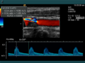
The informative value of sonography can be increased considerably by using the Doppler effect . A distinction is made between one-dimensional methods ( pulsed wave Doppler , continuous wave Doppler , also referred to as D-mode ) and two-dimensional, color-coded applications ( color Doppler - F-mode ). The combination of B-image with pulsed wave Doppler (PW Doppler) is also called duplex .
Doppler methods are used to determine blood flow velocities, to detect and assess heart (valve) defects, constrictions ( stenoses ), occlusions or short-circuit connections ( shunts ), see color-coded Doppler sonography .
principle


The Doppler effect always occurs when the transmitter and receiver of a wave move relative to each other. To determine the speed of blood flow in the blood vessels or in the heart, the echo reflected by the blood cells ( erythrocytes ) is detected . The reflected signal is shifted by a certain frequency compared to the frequency emitted by the transducer: the Doppler frequency . A wave of the frequency emanates from the "resting" transmitter, the transducer ; a moving particle with the flow velocity reflects the sound with the frequency shift . The total frequency shift (with angle between particle trajectory and sound beam,: speed of sound) is


- .

The direction of flow can be reconstructed from its sign . At a given speed, the frequency shift is greater the greater the transmission frequency . In the range from 2 to 8 MHz and flow velocities from a few mm / s up to 2 m / s is about 50 Hz to 15 kHz. To measure the speed exactly, it is necessary to determine the angle (Doppler angle) between the direction of sound propagation and the direction of movement of the erythrocytes (direction of the blood vessel). Since the Doppler principle is angle-dependent and the cosine function is included in the speed calculation, the influence of the same angle measurement errors on the calculated speed, as the increase in the cosine function changes with increasing angle, varies. Since movements of the transducer can hardly be avoided in reality, the errors that arise from this variation of the angle increase disproportionately if the angle between the propagation of the sound and the direction of the vessel varies as a result of the examination. It is therefore generally recommended not to make statements about speeds in examinations with a Doppler angle> 60 °. However, the dependency on the angle can be eliminated, for example by using stereo measuring heads .

The procedures in detail
With the Continuous Wave Doppler (CW-Doppler) method, a transmitter and a receiver in the transducer work simultaneously and continuously. By mixing with suitable high-frequency signals and with electronic filters, the spectrum of the Doppler frequencies or speeds and also the direction can be determined from the returning wave in the evaluation electronics . The disadvantage of this method is that the tissue depth from which the Doppler echo originates cannot be determined. On the other hand, relatively high speeds can also be registered.
On the other hand, with the Pulsed Wave Doppler (PW Doppler), the so-called gate can be set for a location-selective speed measurement in the conventional B-mode . Only the speed of blood particles flowing through this gate is then measured . Ultrasonic signals of short duration are sent from a transducer that functions as both a transmitter and a receiver. The axial spatial resolution is a measure of the device's ability to distinguish objects that are close together in the direction of propagation of a pulse. The better the axial spatial resolution should be, the greater the bandwidth of the transmission signal must be. Therefore, very short pulses of around 2-3 wave trains are usually used. The shorter the pulse duration, the more indeterminate its frequency and the greater the bandwidth. Since small Doppler shifts are no longer visible on a single wave packet due to the signal noise present in the signal , the Doppler frequency is determined with a method using several different successive transmission pulses. Ultimately, one always measures the change in the distance of the scattering particles present in the measurement volume per unit of time. It is an indirect measurement of the Doppler frequency in the time domain. If a limit speed dependent on the pulse repetition rate is exceeded , the speed can no longer be clearly assigned. This effect is called the alias effect .
In color-coded Doppler sonography , the local Doppler frequency (= mean flow velocity) and its fluctuation range are determined for a large area of a conventional ultrasound image (color window) . With this one would like to estimate the turbulence of the flow. Due to the statistical movements of the scattered particles, the fluctuation range of the flow velocity is always greater than the turbulence. The result is superimposed in false colors on the B-image, i.e. in shades of red and blue for different blood speeds and green for turbulence. Here, the color red usually stands for movement towards the transducer, while flows away from the probe are coded with blue colors. Areas of speed 0 are suppressed by the electronics.

Use of the Doppler method in a cardiac examination: mitral valve regurgitation
Color Doppler and PW Doppler. Within the stenosis, the speed is coded in blue because of the high flow velocity and the resulting aliasing effect.

Tissue Doppler in the myocardium


A special application is the tissue Doppler (also tissue Doppler ), in which it is not the blood flow velocities but the velocity of the tissue, in particular the myocardium, that is measured and displayed. Compared to the conventional Doppler method, the frequency shifts are significantly lower, and this examination method therefore requires special device modifications. An application of the tissue Doppler are strain ( elasticity ) and strain rate (elasticity rate) imaging: here the contractility of individual tissue sections of the heart muscle is measured, which one hopes to be able to make better statements about regional wall movement.
More techniques
Advances in digital signal processing with increased computing power opened up new applications for ultrasound devices. By means of digital sound wave coding , it is possible to clearly differentiate ambient noise from the sound wave used to generate images and thus to improve the resolution. Processes based on effects similar to those of 3D sonography allow the generation of panoramic images .
Further Doppler methods were developed. The amplitude-coded Doppler (Powerd-Doppler) does not measure the flow velocity, but the amount of moving particles and thus allows the detection of much slower flows than is possible with the classic Doppler method.
The use of sonographic contrast media ( contrast-enhanced ultrasound ) or the display of blood flows in B-mode refine the possibilities of vascular diagnostics. The importance of contrast media in particular is increasing, since with their help statements about the dignity (benign or malignant) of new tissue formations can be made.
At the end of the 1990s, the B-image display could be improved again in contrast and spatial resolution with Tissue Harmonic Imaging (THI). This method is standard in today's commercial ultrasound systems.
Image errors


When generating images by means of ultrasound, artifacts (image errors) can occur which are not always considered to be disruptive, but can also provide additional tissue or material information.
A very characteristic artifact is the speckle noise, which is caused by the interference of sound waves. It is the cause of the distinctive light and dark spots alternating over a short distance in ultrasound images.
A common artifact is the shadowing ( distal sound extinction ) behind highly reflective objects with an impedance that differs greatly from the rest of the tissue, such as bones, air or concretions (deposits). There is a strong echo when the sound is incident almost vertically, but not when the incident is at an angle.
A distal sound gain is excessively bright shown behind tissue (distal) a structure which absorbs little. In general, in order to compensate for the attenuation of the tissue and, for example, to display liver tissue homogeneously over the entire depth , deeper signals are increasingly amplified with the aid of time gain compensation or also depth gain compensation . For example, if there is a gallbladder in the liver, the liver tissue is significantly lighter than the rest of the liver tissue because bile is less attenuating than liver tissue, but the tissue behind the gallbladder is lightened with the same amplification factor as the surrounding tissue.
In the case of circularly cut objects, the marginal rays can be reflected away; the image then lacks the edge structures and there is shadowing ( lateral shadowing ).
In the case of highly reflective interfaces, multiple reflections ( comet tail artifact , also ring-down phenomenon ) or mirror artifacts in the form of virtual images of objects located in front of the interface can occur.
Objects can appear shifted behind areas with different sound speeds.
At the edge of fluid-filled organs, a less focused impulse when hitting an inclined boundary surface generates echoes with low strength and fuzzy contours. Especially in fluid-filled hollow organs such as the urinary and gall bladder, this layer thickness artifact can simulate non-existent structures.
Inadequate coupling of the transducer to the skin surface causes multiple echoes to appear at the same distance without creating an evaluable image ( reverberations ).
Security aspects
Using ultrasound is a safe method for imaging. Possible sources of harm to humans and animals that come heat generation and cavitation into consideration.
Cavitation
Cavitation (Latin: cavis, -is = the cave) is the effect that cavities or gas bubbles are created in the tissue in the negative pressure phase of a sound wave, which can collapse in the pressure phase and cause tissue damage. This is the same effect that is used in an ultrasonic cleaner. The higher the ultrasound frequency, the higher the peak pressures the tissue (or fluids) can tolerate. If the diagnostically interesting frequencies between 2 and 20 MHz are used, the negative sound pressure may not exceed 15 MPa in order to avoid cavitation in pure degassed water . However, the tissue itself contains so-called "cavitation germs", which promote the formation of cavitation bubbles, so that cavitation in the tissue can occur even at significantly lower negative sound pressures. Cavitation occurs particularly frequently at transitions between media (materials) with a large difference in acoustic impedance. Such transitions are found in the body primarily between soft tissue and bones or between soft tissue and air-filled areas (lungs, intestines). It is currently assumed that cavitation in the human body does not occur below 4 MPa negative peak pressure. Cavitation can also be promoted by ultrasound contrast media, which is why cavitation can occur below 4 MPa when such contrast media are used.
warmth
The amount of heat generated depends on the absorbed sound intensity; Heat is dissipated through blood flow and heat conduction. For healthy tissue, even a long-term temperature increase of 1.5 ° C is harmless. Nevertheless, the exposure time should be limited. The individual procedures in detail:
In B-mode , the power applied per sound pulse is 1 to 10 mW and is distributed over a large volume within a sonication time (for the single pulse) of less than 1 µs and a pulse repetition frequency well below 5 kHz.
In (T) M mode , instead of a volume, a line of tissue is transmitted through with a pulse repetition rate of about 1 kHz.
The pulse Doppler method is also carried out statically, but the pulse repetition frequency is much higher at up to 30 kHz and overheating cannot be ruled out. Therefore, the pulse sequence and transmission sound pressure must be chosen in an appropriate ratio and the examination time must be as short as possible.
With the continuous wave Doppler method , a power of around 10 to 100 mW is constantly applied in a small volume. As with the pulse Doppler, the examination time should be as short as possible.
General
Due to the intensities used in the clinic and careful adjustment and optimization of the parameters (transmission power, pulse sequence, duration of application), a health hazard is unlikely. A study by the Food and Drug Administration ( FDA ) of the USA showed the following safety range: Damage does not occur as long as the applied intensity times exposure time remains below 50 W · s / cm² , although this should not be viewed as a sharp limit.


Internationally there is a safety standard for ultrasonic devices (IEC 60601-2-37), which does not specify any limit values and only requires the disclosure of certain acoustic parameters of a device, provided one of the following criteria is met: negative sound pressure above 1 MPa, maximum spatial, temporal Average intensity over 100 mW / cm², intensity based on the area of the sound transducer of over 20 mW / cm². The manufacturer must create a risk management system. The manufacturer must specify a limit for the safety-relevant parameters (mechanical index MI and thermal index TI) for his device and justify it with regard to the application.
In addition, the FDA warns against unnecessary prenatal examinations for creating pictures or videos as "keepsakes" without any medical indication (justification), as offered by some dubious traders and doctors. Although there are no reliable indications of biological effects caused by exposure to currently used diagnostic instruments, it is possible that such effects will be recognized in the future.
Physical basics
Sonography as an imaging method in medical diagnostics is based on the fact that sound waves propagate at different speeds in different media . They are partially reflected at interfaces of different wave impedance , another part spreads further - often with a changed direction. To simplify matters, the examination of a human can be described with that of a liquid, in which important material-dependent parameters in human tissues and water change abruptly (see Table 1). As the difference in wave impedance increases, the reflected portion also increases. In soft materials, due to the low shear viscosity, only non-polarizable longitudinal waves can propagate.
| medium |
Speed of sound in m / s
|
Wave impedance in kg / (m²s)
|
Density in kg / m³
|
|---|---|---|---|
| air | 340 | 410 | 1.2 |
| Fat / water / brain / muscles | 1500 | 1.5 · 10 6 | 1000 |
| Bone (compact) | 3600 | 6 · 10 6 | 1700 |


The following values for sound parameters are usual for a diagnostic sonographic examination:
- Ultrasonic frequency :
- average sound intensity :
- medium pressure change (relative to atmospheric pressure) .


Sound phenomena
As in wave optics, the sound propagation is accompanied by the phenomena reflection , refraction , diffraction , scattering and absorption . Reflected and scattered sound waves are registered as echoes by the ultrasound probe, and by evaluating their strengths and transit times, it is possible to map the irradiated object.
reflection
For the reflection with perpendicular incidence of the sound at smooth interfaces between areas with different impedance , the reflection factor (i.e. the ratio of the reflected to the incident sound amplitude) is calculated according to:


The following applies to the ratio of the sound intensities:

The greater the impedance difference, the stronger the reflection. In comparison to optics , the impedance behaves analogously to the refractive index . In order to lose as little intensity as possible due to reflection during the transition from the sound-generating probe to the examination object, the impedances of the probe and the body should be small. Air leads to poor coupling of sound into the body (cf. Table 1: the values result ), so a water-based gel is used as the transition medium. For the same reason, air-filled organs such as the lungs and gastrointestinal tract or areas enclosed by bones are difficult or impossible to access for ultrasound examinations: sound waves brought into the body from outside are reflected at the interfaces of these organs.

scattering
In the case of rough interfaces that are not arranged perpendicular to the ultrasound beam, an echo can still be registered because a diffuse radiation cone is scattered back. The scattering of inhomogeneities generates signals characteristic of a tissue structure from areas between interfaces, whereby tissue types can be differentiated. The strength of the scattering changes depending on the diameter of the scattering center. In the “geometric” area (for , with : sound wavelength) the scattering is strong, e.g. B. in vessels. They are brighter in B-mode images. In the “stochastic” area ( ) as in the liver, the scatter is medium and makes up about 20% of the total absorption. In the “Rayleigh range” ( ) the scatter is weak, for example in the blood.


absorption
Sound fields are absorbed due to scattering, internal friction , non-isentropic compression and the stimulation of internal degrees of freedom (molecular rotation, oscillation) of the sound-bearing medium. The energy is converted into heat. The weakening occurs exponentially with increasing distance from the transducer: . The absorption coefficient is tissue and strongly frequency dependent. Since it is approximately proportional to the frequency, a specific attenuation can be specified in dB / (cm · MHz) . For soft tissue it is 1 dB / (cm · MHz). As the sound frequency increases, the range decreases. Therefore, a frequency that is adapted to the required penetration depth (see Table 2) must be selected in order to just be able to examine a certain object with the technically possible amplification. Since the resolution is better at higher frequencies, the highest possible frequency is always chosen. Signals from greater depths have to be amplified more in the evaluation electronics, but this comes up against technical limits. The following table is therefore based on these technical detection limits, which are above 100 dB up to around 10 MHz and drop to around 50 dB up to 40 MHz.


| Frequency in MHz | maximum examination depth in cm
|
Study area |
|---|---|---|
| 1 | 50 | |
| 2-3.5 | 25-15 | Fetus, liver, heart, veterinary medicine (large animals) |
| 3.5 | 15th | Kidney, veterinary medicine (large dogs) |
| 5 | 10 | Brain, veterinary medicine (medium-sized dogs) |
| 7.5 | 7th | Thyroid, mammary gland, superficial vessels, veterinary medicine (small dogs, cats) |
| 8-9 | 6th | Prostate ( endoscopic ) |
| 10 | 5 | |
| 11-12 | 4-3 | Pancreas (intraoperative) |
| 7.5-15 | 7-2 | Breast diagnostics |
| 20th | 1.2 | |
| 21-24 | 1.1-0.9 | Eye, skin |
| 40 | 0.6 | Skin, vessels |
Generation and detection of ultrasound
The generation of ultrasound and the detection of returning echoes mostly take place electromechanically in a transducer that is part of the probe and is based on the piezoelectric effect : In a piezoelectric material, mechanical deformation creates an electrical polarization, a charge on the surface and thus a electrical voltage generated. When the material vibrates, alternating voltage is generated (proof of sound vibrations). Conversely, these crystals vibrate mechanically when an electrical alternating voltage is applied (generation of sound vibrations). Above all, ceramics such as barium titanate, lead titanate, lead zirconate and lead metaniobate are used. These are polarized by strong heating and subsequent cooling with the application of an electrical voltage.
The sound field of a circular ultrasonic transducer
The propagation and intensity distribution of the emitted sound waves, which are limited by diffraction, can be derived to a good approximation from the assumption of Huygens' principle that every point on the transducer surface emits a spherical wave. The result can be divided into areas depending on the distance to the converter:

The close range is characterized by strong interference, which results in a very inhomogeneous distribution of intensity. In the far range a continuously widening beam is formed. In the focal range (between near and far range) the intensity is bundled and decreases perpendicular to the beam axis. With : transducer diameter,: sound wavelength, it lies between


the expression or its approximation is also referred to as the near-field length.


The example shows the sound field of an unfocused ultrasonic transducer with a frequency f = 4 MHz, a diameter of the transducer of 10 mm for water with a speed of sound of c = 1500 m / s, determined by simulation calculations . The amplitudes of the sound pressures are displayed. The near field length is N = 67 mm. One recognizes the strong fissures of the sound field in the close range and the gradual decay of the sound pressure in the far range.
The sound field of a focused ultrasonic transducer
The ultrasound can be focused by the curvature of the transducer surface, by using an acoustic lens or - with appropriately designed multi-channel transducers - by a suitable time-delayed control of the individual elements. Basically, the focusing takes place on a point within the near field length, which is typically aimed for in the area . In principle, it is not possible to focus on locations further away than the near field length.

The example shows the sound field of the same ultrasonic transducer determined by simulation calculations as in the previous section. The focus is achieved by the curvature of the transducer surface (radius of curvature R = 30 mm). The amplitudes of the sound pressures are displayed.
Resolving power
The spatial resolution is a measure of the ability of a measuring device to separately perceive objects that are close together. A distinction is made between the resolution in the direction of the beam axis (axial) and perpendicular to the axis (lateral).
Lateral
The lateral resolution is determined by measurement by pushing a point-shaped object within the focal area in front of the transducer perpendicular to the direction of sound propagation and plotting the amplitude of the echo signal as a function of the location (i.e. the distance from the beam axis). The width at which the amplitude of the received signal has decreased by 6 dB compared to the maximum, on both sides of the maximum, is taken as a measure of the lateral spatial resolution. The following applies approximately ( : diameter of a circular transducer) in the focal area. Outside the focal range, the lateral resolution decreases with increasing distance from the transducer.


Mathematically, the lateral resolution results from the 6 dB limit of the so-called transmit-receive field, that is, the squares of the sound pressures calculated for the respective measurement arrangement. The squaring of the sound pressures takes into account that the directional effect of the ultrasonic transducer is effective both during transmission and reception.
The example shows an x / y section of the ultrasonic transducer described above (4 MHz, transducer diameter 10 mm, near field length N = 67 mm) in the focus at z = 67 mm. The 6 dB limit is colored yellow and has a width of approximately 2.8 mm.
Axially
Two layers of tissue lying one behind the other in the direction of sound can just be perceived separately if two distinguishable echoes emanate from the boundary surfaces. The main factors that determine the axial resolution are:
- the sound frequency and
- the duration and form of the excitation signal
When using the simple echo method, the resolving power improves with increasing frequency, and it deteriorates with the length of the excitation signal. Typically, broadband ultrasonic transducers are used and stimulated with a short rectangular pulse. The length and shape of the excitation signal are usually not variable and the resulting echo signals from a tissue layer have about 2 or 3 oscillations with a gradually rising and falling envelope . The received signals can only be distinguished if they do not overlap in time. Due to the double sound path in the pulse-echo method (there and back), a transmission signal with a length of 3 oscillations requires a minimum distance between the layers of 1.5 ultrasound wavelengths. In the case of a signal with a frequency of 5 MHz, for example, a wavelength of and thus an axial resolution of approximately 0.45 mm results .

When using specially coded broadband excitation signals, the duration of the excitation signal is not the only decisive factor, since the echo signals can be greatly shortened and thus separated using suitable mathematical methods. By the pulse compression with eg chirp that is signals correlation function of transmitter and receiver signal evaluated. In this way, despite the longer signal duration, significantly better signal resolution and freedom from noise are achieved than with the simple echo method. It is currently mainly used in research.
Usual values
Typical spatial resolutions that can be achieved depending on the transmission frequency are:
| Frequency: | 2-15 MHz |
| Wavelength (in muscles): | 0.78-0.1 mm |
| Penetration depth (simple): | 12-1.6 cm |
| Local resolution lateral: | 3.0-0.4 mm |
| Axial spatial resolution: | 0.8-0.15 mm |
The ultrasound market
The price of ultrasound devices varies greatly depending on the equipment (e.g. number of probes and additional software) and quality. The size varies from smartphone size to laptop format and size to systems weighing 200 kg that resemble a narrow desk with a PC on castors. Simple Doppler devices for listening to the heartbeat of fetuses are also on the market.
The total volume of sales “in ultrasound” in 2004 was around four billion dollars worldwide and is growing annually by around three to four percent. The most important suppliers are GE, Philips, Siemens and Toshiba with market shares of 20 percent each. The segments with 3D and 4D display are growing the most. In addition, the market for handheld devices is growing rapidly; here Sonosite is the market leader. About as many systems are placed in the cardiology and radiology segments as in obstetrics.
education
The training in the specialist field of sonography takes place in the German-speaking area partly already during the medical studies. However, the majority of the training takes place during the respective specialist training. There are various sub-specializations in sonography: B. Echocardiography, which is learned during the corresponding specialist training to become a cardiologist.
In contrast to this, there are special training programs or courses of study in other health systems that aim to become a sonographer. The USA is an example here.
Ultrasonic simulation
During medical studies, but also during the respective specialist training, it can be difficult to have both patients and experienced ultrasounders available to practice at the same time. The ultrasonic simulation market has established itself accordingly. There are different systems with different functions.
Phantoms
For phantoms, models are used as well as an ultrasound device. These phantoms should now show realistic recordings when sonicating with the real device.
Simulators
Ultrasonic simulators are offered in different designs. So there are whole devices that simulate the ultrasound examination by means of structures that are supposed to represent a transducer. The images generated are usually generated artificially, similar to a computer game. These simulator devices can range in price from a few thousand to 100,000 € when fully equipped.
Ultrasonic simulator apps
Ultrasound simulator apps have also recently become available. These offer the advantage that many patient cases can be practiced completely portable. With some manufacturers, the images generated are sometimes even real, so that a higher degree of realism is possible. The control takes place directly on the tablet or smartphone or using an optional additional app that transforms the smartphone into a virtual transducer to control the tablet.
The first realistic ultrasound simulator app was developed in 2018 by the company Scanbooster.
See also
- Special Techniques: Intravascular Ultrasound · Endobronchial Ultrasound
- Areas of application: prenatal diagnosis · echocardiography · fine ultrasound · endosonography · breast ultrasound
- Similar procedures: elastography · optical coherence tomography · neutron tomography · laser scanning
literature
- Cornelius Borck: Ultrasound Diagnostics. In: Werner E. Gerabek , Bernhard D. Haage, Gundolf Keil , Wolfgang Wegner (eds.): Enzyklopädie Medizingeschichte. De Gruyter, Berlin / New York 2005, ISBN 3-11-015714-4 , p. 1428 f.
- Christoph F. Dietrich (Ed.): Ultrasound course. Organ-related presentation of basic, advanced and final courses. According to the guidelines of KBV, DEGUM, ÖGUM and SGUM. 6th, completely revised and expanded edition. Deutscher Ärzteverlag, Cologne 2012, ISBN 978-3-7691-0615-2 .
- Olaf Dössel : Imaging procedures in medicine. From technology to medical application . 1st edition. Springer, Berlin a. a. 2000, ISBN 3-540-66014-3 .
- H. Fendel (Ed.): Praenatale Dopplerdiagnostik. Doppler sonography and morphology of the uterofetoplacental vascular supply in high-risk pregnancies . Steinkopff, Darmstadt 1992, ISBN 3-7985-0919-0 .
- T. Grau (Ed.): Ultrasound in anesthesia and intensive care medicine. Ultrasound Diagnostic Textbook . Deutscher Ärzte-Verlag, Cologne 2007, ISBN 978-3-7691-1200-9 .
- Heinz Morneburg (Hrsg.): Imaging systems for medical diagnostics. X-ray diagnostics and angiography, computed tomography, nuclear medicine, magnetic resonance tomography, sonography, integrated information systems . 3rd substantially revised and expanded edition. Publicis MCD Verlag, Erlangen 1995, ISBN 3-89578-002-2 .
- Carl-Detlev Reimers, Hartmut Gaulrapp, Henrich Kele (eds.): Sonography of the muscles, tendons and nerves. Examination technique and interpretation of findings . 2nd revised and expanded edition. Deutscher Ärzte-Verlag, Cologne 2004, ISBN 3-7691-1188-5 .
- Günter Schmidt (Hrsg.): Ultrasound course book. According to the guidelines of DEGUM and KBV . 4th completely revised and expanded edition. Thieme Verlag, Stuttgart u. a. 2004, ISBN 3-13-119104-X .
- Günter Schmidt (Ed.): Sonographic differential diagnosis. Teaching atlas for systematic image analysis with over 2500 examples of findings . Thieme Verlag, Stuttgart u. a. 2002, ISBN 3-13-126141-2 .
- Bernhard Widder, Michael Görtler: Doppler and duplex sonography of the vessels supplying the brain . 6th expanded and fully revised edition. Springer, Berlin a. a. 2004, ISBN 3-540-02236-8 .
- Klaus Vetter : Doppler sonography in pregnancy. Weinheim u. a., Basel u. a. 1991, ISBN 3-527-15472-8 .
Web links
- Internal sonography atlas of the Albertinen Hospital Hamburg
- Mannheim-Ludwigshafen Ultrasound Colloquium: Links to ultrasound websites and case collections, extensive case collection
- German Society for Ultrasound in Medicine (DEGUM)
- Overview and modern developments (in English)
Individual evidence
- ↑ Steiner / Schneider, Doppler sonography in obstetrics and gynecology, 3rd edition, ISBN 3-642-20938-6 , p. 72 f.
- ↑ Kubale R et al. (2002) Color-Coded Duplex Sonography: Interdisciplinary Vascular Ultrasound ISBN 3-13-128651-2
- ^ David H. Evans, W. Norman McDicken: Doppler Ultrasound - Physics, Instrumental, and Clinical Applications. 2nd edition, Wiley, 2000, ISBN 978-0-471-97001-9 .
- ↑ George R. Sutherland, Liv Hatle, Piet Claus, Jan D'Hooge, Bart H. Bijnens: Doppler Myocardial Imaging: A Textbook . BSWK bvba, 2006, ISBN 90-810592-1-1 .
- ↑ http://www.uniklinik-duesseldorf.de/fileadmin/Datenpool/einrichtungen/klinik_und_poliklinik_fuer_strahlentherapie_und_radioonkologie_id30/daten/ultraschall_eine_einfuhrung.pdf page 17.
- ↑ http://www.uniklinik-duesseldorf.de/fileadmin/Datenpool/einrichtungen/klinik_und_poliklinik_fuer_strahlentherapie_und_radioonkologie_id30/daten/ultraschall_eine_einfuhrung.pdf page 18.
- ↑ Elfgard Kühnicke: Elastic waves in layered solid-state systems - modeling using integral transformation methods - simulation calculations for ultrasonic applications . TIMUG e. V., ISBN 3-934244-01-7 .
- ↑ J. Krautkrämer, H. Krautkrämer: Materials testing with ultrasound. Springer, Berlin, ISBN 978-3-540-15754-0 .
- ↑ T. Misaridis, JA Jensen: Use of modulated excitation signals in medical ultrasound. (PartI-III), 2005, IEEE Transactions on Ultrasonics, Ferroelectrics and Frequency Control ( PDF ( Memento from July 3, 2010 in the Internet Archive ))
- ↑ PR leap, October 27, 2006, accessed January 28, 2009
- ↑ Frost & Sullivan Research Services, October 26, 2004, accessed January 28, 2009
- ↑ Sonography seminar & internship | Ulm University Hospital. Retrieved November 26, 2019 .
- ↑ German Medical Association: (M uste r) logbook Documentation of further training in accordance with (sample) further training regulations (MWBO) on further training for specialists in internal medicine and cardiology. (PDF) In: German Medical Association. German Medical Association, February 18, 2011, accessed on November 26, 2019 .
- ↑ Student Resources: ARDMS Prerequisites & Application Guides. Retrieved November 26, 2019 .
- ↑ Fetus Ultrasound Examination Phantom "SPACEFAN-ST" | Products: Imaging Phantoms for Ultrasound / Radiology Exam Training | Kyotokagaku Co., Ltd. Retrieved December 7, 2019 .
- ↑ ScanTrainer Transabdominal Ultrasound Simulator | TA skills training. Retrieved December 7, 2019 (American English).
- ↑ ScanTrainer | Curriculum-Based Ultrasound Skills Training Simulator. Retrieved December 7, 2019 (American English).
- ^ Products. Retrieved December 7, 2019 (American English).
- ↑ Welcome to Scanbooster, the world's first realistic Ultrasound Simulator App. Retrieved December 7, 2019 (UK English).
- ↑ Scanbooster PRO Ultrasound Simulator App - Realistic Sonography. Retrieved December 7, 2019 (UK English).
- ↑ Welcome to Scanbooster, the world's first realistic Ultrasound Simulator App. Retrieved December 7, 2019 (UK English).