
Technical drawing
A technical drawing is a predominantly in mechanical engineering used document , which in graphical and partially in writing the for the manufacture of a single part or assembly to a module or the complete machine contains the necessary information and as part of the technical product documentation is used.
DIN 199 defines the following: “A technical drawing is a drawing in the type and completeness required for technical purposes, e.g. B. by adhering to presentation rules and dimension entries. ”This definition takes into account the complex process that is required for the creation of complete, standard-compliant technical drawings and is called technical drawing .
The technical drawings used in construction are called construction drawings . The following elaboration mainly deals with technical drawing in mechanical engineering.
Types of representation

In the earliest drawings, the vivid perspective ( three-dimensional ) representation was used - initially in a primitive manner and from the Renaissance onwards in a correct manner.
Because it makes relatively high demands on the talent of the draftsman, at the beginning of industrialization (18th century), two-dimensional images of the objects in right-angled parallel projection ( orthogonal projection ) were used. The edges and symmetry lines of most technical objects are arranged at right angles to one another. A right-angled coordinate system can be superimposed on them and views (front / rear view, side view from right / left and top / bottom view) can be generated in one direction of the coordinate axes. The areas in the three coordinate planes are mapped without distortion. With the parallel projection used, the image scale is independent of the distance between an object plane and the viewer; all lengths are shown to scale. The disadvantage is that the observer has to imagine the geometry of the body from several views (and possibly sections in the case of bodies with cavities).
So-called axonometric projections have always been used in parallel to orthogonal projection . These are mainly intended for technical laypeople, because they are perspective (three-dimensional) representations. Because of the effort involved in drawing and the use of only one or two image scales, it is not arbitrary, but selected and parallel axonometric projections from selected directions:
- Isometric axonometry - a 1: 1: 1 image scale
- Dimetric axonometry - two image scales 1: 1: 0.5.
In the case of technical drawing with a computer ( CAD ), any desired perspective representation (also in central projection ) can now be generated without any special effort , because the requirement for a special talent for drawing is no longer required.
Types of drawings
In mechanical engineering, a distinction is made between partial drawings and assembly drawings.
Parts drawing

Assembly drawing

Exploded view


Part or part drawings
They contain the dimensioned representation of a component and are used for
- the work planning ,
- for the provision of the material z. B. Separation of a blank from a semi-finished product ,
- for processing ( shaping is the main part of production ),
- for any heat treatment (e.g. hardening ),
- for any surface treatment (e.g. painting ) and
- for final parts inspection .
A part drawing usually contains only one component.
Two part drawings are made for forged , (hot) pressed and cast parts : raw part and finished part drawing .
Assembly drawings
The entire machine, apparatus or device ( overall drawing ) or an assembled component group ( group drawing ) is shown on an assembly drawing .
Assembly drawings can also contain representations that clarify the composition of the individual parts and their common function (so-called exploded views ). This facilitates assembly, repair and, in general, understanding of the product.
Other types of drawings
Separate drawings are often made for repair instructions (including spare parts catalogs and instructions for use ) and publications (including brochures ).
plans
Plans show how several machines or, in particular, the parts of larger technical systems are arranged in relation to one another. Examples are site plans and pipeline plans .
Electrical circuit diagrams are made to illustrate the electrical drive and electrical control of machines.
Rules and standards in drawing
The standardization in the production of technical drawings (in short: in the drawing system ) is on the one hand a parallel to the replacement construction , which it promotes on the other hand. It takes place both by means of national (e.g. DIN ), but in the course of development more and more by means of international standards or industrial norms (especially ISO ).
The departure from the historical, individually designed drawing is comprehensive and goes down to the last detail. The individual technical draftsman can no longer be recognized by a personal touch, but only by how skillfully he applies the rules and standards.
The following is standardized (this list is a short summary, in detail there are many more agreements):
The drawing sheet
- Sheet sizes in A-series paper format
- Drawing scale ; Selection series for reduction or enlargement ratio between object and representation according to ISO 5455
- Natural scale: 1: 1,
- Reduction ratios: 1: 2; 1: 5; 1:10 ... and 10 n multiples thereof,
- Magnification ratios: 2: 1; 5: 1; 10: 1… as well as multiples thereof;

-
Title block in the lower right corner of the drawing sheet
- Entries according to EN ISO 7200 : designation of the product, drawing number , material information , scale, creation / test notes , version history / revision status , etc. a.,
- possible expansion of the title block upwards with a parts list for listing the components (designation and number) in the case of assembly drawings (separate parts list / s, if there is insufficient space for larger assemblies);
-
Lettering using inclined or vertical standard font for technical drawings ( Latin or Greek letters and Arabic numerals )
- Selection series for font size (height) from 2.5 mm to 6 mm.
The representation


Views
- You can choose the main view (front view) (possibly the main view when using the object or the view that best shows its shape, so that some views can be dispensed with; in most cases not all of the 6 views shown in the adjacent picture are required anyway) ,
- Rotation position (vertical or horizontal) of the object as in use (finished product) or in production (component)
Cuts
Sections complement the views from the outside. They are necessary when shapes inside a body are difficult or impossible to recognize from the outside. Part of the body is thought to be cut away and a view of the remaining part of the body is created.
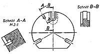
- Hatching: The resulting cut surfaces are indicated by hatching . The cut section through a rib remains unshaded. so that this point does not give the impression of a mass accumulation (see 2nd picture in the picture row below). Imagine the rib so thin that it misses when cutting, the cut is made parallel in front of it.
- Rotation position: It corresponds to the sectional view looking towards the cut surface (see 3rd picture in the picture row below: Section AA).
- Full cuts: The body is cut completely in a straight cut perpendicular to the plane of the paper and mostly in one of its planes of symmetry. Bent cuts are also possible.
- Partial sections: They are created if the supplement to full sections does not contain any further information. If the cut affects only one detail, it is cut away from its surroundings. In the case of kinked and detailed cuts, the cutting line must be shown.

Sectional images of a sleeve

Kinked full section of a flange
Partial sections on details of a pane


Line types and widths
Different line types and widths have different meanings in technical drawing:
- wide solid line in general for visible body edges and outlines,
- narrow solid lines especially for dimension and auxiliary lines, hatching and gear wheel base circles,
- (narrow) dashed lines for invisible, hidden body edges and outlines,
- (narrow) dash-dotted lines for axes of symmetry , axes of rotation , pitch circles , bolt circles , etc. a.,
- (narrow) freehand and zigzag lines for break lines with interrupted display of long components, borders of partial sections, etc. a.

wide solid line

narrow solid line

Dashed line

Dotted line

Freehand line

Zigzag line
The line widths are set relative to each other in selection groups:
| Line group | Preferred for sheet format | Line width in mm | ||
|---|---|---|---|---|
| 0.5 | A2 and smaller | 0.25 | 0.35 | 0.5 |
| 0.7 | A1 and A0 | 0.35 | 0.5 | 0.7 |
Table according to DIN
According to ISO there are also the line groups 0.25; 0.35 and 1. There, however, the middle line widths that are provided in DIN for lettering and hidden edges and outlines are missing.
Dimensioning
The objects are drawn to scale, but their dimensions must always be given numerically. A measurement by measuring in the drawing is possible, but not binding. The dimensioning is i. d. Usually made by the designer and simply entered in the drawing by the draftsman. Since all dimensions can only be achieved within a tolerance range in production , it is also important to which form element each dimension relates. The decision is the construction work involved in the manufacturing process.

The dimensions essentially concern length and angle dimensions with so-called nominal dimensions and permissible tolerance widths. In many cases, the tolerance range does not apply because that which can be achieved with conventional production without any special effort is often sufficient. This is recorded in generally applicable standards and divided into several degrees of accuracy: General tolerances according to ISO .
The figure on the right shows the basic elements of length dimensioning: Basic elements of dimensioning (see illustration on the right) are:
- Dimension arrow on the left
- Dimension line
- Dimension (unit of measurement is millimeter mm , is not entered)
- Witness line
- Dimension arrow on the right
In the case of angular dimensioning, the extension lines form the angle marked with the dimension number (unit of measure o is entered), and the dimension lines are arcs.
The following series of images also includes dimensions of cylindrical contours (here bores , generally also shafts ). The top views (pictures 2 and 4) could be omitted because the prefix ø (for diameter , 1st and 2nd picture) or M (for thread diameter, 3rd and 4th picture) is sufficient to identify the circular shape .
Figures 3 and 4 also show the usual, only symbolic drawing of threads with two lines: a wide solid line for the limitation against air, a narrow solid line for the limitation in the material (deepest extension of the thread).
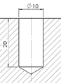
1. Hole, cross-
section
2. Hole or pin,
top view
3. Threaded hole, sectional view
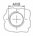
4. Threaded hole, top view

5. Tolerated dimensions on a flange


The two limits of a tolerance field are written after the dimension number (see 5th picture in the above row; the second limit is ± 0 in each case). If a fitting system is used for the combination of components, the dimension number is supplemented with a corresponding code (contains the tolerance field as values relative to the nominal dimension: a) width, b) position).
For the large number of shape and position tolerances, there are special rules for presentation (see the main article). Because of the high effort involved in checking them, they are only used when there are particularly high demands on the quality of the components.
Partial drawings require a large number of dimensions in order to fully describe the components. Assembly drawings contain little or no dimensions. The few concern those dimensions that have to be achieved during assembly by positioning or adjusting .
More labels
The smoothness required during production by machining is noted with triangles as symbols for the permissible roughness depth on the respective surface.
For the surface treatments (e.g. painting ) and heat treatments (e.g. annealing of the material from which the component was made, usually a metal), which are usually carried out at the end, labels pointing to the surface parts or areas concerned are attached .
Saving of drawing work
To save drawing work, there are special rules in special cases:
- Bolt circles in flanges : only partial circle with the holes in the flange instead of a complete top view,
- Details: Enlarged excerpts instead of complete enlarged views / sections (see left in the 3rd row image in the section Sections ),
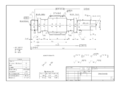
- Long objects: Intermediate pieces cut out without any special additional shape features and end pieces pushed together instead of a complete illustration on a larger drawing sheet (e.g. long waves , bars, etc.),
- Frequently recurring shapes: shape shown only once, number noted and area marked instead of a complete display (e.g. saw teeth, perforated fields )
- Frequently recurring standardized forms: symbolic representation, number noted and area marked (e.g. thread , standard gears, etc.),
- symmetrical objects: representation of only half of mirror-inverted or rotationally symmetrical (e.g. turned parts ) instead of a complete representation,
- u. a.
Overview of standards
A complete presentation of all valid standards for technical drawing is not intended at this point. Rather, the most important standards that are used in technical drawing are to be listed here. For further details, please refer to specific literature on the subject. Specific standards for architectural drawings are listed in the Standards section of the relevant article.
DIN standards
| standard | Area | content | description |
|---|---|---|---|
| DIN 5 | presentation | Isometric and dimetric representation | Use in technical drawing (replaced by ISO 5456-3 ) |
| DIN 6 | presentation | Views and sections | Representation in technical drawing (replaced by ISO 128 ) |
| DIN 15 | presentation | Line styles | Use of solid lines, freehand and zigzag lines, dash-dotted lines (axis), dash-two-dot lines, etc. in technical drawing (replaced by ISO 128-20 or ISO 128-24) |
| DIN 30 | presentation | Simplified representations | Use in technical drawing |
| DIN 199 | Terms | Technical product documentation | Terms and definitions for CAD models, technical drawings and parts lists for technical product documentation in the field of mechanical technology. |
| DIN 201 | presentation | Hatching and colors | Use in technical drawing (replaced by ISO 128-50) |
| DIN 406 | labeling | Dimension entries, tolerance symbols, etc. | Use in technical drawing |
| DIN 919 | Wood processing | Technical drawings, woodworking | Use in technical drawing |
| DIN 1356 | Construction drawing | Representation of lines and hatching in construction drawings | Use in technical drawing |
| DIN 2429 | Pipeline construction | Pipelines icons | To be used for technical drawing of pipelines |
| DIN 2481 | Thermal power plants | Thermal power plant icons | To be used for technical drawing of circuit diagrams |
| DIN 6771 | Paper sizes | Drawing sheet formats | Classification and labeling for technical drawing ((Part 6 corresponds to the previous DIN 823 ), August 1999 replaced by EN ISO 5457 , paper format , Part 1 replaced by EN ISO 7200 ) |
| DIN 6775 | Drawing devices |
|
Test standard for ink pens, drawing and writing templates (replaced by ISO 9175 ) |
| DIN 6776-1 | labeling | ISO standard font | Use in technical drawing (replaced by EN ISO 3098 ) |
| DIN 7154 | Fits | System of fit unit bore | Use in technical drawing |
| DIN 7155 | Fits | Fit system unit shaft | Use in technical drawing |
| DIN 7157 | Fits | Selection of fits in the unit bore system | Use in technical drawing |
| DIN 7182 | Terms | Basic concepts of tolerances and fits | Use in technical drawing (replaced by ISO 286 –1) |
| DIN 24300 | Fluid technology | Circuit symbols for oil hydraulics and pneumatics | Technical drawing of hydraulic and pneumatic circuit diagrams |
| DIN 40900 | Electrical engineering | Electrical symbols | Technical drawing of electrical circuit diagrams (replaced by DIN EN 60617 ) |
ISO standards
| standard | Area | content | description |
|---|---|---|---|
| ISO 128 | presentation | Technical drawings | General principles of presentation |
| ISO 286 | Fits | Fits | ISO tolerance system for fits |
| ISO 1219 | Fluid technology | Fluid power circuit diagrams | Requirements for creation |
| ISO 2162 | presentation | feathers | Representation in technical drawing |
| ISO 2768-1 | presentation | General tolerances for lengths and angles | Use in technical drawing |
| ISO 2768-2 | labeling | General tolerances for shape and position | Use in technical drawing |
| ISO 5455 | labeling | Standards | Use in technical drawing |
| ISO 6410 | presentation | thread | Representation in technical drawing |
| ISO 9175 -1 | Drawing devices |
|
Test standard for ink pens, drawing and writing templates |
EN ISO standards
| standard | Area | content | description |
|---|---|---|---|
| EN ISO 1302 | labeling | Surface textures | Information in technical drawing |
| EN ISO 3098 | labeling | Technical product documentation, fonts | Use in technical drawing (replaces DIN 6776-1) |
| EN ISO 5457 | Paper sizes | Sheet sizes | Use in technical drawing (replaces DIN 6771 -6) |
| EN ISO 7200 | Title block | Data fields in title blocks and document master data | Use in technical drawing (replaces DIN 6771-1) |
Creation, duplication, archiving and distribution
In the past, technical drawings were created directly on paper, duplicated through breaks and the originals carefully kept. In the course of time, various duplication processes for technical drawings have developed, some of which are still used today.
The use of CAD software and the copies of the CAD data that this makes it possible to partially displace the paper form of the technical drawing, but mostly the drawings created with CAD are also printed out , plotted or the necessary number of copies simply reproduced with a copier .
Document management and electronic archive systems are increasingly being used for version management and the provision of technical drawings in digital form. The necessary data is stored in these as DWG, DXF, IFC, among other things.
Paper drawings and microfilms are often used for archiving , since digital archiving required (e.g. in mining) cannot be guaranteed unchanged over several centuries. The PDF / A1 format is recommended for short-term archiving . Other formats such as pixel-based data formats are common.
See also
literature
- Willy Groh: The technical drawing. Verlag Technik, 1968
- Hans Hoischen, Wilfried Hesser: Technical drawing . 32nd edition. Cornelsen 2009, ISBN 978-3-589-24132-3 .
Web links
- Tips on how to make an engineering drawing , accessed November 6, 2011
- Tables and notes on technical drawings , accessed on November 6, 2011
Individual evidence
- ↑ Willy Groh: The technical drawing . 8th edition. Verlag Technik, 1968, p. 11
- ↑ Willy Groh: The technical drawing . 8th edition. Verlag Technik, 1968, p. 14
- ↑ p. 77 ff. (PDF; 3.6 MB)
- ↑ SOURCE: DIN 21902-2: 2008-08
- ↑ ( page no longer available , search in web archives: source )
- ↑ TIFF G4 as the predecessor format to PDF / A1 ( Memento from September 17, 2012 in the Internet Archive ; PDF) & Google Books