
Fluorescent lamp

The fluorescent lamp is a low-pressure gas discharge tube , a special metal halide lamp that is coated on the inside with a fluorescent phosphor. In contrast to the fluorescent tube or the cold cathode fluorescent tube, it has hot cathodes that emit electrons through the Edison-Richardson effect (glow emission).
Mercury vapor is used as the gas filling to emit ultraviolet radiation and, in addition, usually argon . The ultraviolet radiation is converted into visible light by the phosphor coating .
history

The first forerunner of the modern fluorescent lamp is the Geissler tube (named after Heinrich Geissler , who invented it in 1857). It consists of an evacuated glass tube with an electrode at each end. The tube is filled with a gas (e.g. neon , argon or simply air ) under low pressure. If you apply a high voltage to the two electrodes, the gas inside begins to glow. In the 1880s this tube was produced in large numbers. It was mainly used for entertainment as it was not bright enough for lighting purposes. Nikola Tesla used fluorescent tubes in his laboratory and planned to equip all households with fluorescent lamps that glow wirelessly in the presence of the electromagnetic alternating field of a Tesla transformer .
In 1901 Peter Cooper-Hewitt invented the mercury vapor lamp , which emits blue-green light. Because of its high efficiency, it was used in photography . The light color was still of little importance in black and white photography at that time . In 1913, Philipp Siedler developed fluorescent tubes filled with inert gas. In 1926, Edmund Germer suggested increasing the pressure inside the tube and coating the tube with a fluorescent substance that converts ultraviolet radiation into visible light. The company General Electric later bought Germer's patent and produced from 1938 lamps with commercial success.
Since then, fluorescent lamps have become widespread, particularly in workplace lighting. Since around 1980 they have also been available as compact fluorescent lamps , which - in the version with integrated ballast and E14 or E27 lamp base - are increasingly replacing incandescent lamps in the household sector . Recently, LED light sources have increasingly taken on this function.
function
- Gas discharge
A high ignition voltage is required to ignite the lamp , because the current can only flow after the gas filling of the fluorescent lamps has been ionized . The value of the required ignition voltage can be reduced by preheating the electrodes. After ignition, the gas becomes electrically conductive and a low-pressure plasma is formed , which is maintained as long as the u. a. gas pressure dependent minimum current is exceeded. Even if the value falls below this level, the plasma needs a short time to recombine , so that when the lamp is operated with alternating current, it is retained even when the current direction is reversed. This applies to all gas discharge tubes .
The plasma has a negative differential resistance due to the impact ionization . If a larger current is impressed on the lamp, the voltage drop between the electrodes decreases . The operating point is therefore not stable and if the series resistor for current limitation is too low, the lamp will be destroyed. This is why fluorescent lamps, like all other gas discharge lamps, must be operated with a ballast . When operating with alternating current, an inductance is used in series with the lamp. Direct operation with direct current , which in principle would be conceivable with a series resistor as a current limiter or a constant current source, is problematic due to the segregation processes of the ion types in the lamp; an inverter that converts the direct current into alternating current is considerably cheaper . Since the 1990s, fluorescent lamps have often been operated with electronic ballasts (EVG) that generate alternating voltage from 32 kHz to over 40 kHz. This usually eliminates the 100 Hz flicker, which some people find annoying.
The plasma emits light when the mercury atoms are excited by the accelerated free electrons and then fall back to a lower energy level . In the case of mercury gas, predominantly ultraviolet radiation with only a small proportion of visible light is emitted. This becomes visible when the fluorescent coating of a lamp does not reach all the way to the end cap or has fallen off due to vibrations.
Fluorescent
In order to increase the yield of visible light, the inside of the discharge vessel is coated with a fluorescent material (hence the name fluorescent lamp) which begins to fluoresce in the visible spectrum as soon as it is exposed to UV radiation. The phosphor converts a large part of the UV radiation into visible fluorescent light . The rest of the ultraviolet radiation is largely absorbed by the glass of the lamp, so that only harmlessly little harmful UV radiation penetrates the lamp.
The phosphor used is a mixture of different phosphors, depending on the lamp color. The light color can be adjusted through the mixing ratio. Halophosphate used to be common, the current technology is triphosphorus. A particularly good color rendering is achieved with the so-called five-band phosphors. Not only do individual light wavelengths occur, which mix to form “white” light, but also wider, adjacent areas, so that an almost continuous spectrum is created, which leads to better color rendering. Phosphors with a fluorescence decay time of at least 1/100 of a second reduce the 100 Hertz flicker (twice the mains frequency ), but much longer afterglow (> 1 s) is undesirable. But there are also versions with an afterglow time of a few minutes, for example to bridge the time until the emergency lighting is activated in the event of a power failure.
Single-color fluorescent lamps are also offered for decorative and advertising purposes. Black light lamps, which almost only shine in the UV range, are also coated with a fluorescent substance that converts dangerous UV-B rays into the UV-A range. In addition, the glass bulb is made in such a way that it absorbs most of the visible light, with the exception of the slight violet shimmer, which is caused by the weak perception of long-wave UV light.
Standardized sizes
The tube diameter of fluorescent lamps is standardized. After the letter "T" (for "tube") the diameter is in eighths of an inch (25.4 mm / 8 = 3.175 mm). A T5 tube has e.g. B. a diameter of about 5 ⁄ 8 inches or 16 mm. In addition to the inches, there are also millimeters: T5 and T8 become T16 and T26 (see table).
Development began with T12 tubes and is moving towards slimmer tubes that require less material and volume for transport, storage and installation and are more efficient. The most common today are T8 and T5 as well as T4 in space-saving light strips (e.g. for shelves). T5 lamps are available in two versions: high light output (abbreviation HO, " High Output ", or FQ, " Fluorescent Quintron ") or high efficiency (HE, " High Efficiency ", or FH, " Fluorescent High Efficiency "). The HO lamps are shorter than HE lamps with a comparable output. In addition, there are individual types of HO and HE lamps with a further eight to ten percent lower electrical output with the same luminous intensity.
The lamp bases for tubes are standardized, as is the pin spacing of the lamp bases at both ends of the straight designs. In some cases, identical sockets (same pin spacing) are used for different tube diameters. This means that T8 lamps fit into the sockets of the older T12 lamps and can replace them. In addition to the straight fluorescent lamps, there are also ring-shaped and U-shaped versions, the latter mostly with a G13 base.
| Type | T2 (rod shape) |
T4 | T5 | T8 | T9 | T10 | T12 | T5 (with a base on one side; rod or U-shape) |
T8 (U-shape) |
T5 (ring shape) |
T4 (ring shape) |
T9 (ring shape) |
T6 (double ring shape) |
|
|---|---|---|---|---|---|---|---|---|---|---|---|---|---|---|
| Diameter in mm | 7th | 13 | 16 | 26th | 29 | 32 | 38 | approx. 22 | 26th | 16 | 13 | 28 or 30 | 20th | |
| Length or diameter in cm | 21.8 32.0 42.2 52.3 |
20.6 30.8 40.8 50.9 91.3 |
s. u. | s. u. | s. u. | see tube socket | 12 to 85 | 22.8 30 |
12.2 | 20.3 22.8 27.9 30.5 40.6 |
19 22.8 |
|||
| base | W4.3 W4.3x8.5d |
WP4.5x8.5d | G5 | G13 | G10q |
2G13-41 2G13-56 2G13-92 2G13-152 |
2GX13 | G10q | ||||||
The lengths are also standardized for the straight design of fluorescent lamps (length without contact pins):
| Type | T4 | ||||||
|---|---|---|---|---|---|---|---|
| Power in W | 6th | 8th | 12 | 16 | 20th | 24 | 30th |
| length in mm | 205 | 325 | 355 | 454 | 552 | 641 | 751 |
| Type | T5 | ||||||||||||||||
|---|---|---|---|---|---|---|---|---|---|---|---|---|---|---|---|---|---|
| Power in W | 4th | 6th | 8th | 13 | 14 U | 24 HO | 21 U | 39 HO | 25 U | 28 U | 50 HO | 54 HO | 32 U | 35 U | 49 HO | 73 HO | 80 HO |
| length in mm | 136 | 212 | 288 | 517 | 549 | 849 | 1149 | 1449 | |||||||||
| Type | T8 (* = common) | |||||||||||||||
|---|---|---|---|---|---|---|---|---|---|---|---|---|---|---|---|---|
| Power in W | 10 | 10 | 14th | 15 * | 16 | 18 * | 23 | 25th | 25th | 25th | 30 * | 36 * | 36 | 38 | 58 * | 70 |
| length in mm | 330 | 470 | 361 | 438 | 520 | 590 | 970 | 691 | 742 | 818 | 895 | 1200 | 970 | 1047 | 1500 | 1764 |
The relevant standards are:
- DIN EN 60081 - double capped fluorescent lamps
- DIN EN 60901 - single-capped fluorescent lamps
Types

A distinction is made between so-called hot cathode lamps (fluorescent lamps in the narrower sense) and cold cathode lamps (CCFL from cold cathode fluorescent lamp and some fluorescent tubes).
Hot cathode lamps

A tungsten heating wire is built into each end of the hot cathode lamps. A coating of alkaline earth metal oxides reduce the work function of the electrons, so that the heating wire at temperatures around 1100 ° C sufficient electrons emitted. During the starting process, a higher current flows through both electrodes in order to heat them. The starting device then first generates the ignition voltage of a few thousand volts between the electrodes, then the operating current produces the actual operating voltage of around 50 volts. This is an alternating voltage, therefore both electrodes act alternately as anode (positively charged electrode ) and cathode for half a period .
This discharge voltage accelerates the electrons that have collected around the cathode heating wire in the electric field in the direction of the anode. As the electrons fly through the lamp, they collide with the mercury atoms. The gas is ionized (impact ionization) and a plasma is created inside the glass bulb.
By bombarding the electrodes with ions and electrons, the cathodes are now heated by the discharge current itself, and the heating current through the cathodes is no longer required.
Hot cathode lamps without fluorescent material are mainly used to disinfect artificially created bodies of water and drinking water, since UV radiation is particularly suitable for killing microorganisms . To do this, the lamp must be made of quartz glass . Another application is the erasing of EPROMs . For use in solariums or discotheques , types of glass are used which reduce the emission of the carcinogenic UV-B and UV-C components to a permissible minimum.
Black light lamps are also coated with nickel oxide, which absorbs the visible part of the mercury spectrum and only allows the ultraviolet portion (UV-A) of special phosphors to escape (use in discos, in mineralogy , in black theaters and in UV testing devices for banknotes , documents , ID cards, etc.).
Also, CFLs or "energy saving lamps" are hot-cathode lamps.
Low-pressure sodium vapor lamps are constructed in a similar way to hot-cathode fluorescent lamps, but without fluorescent material and with sodium instead of mercury. They have an even higher luminous efficacy than fluorescent lamps, but because of the high proportion of yellow they have a very poor color rendering.
Operation with conventional ballast (KVG)
A KVG consists of a mains choke ( choke coil for 50 Hz); a starter is also required. It is located close to the lamp or, in the case of some compact fluorescent lamps, integrated in it.
throttle

Fluorescent lamps work - depending on their type and length - with an operating voltage of around 40 to 110 V (voltage drop across the discharge path). Due to their negative differential resistance (voltage drop decreases with increasing current), they need a current limitation. In order not to convert any real power into heat, reactive resistances connected in series are common. Usually these are inductivities, but capacities and (series) oscillating circuits are also possible. A calculation of the inductive resistance is given in the article series resistor .
A choke connected in series to the lamp can also generate the voltage required to ignite the lamp . Capacitors require an additional (smaller) choke. In the past, conventional control gear (CCG) was mainly used. With a 58-watt lamp, these had a power loss of around 13 W. In the meantime, so-called low-loss ballasts (VVG) with approx. 7 W power loss are used as a further development. These are displaced by electronic ballasts (EVG).
starter


Basic way of working
In preparation for the ignition of the fluorescent lamp, the heating electrodes at both ends are first heated when it is switched on. For this purpose, a current flows through the electrodes and a starter connected in parallel to the fluorescent lamp. In its traditional version, it contains a glow lamp , the electrodes of which are designed as bimetallic strips (see picture on the right). Since the electrodes do not initially touch each other, the glow discharge ignites when the device is switched on. This causes the bimetal strips of the glow lamp to heat up and move towards each other until contact is made. The current flowing now heats the heating electrodes of the fluorescent lamp.
Now the bimetal strips of the glow lamp cool down again because the glow discharge has gone out, and interrupt the flow of current after one or two seconds. This causes a high voltage pulse to build up at the choke , which ignites the gas discharge in the fluorescent lamp, which has meanwhile been preheated. After ignition, approx. 50 V to 110 V are applied to the lamp. This voltage is also applied to the glow lamp of the starter, but is too low to re-ignite the glow discharge.
The picture on the right shows an open glow starter. There is an interference suppression capacitor parallel to the glow lamp, which can be seen in the picture under the glow lamp. It limits the rate of voltage rise when the contacts are opened and ensures a reduction in the interference emissions of the lamp's gas discharge even when the lamp is ignited. Glow starters contain small amounts of 85 krypton for pre-ionization.
Detailed startup process
The distance d between the two electrodes of fluorescent lamps is so great that at U <400 V the field strength U / d is too low to cause spontaneous impact ionization , which after an avalanche effect transforms the gas mixture contained into the necessary plasma . In the case of glow lamps , on the other hand, the electrode spacing d is sufficiently small to initiate ignition at U ≈ 100 V. In the case of fluorescent lamps, an overvoltage must therefore be generated briefly.

Image 1

picture 2

picture 3
Picture 4

Start process as animation


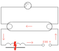
- Figure 1 shows the schematic structure of a fluorescent lamp connected to a bimetal starter and a choke coil. The starting process here is as follows: After switching on, the full mains voltage is applied to the starter because there is no current flowing through the lamp.
- Figure 2 The glow lamp that is integrated in the bimetal starter ignites and heats up.
- Figure 3 The bimetal strip bends when the glow lamp heats up, so that both contacts are short-circuited. The glow discharge goes out. A large current now flows through the heating coils (electrodes) in the fluorescent lamp and the choke coil. The filaments begin to glow and emit electrons that enrich the gas in the lamp with charge carriers.
- Fig. 4 The now missing glow discharge causes the glow lamp in the starter to cool down, as a result of which the bimetal contact opens again. Since the glow lamp and the not yet ignited fluorescent lamp together have a high resistance , the current in the choke coil drops quickly (the closed bimetal contact has bridged the glow lamp, as both are connected in parallel). The resulting self-induction briefly creates a high voltage (600 to 2000 volts), which ignites the gas in the lamp, which is enriched with charge carriers. The current now flows through the ionized gas in the lamp, it lights up.
Since the lamp is operated with alternating current, when the bimetal contact is opened, the current in the choke may be too low to build up the necessary ignition voltage. Then the starting process starts all over again in that the glow discharge ignites again and heats the bimetal. As a result, the start is usually a bit irregular, and the lamp often flickers once or twice before it starts.
After ignition, the operating voltage is divided between the lamp and the choke so that sufficient voltage (between 50 and 110 volts ) is maintained to keep the lamp glowing. It is too low for the glow lamp in the starter, and no further ignition takes place. This voltage is now sufficient to trigger a further ignition process in the lamp after every change in direction of the current, since the gas is sufficiently ionized and the electrodes are heated.
Defects
The service life of starters is limited. Due to the relatively high currents during the start-up process, the gas filling of the glass body is contaminated by sputtered metal. Due to the excessively high operating voltage of such starters, starting processes take longer and longer or do not take place at all.
In addition, the bimetal electrodes of the glow lamp can weld or the interference suppression capacitor can break down.
Since the fluorescent lamp itself is subject to similar aging processes, it can no longer be ignited at the end of its service life. In this case, the starter will also be destroyed after a while by the repeated start attempts. On the other hand, a defective (short-circuited) starter can destroy the heating wires of the fluorescent tube. Either these burn out or the alkaline earth oxide coating on the electrodes evaporates. The voltage drop across the electrodes increases and the fluorescent substance at the ends of the tube is covered (recognizable by the blackened ends). Both reduce the efficiency or even prevent the tube from igniting. The latter can also be done for only one flow direction, the lamp then flickers at half the frequency (instead of 100 Hz with 50 Hz) and with pronounced dark phases (instead of 3 to 4 ms with 14 to 15 ms).
Fuse quick starters , which are colloquially referred to as lightning starters , trigger an integrated thermal-mechanical fuse (second bimetal switch) after several unsuccessful ignition attempts (approx. One minute), so that no further start attempts are made. As a result, the lamp does not continue to flicker at the end of its service life, as is the case with a conventional starter. The fuse can be reset by pressing a (mostly red) button.
Single / tandem operation
One differentiates between starters for single mode (single lamps from 4 to 65/80 W) and starters for the so-called tandem operation (dual light , usually with two lamps at 18 watts, which are connected with a 36-watt choke in series). A starter for single operation cannot be operated in a tandem lamp - the glow lamp contacts only close after several minutes or not at all. A tandem starter can, however, be used in single lights up to a power of 22 watts. High power lamps cannot be reliably ignited in tandem if the sum of their operating voltages is well above half the mains voltage - the lamps would flicker continuously. If a defective lamp can no longer be ignited, glow starters will experience a permanent glow discharge due to the missing fuse. The contacts of the glow lamp close, and after an unsuccessful ignition attempt they open briefly and then close again. This leads to permanent flickering of the fluorescent lamp. It only ends when either a heating wire (an electrode) in the lamp burns out or the starter reaches the end of its service life due to the relatively large currents during the ignition process.
Electronic starters


In the illustrated embodiment of a relay-controlled starter, the choke current required to ignite the fluorescent lamp is determined by the varistor V1 and the resistor R1. When the capacitor C1 has reached the switching threshold of the miniature relay (C1 = 47 µF) after the second positive half-cycle of the mains voltage supplied via the choke at the latest, the ignition capacitor C2 is connected to the choke or the electrodes of the fluorescent lamp with an optional damping resistor R2. After their ignition, V1 blocks electrode voltages of a maximum of 120 volts and the ignition circuit from C2, R2 and the damper diode D2, which protects the electrolytic capacitor , is opened again. Since a lower choke current, which flows in only one half-wave direction, can be provided for the ignition process via D1, V1 and R1 compared to the glow starter, the use of this starter circuit for fluorescent lamps with a nominal output of more than 40 watts is not without problems. The ignition, which is only initiated with a special capacitor C2, which, strictly speaking, has to be matched to the inductor inductance, takes place after no more than four successive half-waves plus the relay switching time of a maximum of 20 ms.

In the circuit example of a thyristor starter, the thyristor TY2 is blocked and TY1 is switched through via the resistor R1 after the supply voltage has been applied. The current to be provided in the choke for the ignition process is largely determined by R2. After C1 has reached the switching threshold of TY2, TY1 is switched off and the ignition voltage is generated with the aid of C2 and the other self-capacitive component in the fluorescent lamp circuit. The resistor R4 ensures that TY2 remains switched on during lamp operation and that the ignition switch TY1 is therefore not made conductive again. This resistance does not apply to designs for TY1 in which switching operations below a certain anode-cathode potential - which here must be above the maximum operating voltage of the fluorescent lamp - are definitely excluded even in the case of a gate current to be switched through. Since R2 is chosen to be considerably smaller than R3, the diode D2 causes C1 to discharge quickly enough after the fluorescent lamp has been switched off. Various industrial component manufacturers for thyristor starters refer in their application illustrations to full-wave rectification in the starter branch and place two serially connected power diodes in parallel with R2. Since the voltage drop across both diodes, the special thyristor called "Fluoractor" and a mostly further diode on its cathode, is negligibly small compared to the supply voltage, the choke is subjected to a considerably higher current than the specified relay starter version, which depends on its technical dimensioning , but can at least potentially mean a reduction in their magnetic energy provided for ignition. The further and, in practice, greater disadvantage of industrially presented thyristor circuits is that the electrode heating is already effective below approximately half the supply voltage, i.e. in an area where reliable ignition of the lamp has not yet taken place and therefore unnecessary thermal wear of the electrode coil is assumed can be. This results in a not inconsiderable disadvantage compared to the relay starter, which can in principle show its functional advantages when the choke can make its sufficient energy contribution for the ignition process even with a relatively small pre-excitation current.
Compared to the classic glow starter, more complex circuit concepts for electronic starters are more reliable and also switch off the lamp in the event of a fault, but do not have to be reset. When designed as a soft starter, they significantly extend the service life of the lamp, especially in applications with many switching processes (e.g. light control with motion detectors ). There are two ways to start an electronic starter:
- Soft start: The cathodes are preheated using alternating current as with conventional starters. The cathodes glow slightly. After a short time of 1 to 3 s, depending on the model, the starter opens, creating a high induction voltage in the choke, which ignites the lamp.
- Quick start: The choke current is rectified, which means that it is higher than conventional starters due to the saturation of the choke. The starter therefore opens and ignites within half a second. A disadvantage of this second method is the noise of the throttle: If this is mounted on metal, a very loud humming noise can be heard during the start-up phase. If this type of preheating is not ended very quickly due to a defect in the electronic starter, the fluorescent lamp would be seriously damaged in a very short time.
Electronic ballasts (EVG) manage the starting process themselves.
If a fluorescent lamp no longer ignites, the choke (very rarely) or one of the cathodes can be defective in addition to the starter - this interrupts the circuit, the lamp no longer shows any glow (neither glow nor glow or flickering - see the circuit diagrams below for this ).
If one of the cathodes becomes deaf during operation, current only flows through the lamp during one half-wave; the starter will now try to ignite again, since the lamp has a rectifier effect due to the failure of mostly only one electrode. In this case, too, the lamp must be replaced in good time.
Operation with electronic ballast (EVG)


The arrangement of conventional ballast and starter can be replaced by an electronic ballast, usually these are resonance converters . The picture shows the structure for a compact fluorescent lamp ("energy saving lamp"). Together with the filter capacitor ( electrolytic capacitor , large upright cylinder), the rectifier (small black component with the imprint " + - " above the capacitor) generates a direct voltage. The two upright bipolar transistors to the left of the filter capacitor convert it into a high-frequency alternating voltage of around 40 kHz, which is connected to a resonance transformer (choke marked "3.5 m H " and one of the capacitors (4.7 nF ) in the rectangular plastic housing) Fluorescent lamp as a load is driving. The small transformer , consisting of a ferrite core with 2 × 3 and 1 × 5 turns, is used to control the half-bridge made up of the two transistors. Electronic ballasts integrated into the lamp housing usually contain a built-in fuse .
The fluorescent lamp is ignited after prior preheating by setting the clock frequency of the half-bridge to a value that controls the series oscillating circuit into resonance, which leads to a high voltage of around 1000 V across the lamp, which ignites the fluorescent lamp. After ignition, the impedance of the lamp drops to its operating value, as a result of which the operating voltage is set on the lamp.
The advantages over the conventional ballast are, depending on the design:
- almost no reactive power (devices with power factor correction )
- lower power loss in ballast and lamp (savings of up to 30%)
- reliable and quick start
- Flicker-free operation without stroboscopic effect, therefore can also be used on rotating machines
- Error detection and shutdown in the event of a defective lamp
- lower noise development (no mains hum )
- adaptive voltage adjustment, e.g. B. 154 to 254 V = with emergency power operation and 220 to 240 V ~ with normal network availability.
- Operation with low voltage (for example 24 V or 12 V). These electronic ballasts can also be operated on accumulators and are therefore suitable for use in vehicles, on boats or in allotments.
The disadvantage is the approx. 4 percent reduction in luminous flux.
The effective power loss of an electronic ballast for a 58 watt fluorescent lamp is less than 2 watts (compared to conventional ballasts: 8 to 13 watts). Another energy saving , the so-called HF gain, is achieved through the better average conductivity of the plasma: by operating with high frequency (50 kHz) instead of mains frequency (50 Hz), there are no phases in which the ionized atoms interact with the free electrons recombine and result in a poorly conductive plasma.
To assess the energy consumption TOE as other electrical appliances in energy efficiency classes divided the Energy Efficiency Index (EEI). The EEI takes into account both the power consumption of the ECG and the light output of the lamp. Within this classification, good electronic ballasts achieve class A2 . The efficiency of an electronic ballast can reach up to 95 percent.
Dimmable electronic ballasts can vary the lamp current in order to achieve brightness control (e.g. 3 to 100 percent brightness ) of the lamp. If the brightness is lower, the power consumption of the ECG is equally lower, which means that dimmable ECG can be classified in EEI class A1 under certain circumstances . With digital electronic ballasts, the constant stand-by consumption is detrimental to economic efficiency.
Conventional ballasts are found in the CELMA energy classification under C or D again. Ballast coils with a massive copper content or an optimized iron core are classified as 'low-loss ballasts' (VVG) and can be classified in energy efficiency class B1 or B2 .
Current developments show magnetic ballasts with lower losses than known from electronic ballasts. These ultra-low-loss ballasts are also more easily recyclable.
An electronic ballast is slightly more expensive than a comparable conventional ballast, but the lower energy consumption and the increased service life of the lamps usually result in significantly greater cost savings. On the other hand, electronic ballasts have a significantly shorter lifespan than the ballast (approx. 50,000 hours). Furthermore, according to the EU Directive 2000/55 / EG, ballasts with the energy efficiency classification C or D may no longer be brought into free trade since November 2005. Furthermore, the higher operating frequency together with the afterglow of the fluorescent phosphor layer reduces the dark phases when the voltage crosses zero, which is why the amplitude of the brightness fluctuations is also reduced compared to 50 Hz operation.
Adapter for converting to T5 lamps with electronic ballasts
Older luminaires with conventional ballasts for T8 fluorescent lamps can be converted to shorter T5 lamps with a lower output using adapters with clip-on electronic ballasts. These electronic ballasts are plugged in as an adapter set on one or both sides (connected or disconnected) between the lamp and the old lamp socket. When retrofitting, the conventional series reactor remains in the circuit (as an ohmic resistor with low power loss). The starter of the conventional luminaire is replaced by a jumper (same design, but short-circuited connections, some with microfuse) when retrofitting.
The electronic ballast required for operating T5 lamps enables flicker-free operation. Depending on the manufacturer, the potential savings are up to approx. 50 percent of the electricity costs; at the same time, the luminous flux (= brightness ) also decreases to a similar extent. These adapters reduce the effort required to convert the luminaires to a higher level of energy efficiency; no electrician is required. Due to the ban on T8 / KVG systems in April 2010 (see energy label ), this can represent an alternative to a complete conversion or replacement. 400 million lamps are said to be in use in Germany , well over 50 percent of which are still T8 or T12 with KVG.
Such conversions can be useful where large quantities of fluorescent lamps put a heavy load on the power grid due to their reactive power, mostly large shops in rural areas. If new lights are installed, there may be bottlenecks in the power supply. Since the reactive power is to decrease by 99% after the conversion and the active power by more than 50%, in some cases considerable power is available for further use. This can be a great advantage in areas with limited network capacity.
Compared to T8 lamps, T5 lamps require a higher ambient temperature for their maximum luminous flux (T5 requires approx. 35 ° C, T8 requires 25 ° C), which is advantageous due to the T5 lamp's self-heating. In cool environments, however, systems with a cladding tube are useful. This loss can possibly be compensated for by using high-quality mirror reflectors. There are also adapters that offer high savings potential through throttled operation, but with which the light output is well below that of a T8 lamp.
There are basically systems with a passive and an active side. These systems only heat one filament of the lamp before the start and then make a so-called rapid start. This is not in itself covered by the standard for ballast for fluorescent lamps. Other systems have a warm start on both sides and thus have the option of performing the soft start with a lower ignition voltage. The filaments of the lamps age noticeably less, the black ends stay off. ECGs equipped with this technology (a prerequisite is, among other things, a cable connection between both ends) then also have the option of receiving an ENEC test mark (tested luminaire component). It makes sense to contact the test center directly, e.g. B. to check with the VDE or the TÜV whether the corresponding adapter has a test seal. For example, there are adapters on the market that advertise with a VDE mark, which, however, only relates to safety and not to its function as a ballast. Depending on the type of circuit, the systems also have the option of increasing the power with active power factor correction filters in the input. This means that a 35-watt T5 lamp (then operated at 38) is almost as bright as a 58-watt T8 lamp, which with a CCG and starter usually consumes around 71 watts. However, the T5 lamps are operated outside of their specification, which greatly reduces their service life.
Concerns about using conversion adapters
Normally, luminaires for T8 (T26) fluorescent lamps produced by all luminaire manufacturers are not intended and tested for the use of T5 (T16) lamp adapters. This is clearly documented on the nameplate and, if available, on the equipment label with information on the lamp and its output. If other illuminants are used subsequently instead of the intended lamp, this is not the intended use of the luminaire and is therefore no longer the responsibility (guarantee and product liability) of the luminaire manufacturer. The manufacturer's responsibility for the luminaire affected by the conversion is transferred to the person responsible for the conversion. A renewed manufacturer identification and conformity assessment according to the applicable German and European guidelines is mandatory after the conversion. In addition to the problems discussed below, technical problems repeatedly occurred with some models offered on the market, which have repeatedly led to sales bans by the Federal Network Agency or to prohibition orders by the authorities. The ZVEI industry association also generally warns against using some adapters. Manufacturers of lamps and luminaires also advise against using them. Metrological examinations in Switzerland do not prove the retrofitting to make sense.
Cold cathode lamps
Cold cathode lamps (also CCFL from cold cathode fluorescent lamp ) are not fluorescent lamps in the usual German usage - they count among the fluorescent tubes . Cold cathode lamps are basically constructed like hot cathode lamps, except that there are no heating wires here - the electrodes instead consist of sheet metal sleeves.
Without preheating, the flow of electrons between cathode and anode in these lamps can only be achieved by using a higher voltage than hot cathode lamps. The ignition voltage is also higher. The reason is the so-called cathode fall - a high field strength is required directly at the cathodes in order to release electrons from them. Compared to hot cathode lamps, this leads to a lower degree of efficiency, but avoids heating and coating of the electrodes and thus enables simpler, more cost-effective manufacture. The service life is also considerably longer, since the wear and tear of the electrodes does not impair the function in contrast to the hot cathode lamp.
Cold cathode lamps have been used for neon advertising and as backlight for liquid crystal displays (LCD).
Cold cathode lamps for mains operation used to be operated with stray field transformers , which on the one hand generated the high operating voltages (5 to 10 kV) required to operate several lamps connected in series and, on the other hand, limited the operating current through their leakage inductance, similar to a choke.
Today and with direct current sources (e.g. notebook ) inverters ( inverters and resonance transformers ) are used, which generate the high voltages electronically. There are inverters with ferrite transformers and inverters with piezoelectric transformers . The latter work according to the piezo effect and have been developed for notebooks.
Replacement of fluorescent lamps with LED tubes
Induction lamp
properties
Light color


In contrast to incandescent lamps, fluorescent lamps do not have a continuous color spectrum . There is a choice of around a dozen colors, including many different variants of white. Roughly dividing the white fluorescent lamps in warm white (Engl. Warm white ), neutrally / cool white (Engl. Cool white ) and daylight white (Engl. Day light on). In many applications, the neutral white lamps are a good compromise, the cold white or daylight-like lamps have advantages when daylight is at the same time, whereas the warm white lamps are more compatible with incandescent lamp light. Fluorescent lamps with standard fluorescent materials ( halophosphates ) have, in addition to the advantage of a low price, the major disadvantage of poor color rendering and a relatively low light yield . The three-band fluorescent lamps are significantly improved in terms of color rendering and the luminous flux achieved . Here, the phosphor coating consists of a mixture of three phosphors that show relatively sharp-band emissions in the red, green and blue areas of the visible spectrum and whose spectra add up to white light according to the principle of additive color mixing in the lamp. So-called full-spectrum fluorescent lamps have the best color rendering - this is where the least amount of color distortion occurs. The spectrum is similar to daylight and almost as continuous. This is achieved by using at least four different phosphors (five-band fluorescent lamps).
The color rendering of lamps is described by the color rendering index .

The color composition of the light in fluorescent lamps is essentially determined by the composition of the coating on the glass, but also to a certain extent by the primary emission lines of the gas filling and their passage through the fluorescent material and the glass. The phosphor coating consists of crystalline powders (predominantly inorganic oxides) which, in the case of three-band phosphors, contain traces of divalent or trivalent lanthanoid cations that produce different colors depending on the lanthanoid used and the host lattice system on which it is based. These colors additively result in the luminous color of the lamp. The standard phosphors are based on calcium halophosphate with the general formula Ca 10 (PO 4 ) 6 (F, Cl): Sb, Mn, the different color temperatures being achieved by varying the concentration of the two doping elements manganese (Mn) and antimony (Sb).
The color temperature depends on the room temperature. Ordinary fluorescent lamps are designed for a room temperature of around 20 ° C, at this room temperature they heat up to just under 35 ° C. If the temperature falls significantly below this, the argon begins to glow more strongly and the fluorescent lamp emits more infrared light. There are special fluorescent lamps for low ambient temperatures for outdoor applications and in cooling systems. When it is very cold (around −25 ° C), street lighting with fluorescent lamps has a significantly reduced brightness.
The light color of the lamps is important for the quality of living . The light colors are also assigned to the various work tasks or workplaces. According to DIN 5035, white light is divided into three color temperature ranges:
| abbreviation | designation | Color temperature | application |
|---|---|---|---|
| ww | Warm white / warm white | <3300 K | Conference u. Offices, guest rooms, living rooms |
| nw | Neutral white / cool white | 3300-5300K | Schools, offices, workshops, showrooms |
| partly | Day light | > 5300 K | Daylight substitute in closed rooms and for technical applications |
The color “nw” is chosen most often. The same light color should always be used in a room. The manufacturers use a color number system with 3-digit numbers, where the first number indicates the color rendering quality. An 8 means an R a value from 80 to 89, a 9 means an R a value from 90 to 100. The last two digits indicate the color temperature in Kelvin if you extend them by two zeros. For the living area, for. B. the color number 827 or 930 can be selected. 840 is common in the office, with 854, 865 or even 880, according to some studies, supposed to lead to increased performance, since the light is more like daylight and accordingly contains more blue components.
From a purely technical point of view, fluorescent lamps with a color rendering index below 80 should be considered obsolete. However, lamps with the color codes 640 and 740 are still used in many municipalities to illuminate public spaces, as they are available at a lower price than three-band lamps with the code 840. Due to the demand, there is therefore no reason for the lighting industry for the time being to stop production. Only the light color 530 is becoming increasingly rare on the market. The following colors are available (the names of the light colors come from the Osram catalog and may vary from other manufacturers, but the numbers are standardized):
| code | Designation (Osram) |
properties | application | ||
|---|---|---|---|---|---|
| Colour reproduction | Luminous efficiency (lm / W for T8, 36W) |
additional | |||
| 530 | Basic warm white / warm white |
bad (typically Ra = 58) | moderate | Warm light. Objects appear brownish and little contrasted. | Garages, kitchens. Now rare - in favor of colors 827 and 830. |
| 640 | Basic neutral white / cool white |
moderate | moderate (79) | Cooler work light | Used very often. Offices, work rooms, train stations, outdoor lighting. Should be replaced with 840 lamps. |
| 740 | moderate | moderate | |||
| 765 | Basic daylight / daylight |
moderate | bad (69) | Bluish daylight substitute | Especially in offices or behind advertising posters. Should be replaced by 865 lamps. |
| 827 | Lumilux interna | Well | very good (93) | Incandescent light | Living rooms, bedrooms, children's rooms. |
| 830 | Lumilux warm white / warm white |
Well | very good (93) | Halogen lamp-like light | Almost like 827, slightly more blue. In northern Germany as street lighting. |
| 835 | Lumilux white / white |
Well | very good (93) | White light | A little cooler than the 830 - for kitchen or outdoor lighting, for example. Rarely in West Germany. |
| 840 | Lumilux neutral white / cool white |
very good | very good (93) | White work light | Offices and public buildings, outdoor lighting. In Northern Europe, many people find it too cool for living spaces. |
| 865 | Lumilux daylight / daylight |
very good | good (90) | Daylight substitute | Allegedly performance-enhancing work light. Offices and outdoor lighting. |
| 880 | Lumilux skywhite | Well | moderate (81–84) | Blue light that corresponds to a cloudless sky. | Melanopically effective lighting: influencing circadian rhythms , activation |
| 930 | Lumilux Deluxe warm white / warm white |
outstanding | moderate (75-78) | Warm light | Living rooms in which color should be accentuated. |
| 940 | Lumilux Deluxe neutral white / cool white |
outstanding | moderate (78–81) | Cool work light | Workplaces where color accents are important. Museums, galleries. |
| 950 | / Colorproof daylight daylight |
excellent also: full spectrum color rendering (97–98) |
moderate (78) full spectrum color rendering: poor (64–65) |
Daylight substitute | Museums, galleries, aquarium lighting. Full spectrum color rendering: printing industry, photo labs, graphic industry. |
| 954 | Lumilux Deluxe daylight / daylight |
outstanding | moderate (79) | Daylight substitute | Museums, galleries, aquarium lighting. |
| 965 | Lumilux Deluxe daylight / cool daylight |
excellent also: full spectrum color rendering (98) |
moderate (78-79) full spectrum color rendering: poor (58) |
Daylight substitute | Museums, galleries, aquarium lighting. Slightly cooler than 954. Full spectrum color reproduction: printing industry, photo labs, graphic industry. |
A fluorescent lamp with the requirement of a color rendering of more than 90 (class 1A) loses significantly more light output in the lower color temperature range than in the higher one. A lamp with three-band fluorescent materials of color 840 and 36 watts of power achieves a luminous flux of approx. 3350 lumens (Osram Lumilux T8). The corresponding lamp in color 940 (Lumilux De Luxe) achieves 2900 lumens, the lamp in color 954 around 2850 lumens, and that of color 930 only around 2700 lumens.
- Colored fluorescent lamps

Fluorescent lamps and energy saving lamps are u. a. Also available in one color (red, yellow, green, blue) for decoration purposes. This is achieved by varying the fluorescent phosphor . See also: LHGL tub .
The black light lamps also work with a fluorescent substance ( europium -doped strontium fluoroborate or tetraborate for 370 nm or lead-doped barium silicate for 350 nm) to convert the mercury line in UV-B into the UV-A range. These lamps have a glass tube doped with nickel oxide to absorb visible light> 400 nm.
- Linguistic differentiation from neon tubes
Fluorescent lamps or tubes are sometimes incorrectly referred to colloquially as neon tubes , which were historically developed as the first type of fluorescent tube. A (technically real) neon tube is only filled with neon in its pure form , which glows orange-red and - in contrast to fluorescent lamps - has neither mercury vapor nor fluorescent material on the inner glass wall. The glass tube with a diameter of only 1 to 2 cm can be clear or red in color, does not come in standard sizes and is not exchanged by users themselves because of the high operating voltage. With other gases, mostly noble gases and gas mixtures, rarely with the addition of some mercury vapor, sometimes also with the use of a fluorescent coating, other, in particular strong colors, but also white are achieved.
Energy efficiency
Fluorescent lamps achieve a luminous efficacy of around 45 to 100 lumens per watt (for comparison: normal incandescent lamps: around 10–15 lm / W) and thus have a comparatively high energy efficiency ; this is exceeded by sulfur lamps (95 lm / W) and sodium vapor lamps (150 lm / W) - with a poorer color rendering index - and metal halide high-pressure discharge lamps (approx. 95 lm / W). Modern LEDs also achieve a higher efficiency than fluorescent tubes (> 100 lm / W).
Fluorescent lamps save around 70 to 85% energy compared to incandescent lamps. In measuring equipment, new fluorescent lamps are only aged 100 to 200 hours , the measurement only takes place around 10 to 20 minutes (depending on the type) after they have been switched on.
All fluorescent lamps only reach their higher operating pressure after they have been heated up and therefore only reach their full luminosity after a few seconds to minutes. This effect can be observed more clearly with compact fluorescent lamps , since they work with higher operating pressures and temperatures. Particularly at very low ambient temperatures and without a surrounding luminaire housing, the luminosity of fluorescent lamps is sometimes significantly lower than at room temperature. For this reason, special cold-resistant fluorescent lamps are used for lighting outdoors or in cold rooms, which still work at low ambient temperatures. The maximum and the typical yield of these special lamps is well below that of normal, highly efficient fluorescent lamps. LED lamps that do not show any loss of efficiency are predestined for these applications today. There are similar efficiency disadvantages with full spectrum fluorescent lamps; Their special phosphor composition enables - at the expense of efficiency - a high color rendering index of over 90.
The luminous efficacy of fluorescent lamps, which is around four to six times higher than that of incandescent lamps, is offset by a larger volume, higher purchase price and the delay in reaching full brightness.
lifespan
Fluorescent lamps are characterized by a very long service life, which is limited by the adsorption of the mercury on the lamp components, the decomposition of the fluorescent material and the service life of the hot cathodes .
Conventional fluorescent lamps (T8, halophosphate) have a real useful life of 6000 to 8000 hours on a conventional ballast. A modern fluorescent lamp (T5 and T8, tri-phosphor) achieves a useful life of 15,000 hours on the VVG and up to 25,000 hours on the ECG, special versions even up to 80,000 hours. A compact fluorescent lamp usually has a useful life of between 5000 and 15,000 hours. After this time, the lamps emit less than 80% of the original luminous flux. Newer phosphors allow operation until the cathodes fail, since they still deliver 80 ... 90% of the original luminous flux.
To achieve the nominal service life, it is recommended that fluorescent lamps operated with dimmable electronic ballasts be burned in at full power for 100 hours before dimming in order to stabilize the cathode coating.
In order to achieve a long service life, fluorescent lamps should be switched as little as possible. When starting, the cathodes must preheat (warm start), since a cold start (ignition of the lamp discharge with cold cathodes) greatly reduces the service life. This is more reliable with electronic ballasts than with conventional ballasts and glow starters. The nominal service life is determined with a switching cycle of 3 hours (165 min on, 15 min off). An exception are newer types of energy-saving lamps, which are designed for several 100,000 switching operations instead of a few 10,000 by controlling the preheating phase.
Compact fluorescent lamps with integrated ballast (so-called energy-saving lamps) often fail due to failure of the electronic ballast; this is often sensitive to increased ambient temperatures, which leads to early failures, especially in closed luminaires.
Flicker and strobe effect
Due to the mains frequency (50 or 60 Hz), the lamp light goes out with conventional ballasts in the area of each zero crossing. There are light-dark phases in a 100 or 120 Hz rhythm ( flickering ), which can cause stroboscopic effects that are noticeable during fast movements or that, in rotating machines, simulate a slow or stationary machine. The flicker also leads to faster fatigue. An improvement is the duo circuit or, in large systems, the supply of three-phase alternating current (three-phase current), whereby several lamps emit their light out of phase.
Electronic ballasts (also the clip-on ECGs that are offered for converting T8 luminaires with conventional ballasts to T5 lamps with a lower output) can provide almost flicker-free light, as they operate the lamp with alternating current of a higher frequency (typically 45,000 Hz ). The resulting high-frequency fluctuation in brightness (90,000 Hz) cannot be perceived by the human eye, especially since it is still attenuated by the afterglow of the phosphor. However, depending on the quality and design of the electronic ballast, the mains frequency can more or less modulate the amplitude of the high-frequency current , so that a remainder of the 100 or 120 Hz flicker remains. This applies above all to compact fluorescent lamps with integrated, mostly inexpensive electronic ballasts with a smoothing capacitor that is too small . This can also dry out relatively quickly due to the high ambient temperature in the lamp base, especially if it is suspended.
Aspects of environmental protection
Environmental protection and recycling
The mercury in fluorescent lamps is toxic to humans and the environment, as is the coating (phosphor and cathode coating) of the lamp. When destroyed, mercury and dust containing pollutants are released immediately; other substances are released when they decompose or burn and sometimes form even more toxic decomposition products, aerosols or gases. In addition, the materials used, europium , tin and copper, are relatively expensive and some can be recovered. For these reasons, since March 24, 2006, used fluorescent lamps may not be disposed of with household or residual waste.
Within the EU, the recycling of fluorescent lamps and other light sources is regulated by the WEEE Directive, which was implemented in Germany by the Electrical and Electronic Equipment Act . Fluorescent lamps from private households must be handed in to a collection point ( waste material collection center , recycling center ) or to dealers who are legally obliged to take them back. The regulation for fluorescent lamps from the commercial sector differs in the individual EU member states . In Germany, the lighting manufacturers have founded Lightcycle Retourlogistik und Service GmbH , a non-profit organization , which operates the nationwide take-back logistics for used lamps (gas discharge and LED lamps) and sends the collected old lamps for professional recycling . Normal household quantities from small businesses can also be disposed of via the public collection points, which are also looked after by Lightcycle.
The required mercury content per lamp has been continuously reduced over the course of its development. Since a large part of the mercury is lost through adsorption on the glass, the electrodes and the fluorescent material, older lamps in particular had to contain a larger supply of mercury (several tens of milligrams). The reduction in the amount has been made possible by protective layers of glass and fluorescent material. The lead content of soldered connections, especially in lamps with integrated ballast, was a recycling problem and has been reduced to almost zero by the RoHS guidelines . Other pollutants contained in fluorescent lamps are small amounts of barium, strontium and antimony as well as halogenated flame retardants (plastic parts of energy-saving lamps ).
Electrosmog and electromagnetic compatibility
In principle, fluorescent lamps and the luminaires designed for them, like all other commercially available electrical devices, must meet limit values for electromagnetic compatibility . This is documented by the CE mark affixed to the devices . This means that interference emissions are limited to a level at which the impairment of other devices is acceptable (because it is minor or brief). Also guaranteed by CE, the lamps must be robust against interference from the mains supply. These are tests with typical interference pulses (so-called burst , typical for the consequences of switching processes in the network, and surge , typical for the consequences of lightning strikes) that the devices must withstand. KVG are naturally hardly susceptible to this.
The following listed malfunctions caused by the luminaire are possible:
- Fluorescent lamps with electronic ballast generate broadband high frequency through the inverter located in them , some of which is emitted by the lamp and its leads. The decisive factor is the working frequency , which is usually just below 50 kHz, and its harmonics (harmonics).
- Fluorescent lamps with conventional ballast also emit a broadband interference spectrum, primarily in the frequency range of AM broadcasting. Among other things, radio reception on long , medium and short wave is disrupted .
- The starting process of conventional fluorescent lamps can also have a disruptive effect on audio systems - the broadband interference pulse generated spreads on the power lines and mostly reaches the signal lines and amplifiers capacitively in various ways. The most effective measure against this and also against the broadband interference during operation is the so-called local interference suppression in the luminaire ( capacitor in the glow starter) or a line filter in front of the luminaire or the disturbed consumers.
- Occasionally, light generated by electronic ballasts interferes with the IR receivers of the remote control of entertainment electronics devices, as their operating frequencies are similar.
Electrosmog is a colloquial term that includes non-ionizing radiation ( radio waves ) and electrical and magnetic fields and their postulated health impairments. Conventional ballasts in particular generate a magnetic stray field with a frequency of 50 Hz. The effects of electrosmog on health are highly controversial.
Partial sales ban in the EU
Like incandescent lamps, certain fluorescent lamps are also affected by the sales ban in the EU. The ban is regulated in EC regulation 245/2009, which serves to implement the Ecodesign Directive 2005/32 / EC and comes into force in three stages:
In the first stage since April 2010, minimum values for the luminous efficacy and color rendering of T8 and T5 lamps have been in effect; less efficient lamps of these types may no longer be placed on the market. At the same time, manufacturers must publish detailed technical information on all lamps. From the second stage since April 2012, the values also apply to all other twin-socket lamps (e.g. T10 and T12), which means a de facto ban on T12 lamps. At the same time, requirements for service life and the decrease in luminous flux during operation came into force. The third stage calls since April 2017 that all fluorescent lamps with ballasts of energy efficiency class A2 must be compatible.
Similar bulbs
Because of their similar design, line lamps are often mistaken for fluorescent lamps. Line lamps do not generate light by gas discharge, but by a filament, so they are incandescent lamps .
literature
- A. Senner: Electrical engineering. 4th edition. Verlag-Europa Lehrmittel, Wuppertal 1965.
- Hans R. Ris: Lighting technology for the practitioner. 5th edition. VDE-Verlags GmbH, Berlin / Offenbach 2015, ISBN 978-3-8007-3617-1 .
- Günter Springer: Expertise in electrical engineering. 18th edition. Verlag-Europa Lehrmittel, Wuppertal 1989, ISBN 3-8085-3018-9 .
- Ernst Hörnemann, Heinrich Hübscher: Electrical engineering specialist training in industrial electronics. Westermann Schulbuchverlag GmbH, Braunschweig 1998, ISBN 3-14-221730-4 .
- Osram: ECG for T5 lamps, technical primer. Munich 2005, online version (PDF) , accessed on November 25, 2012
- Conversion to LED: Conversion of a T8 G13 fluorescent tube - with starter according to E DIN 62776: 2012-02.
Web links
- Things to know about the use of fluorescent lamps in offices etc.
- Which color codes mean what? - Explanation of the color codes
- Light colors from fluorescent lamps
- Fluorescent lamps as backlights in television studios
Individual evidence
- ↑ History on infrasite-griesheim.com
- ↑ Light guide (PDF; 163 kB) of the City of Hamburg , p. 3.
- ↑ a b c d e ГОСТ IEC 60400: 2011 . In: Скачать ГОСТ . 2013 (Russian, egfntd.kz [accessed November 11, 2019] Russian harmonized IEC standard for lamp sockets).
- ↑ DIN EN 60081 (2006-05) . Beuth Verlag, 2006.
- ↑ DIN EN 60901 (2008-09) . Beuth Verlag, 2008.
- ↑ Zentralverband Elektrotechnik- und Elektronikindustrie eV: Radiological assessment of starters for fluorescent lamps with a filling gas containing Kr-85 , on Energieverbrauch.de
- ↑ http://www.st.com/web/en/resource/technical/document/datasheet/CD00000866.pdf accessed on January 31, 2015.
- ↑ THE FLUORACTOR® Y1112FLUORESCENT LAMP STARTER SWITCH , on bourns.com, accessed on January 31, 2015.
- ↑ THE FLUORACTOR Y1112L FLUORESCENT LAMP STARTER SWITCH ( Memento from February 4, 2015 in the Internet Archive ) accessed on January 31, 2015.
- ↑ See functional description of the state of the art in European patent EP0552687B1 http://patentimages.storage.googleapis.com/pdfs/5f6e671cc53f26e23b82/EP0552687B1.pdf accessed on February 4, 2015.
- ↑ Palmstep: http://www.palmstep.com/html/de/starter/index.htm accessed on January 31, 2012.
- ↑ Osram: Dimmable ECG for fluorescent and compact fluorescent lamps (KLL) - QUICKTRONIC INTELLIGENT DALI DIM. ( Memento of February 2, 2012 in the Internet Archive ) Retrieved January 31, 2012.
- ↑ Vossloh-Schwabe: ( page no longer available , search in web archives: VS A2-VVG-Starter-System ) accessed on January 31, 2012.
- ↑ Enerlux: ULTRA LOW LOSS ENERGY SAVING. ( Memento of June 27, 2010 in the Internet Archive ) Retrieved January 31, 2012.
- ↑ Helvar: Archived copy ( Memento of the original from December 18, 2007 in the Internet Archive ) Info: The archive link was inserted automatically and has not yet been checked. Please check the original and archive link according to the instructions and then remove this notice. , accessed January 31, 2012.
- ↑ Be careful with T5 adapters for T8 lights. ( Memento from January 28, 2012 in the Internet Archive ) ZVEI, September 2006.
- ↑ Do T5 adapters for T8 luminaires ensure safe and standardized light? (PDF; 191 kB) (No longer available online.) ZVEI, March 2006, archived from the original on January 12, 2012 ; Retrieved February 11, 2010 . Info: The archive link was inserted automatically and has not yet been checked. Please check the original and archive link according to the instructions and then remove this notice.
- ↑ OSRAM statement on T5 conversion adapters. (PDF) (No longer available online.) Osram, November 2008, p. 15 , formerly in the original ; Retrieved February 11, 2010 . ( Page no longer available , search in web archives )
- ↑ SFOE (PDF) , requested on February 2, 2012.
- ↑ hereinspaziert.de three-band light colors
- ↑ a b c d e f g h i j k l m n o Light can be white, white, white or white. (PDF) Light color and lumen overview. Osram, August 2008, accessed on February 27, 2014 .
- ↑ a b c d Product overview - lamps, ballasts, lights - Germany, Austria, Switzerland - spring 2012. (PDF) Philips, December 2011, p. 25 , accessed on February 27, 2014 .
- ↑ LUMILUX T8 - L 36 W / 880. Osram, accessed on February 27, 2014 .
- ↑ a b c d e Product overview - lamps, ballasts, lights - Germany, Austria, Switzerland - spring 2012. (PDF) Philips, December 2011, p. 30 , accessed on February 27, 2014 .
- ↑ a b c d Product overview - lamps, ballasts, lights - Germany, Austria, Switzerland - spring 2012. (PDF) Philips, December 2011, p. 31 , accessed on February 27, 2014 .
- ↑ OSRAM COLOR proof: The first fluorescent lamp for absolutely correct color balance. (PDF) Osram, September 2009, accessed on February 27, 2014 .
- ↑ Brief data of the LED type XLamp XP-G2 from Cree cree.com
- ↑ Brief data of the LED array type NSB066A from Nichia nichia.co.jp
- ↑ https://www.assets.lighting.philips.com/is/content/PhilipsLighting/fp927853283601-pss-global Data sheet for F32T8 / ADV835 / 2XL / ALTO II 28W 30PK (fluorescent lamp Extra Long Life T8) from Philips Lighting Holding BV , accessed July 11, 2018.
- ↑ Technical application guide Double-capped fluorescent lamps: T8, T5 HE and T5 HO, T5 short and single-capped fluorescent lamps: T5 FC Part 1: Products and Technology (PDF), page 110, accessed on July 11, 2018.
- ↑ Megaman: Product page for ingenium technology. ( Memento of September 10, 2012 in the web archive archive.today ) accessed on January 13, 2009.
- ↑ Osram: Product page of the Osram Dulux EL Facility. ( Memento of March 7, 2009 in the Internet Archive ). Retrieved January 13, 2009.
- ↑ T. Jüstel: Low Pressure Discharge Lamps (PDF) (seminar documents of the Münster University of Applied Sciences ), p. 31ff, accessed on June 11, 2018.
- ↑ Regulation (EC) No. 245/2009 (...) environmentally friendly design of fluorescent lamps without built-in ballast, high-pressure discharge lamps as well as ballasts and lights for their operation (...) , accessed on July 16, 2009
- ↑ List and table of all fluorescent lamps affected by the EU sales ban ( Memento of the original from October 29, 2009 in the Internet Archive ) Info: The archive link was automatically inserted and not yet checked. Please check the original and archive link according to the instructions and then remove this notice.