
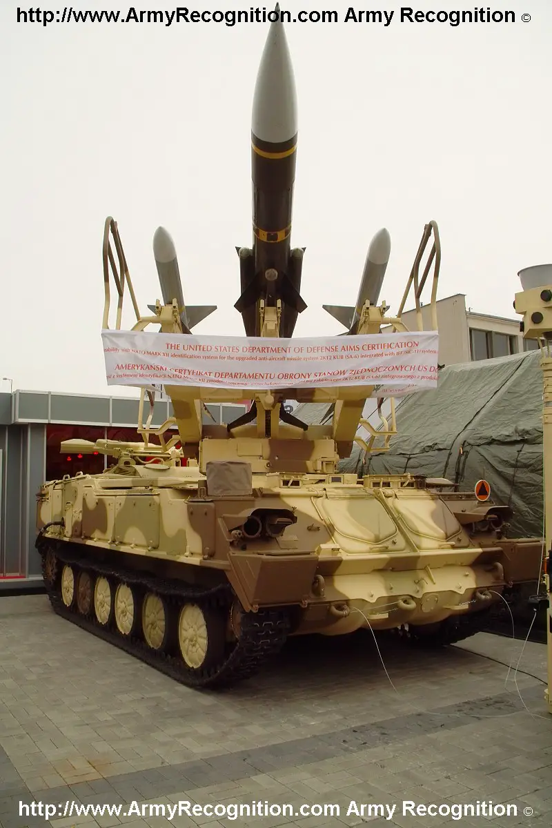
2K12 cub

2K12 "Kub" ( Russian Куб Würfel , NATO code name : SA-6 Gainful ) is a Soviet anti-aircraft missile system . The export version 2K12 "Kwadrat" with limited combat options (Russian: Квадрат - square) is also called SA-6 Gainful by NATO .
The 2K12 "Kub" weapon system is a medium-range mobile anti-aircraft missile system. The development began in the late 1950s, the introduction to armament in 1967. The weapon system was used to protect armored and motorized rifle divisions in attack, defense and on the march.
development
At the end of the 1950s it became apparent that existing anti-aircraft guns like the S-60 could no longer follow the tank and motorized rifle units on the battlefield. The protection of these systems against enemy weapons was also limited, the range and height of fire were not sufficient to combat modern jet aircraft . At the same time, advancing technical development made it possible to build smaller and thus more mobile anti-aircraft missile systems.
Development began on July 18, 1958 in the test design office OKB-15 GKAT (Russian: ОКБ-15 ГКАТ ), a branch of the Central Design Office ZKB NII-17 (Russian: ЦАКБ НИИ-17 ). The task was to combat air targets with a speed of 420 to 600 m / s and an altitude of 100 m to 7 km with an effective combat distance of up to 20 km. The probability of destruction should be at least 0.7.
Testing of the system began in 1959 at the Dongusk (Донгузск) firing range. On February 18, 1963, the first air target was successfully fought as part of the testing with an Il-28 . Overall, however, the testing continued until 1966. After overcoming various technical difficulties, the system was approved for use in armament on January 23, 1967. In the same year series production began in Ulyanovsk , Sverdlovsk and Dolgoprudny .
construction
Structure of the weapon system
The weapon system was normally used as a closed unit in an anti-aircraft missile regiment or an anti-aircraft missile brigade. The regiment or brigade consists of four to six anti-aircraft missile batteries, a command battery and a technical battery.
An anti-aircraft missile battery of the system consists of:

- a reconnaissance and control station 1S91 (Russian: 1С91)
- four launch ramps 2P25 (Russian: 2П25)
- two transport and loading vehicles 2T7 (Russian: 2T7)
- a booth to receive the destination assignment (KPZ) 9S417 (Russian: КПЦ 9С417)
- 18 anti-aircraft missiles 3M9 (Russian: 3M9)
- as well as an armored personnel carrier ( BRDM-2 or BTR-60 ) as a reconnaissance and command vehicle.
The lead battery consists of:

- a UAZ452T survey vehicle
- a booth for transmitting the automated target assignment (KBU) 9S416 (Russian: КБУ 9С416)
- a vehicle for centralized fire control FuKS
- a panoramic station RBS-40 ( P-40 , Russian П-40 )
- a height finder PRW-16 (Russian ПРВ-16 )
- a panoramic station RBS-15 ( P-15 , Russian П-15 ) or a panoramic station RBS-19 ( P-19 , Russian П-19 )
- a panoramic station RBS-18 ( P-18 , Russian П-18 )
The technical battery consists of:

- Missile transport vehicles 9T22
- Transport and loading vehicles 2T7 (Russian: 2T7)
- various inspection and test vehicles, cranes and other equipment.
The command battery was responsible for clearing up the airspace and assigning targets. The anti-aircraft missile battery was responsible for the immediate combat of the air target. The technical battery was responsible for the assembly, refueling, control and delivery of further anti-aircraft missiles.
Interaction of the elements of the weapon system
In the control battery, a common air situation picture is created in the cabin to transmit the automated target assignment or in the vehicle for centralized fire control . For this purpose, the signals from the various radar stations are brought together on several display devices. The use of several radar stations operating in different frequency bands made it possible to cover a large area and increased protection against passive and active radar interference. The radar stations working in the meter wave range also facilitate the reconnaissance of aircraft with stealth properties. If the different radar stations are used alternately, reconnaissance and combat by the enemy is also made more difficult.
The air targets to be combated are selected by the fire control officer (military: the shooter, usually the regiment commander) of the regiment and marked on the viewing device with a light pen. From the cabin for the transmission of the automated target assignment , the target coordinates are transmitted by means of radio data transmission to the cabin for receiving the target assignment of the anti-aircraft missile battery. The transformation of the coordinates takes place there . These are then coded by wire (NVA radio) and transmitted to the reconnaissance and control station 1S91 .
This target specification is displayed in the 1S91 and after confirmation by the '1S91' commander, the antenna of the target escort radar is automatically directed at the selected aerial target. The specified target coordinates are encrypted and transmitted to the start ramps 2P25 via a wire line or radio data transmission . The rocket is aimed at the calculated lead point, the antenna of the homing head of the rocket at the air target. This data is determined on the basis of analog computers in each '2P25' separately. The choice of the number of missiles to be deployed and their launch can be made in the command battery , in the reconnaissance and control station 1S91 or in the launch ramp (only missiles can be switched off in the launch ramp, but the number cannot be influenced). (?)
The reconnaissance and control station 1S91 has the option of independent airspace reconnaissance. This enables the battery to be used independently and reduces the time it takes to prepare for combat , since all the locations of the elements involved no longer have to be measured. When deployed as part of a division, however, there is a risk of unwanted multiple or non-combat against air targets. The reconnaissance range is also much smaller, which leads to shorter reaction times. The long-term radiation of the radar device also increases the risk of detection by the enemy.
All '1S91' and '2P25' units have an autonomous power supply based on an integrated gas turbine.
Steering method
The weapon system works with a semi-active method. For this purpose, the air target must be illuminated by the continuous wave radar immediately before take-off until it hits the guided missile or the missile motor burns out. In a semi-active procedure, in contrast to command guidance, the number of missiles that can simultaneously attack a target is theoretically unlimited. The use of more than three missiles on an air target increases the probability of hits with the 2K12 only insignificantly. Since the exhaust gas jet of a rocket is strongly ionized and the energy reflected back from the target is very low (approx. 0.1 nW), the target is also covered for subsequent rockets, so the use of more than three rockets was not intended.
The method of proportional approximation is used. The rocket is not guided directly to the air target, but to a calculated, variable lead point. If the probability of a hit is sufficient, this leads to a lower lateral acceleration of the rocket during flight, which enables the construction of a lighter rocket.
KPZ 9S417 / KBU 9S416
The fire control complex K1 ( GRAU index : 9S44 "Krab") was originally developed for the fire control of the weapon system S-60 and the anti-aircraft missile complex S-75 . He was also used for the anti-aircraft missile complex 2K11 Krug .
Up to three radar stations can be connected to the KBU 9S416 , but only the air position of one radar station can be carried out on the two viewing devices; the switchover was done manually. The simultaneous escort of up to ten air targets is possible, two of which can be assigned to the different anti-aircraft missile batteries at the same time. The side angle, target distance and target height of the selected aerial targets are transmitted to the KPZ via data link. In addition, the reciprocal transmission of up to 24 additional signals, such as operational readiness and operating mode of the anti-aircraft missiles, is possible. However, accurate target assignment is only possible if the locations of the corresponding radar station, the KPZ , the KBU and the reconnaissance and control station are correctly measured. The target height, the lateral angle and the distance to the target are calculated in the KPZ . Digital computers with ferrite core memories and a clock frequency of 6.5 kHz are used in both cabins, but the values determined are displayed in analog form.
Airspace with a radius of 300 (KBU) or 200 km (KPZ) can be displayed on the viewing devices, the maximum altitude of the targets is 30 or 51 km, their maximum speed 1000 or 1575 m / s. Overall, air targets at a distance of 15 to 160 km could be recorded and assigned. By using the complex K1 9S44, the upper limit of the extermination zone can be raised to 11,000 m. Since the reconnaissance stations of the anti-aircraft missile batteries do not emit at all and the target tracking radars only emit briefly, the risk of reconnaissance by the enemy is reduced. The use of encrypted radio data instead of voice radio for guidance increases the security against eavesdropping and interference.
The time to take up a position is 18 minutes for the KBU, 9 minutes for the KPZ, and the time to leave the position is 22 or 6:30 minutes. The unfolded cabins can be brought into full combat readiness within 5:30 or 5 minutes.
Reconnaissance and control station 1S91


The reconnaissance and control station 1S91 is used for reconnaissance of the airspace, target acquisition and escort as well as illuminating the target during the flight of the guided missile. It is also the command point of the anti-aircraft missile battery.
The station consists of
- the base vehicle GM568
- of the power supply system 2Ä6
- the extension and leveling mechanism 2Ä8
- the reconnaissance station 1S11 (NATO code name: Straight Flush) with the identification device 1S51
- the target companion and highlighting station 1S31 (control station) and the television sight 9Sch33
- the telecode device 1S61
- of the TNA-3 surveying facility
- two radios R-123 and the on-board intercom R-124
- the nuclear weapon protection system
The crew consisted of a total of four soldiers (commander (head radio locator / platoon leader / battery chief), (head) radio locator 1, radio locator 2, (tank) driver).
The base vehicle GM 568 was developed from the vehicle family of the SPW-50 and the floating tank PT-76 . The launch pad 2P25 and the Fla-SFL ZSU-23-4 also use a chassis from this vehicle family. It is powered by a W-6 diesel engine with 280 hp. A maximum speed of 50 km / h and a driving range of 300 km is achieved. The total weight of the station is 21.5 t.
The on-board network is fed by the power supply system 2Ä6 with alternating current 220 V / 400 Hz and direct current 27 V. The systems of the 1S91 have a power consumption of around 60 kW. Power can be supplied from the stationary network via converters, a PÄS-100 diesel generator, the traction motor or a gas turbine installed lengthways in the rear. The consumption of the gas turbine is 80 l / hour, but the advantages here are the rapid preparation for combat and the low power-to-weight ratio .
The extension and leveling mechanism is used to extend the lower, cylindrical container that carries the antenna of the reconnaissance station 1S11 and to align the entire station horizontally.


The reconnaissance station 1S11 is used for all-round reconnaissance . This is a pulse radar with two identically structured transmit and receive channels. The reconnaissance distance is 3 to 65 km, the altitude range 30 to 7000 m. With a pulse repetition frequency of 2 kHz, pulses lasting 0.5 microseconds are emitted. The resolution according to the lateral angle is 1 ° in the first and 45 'in the second channel, the resolution according to the elevation angle in both channels is only 20 °. The station cannot determine the exact flight altitude, it is only assigned to one of two altitude ranges. The radar works in the G / H band (transmission frequency in the range 4 to 8 GHz). The transmission power is 500 +/- 50 kW in the first and 600 kW in the second channel ( pulse power ). Magnetrons are used in the transmitter . The sensitivity of the receiver is 10e-13 W. For the suppression of passive radar interference with a coming vacuum memory tubes operating system for the selection of moving targets (SBZ) with wind compensation applied. Active radar interference can be masked out by regulating the sensitivity of the receiving channels , wobbling the pulse repetition frequency or changing the transmission frequency.
The different performance data are based on the antenna construction. A trimmed parabolic mirror is used in the 1S11 . Both channels are fed by three radiators each, the energy distribution in the first channel is 1: 1: 1, in the second channel 2: 3: 5. In principle, this is a phased array antenna that produces a directional diagram in the form of a coscan function. The target data are displayed on a PPI scope . To assign targets, markers on the screen are brought into line with the air target using handwheels, while the antennas of the 1S31 are aligned with the air target . When using the 9S44 system , the marks are automatically displayed based on the target data transmitted, but must be readjusted manually.
The friend-foe identification system 1S51 is part of the Kremnij 2 complex . The operating principle is based on sending and receiving a coded pulse train. A total of twelve manually changeable code filters are available. The antenna of the 1S11 is used, the feed takes place via dipoles on the left and right of the feed of the 1S11 . From the end of the 1980s, the conversion to the more modern Parol identification device began ; in the NVA, however, the conversion no longer took place.


The target escort and lighting station 1S31 consists of a pulse train radar for target tracking and a continuous wave radar for target lighting. Both devices work in the cm wave range and use the same parabolic antenna. The transmitter and antenna are housed in or on the upper extendable, cylindrical container. The station can accompany targets up to a distance of 45 km and an altitude of 30 to 7000 m. In the destination support station , the monopulse difference method is used for destination support . There are two identically structured channels with a transmission power of 200 kW (pulse power). The continuous wave transmitter has an output of around 500 W, the frequencies are changed by manually replacing quartz filters. This frequency change is the only protection of the continuous wave radar against interference, therefore operating data and usable frequencies are subject to the strictest confidentiality. In peacetime this transmitter is only put into operation in specially shielded halls for maintenance purposes. Due to the use of the monopulse difference method, the pulse train radar is resistant to angular response interference; Against other interferences, the wobbling of the pulse repetition frequency, an automatic system for the suppression of noise interferences, a system working with potential storage tubes for the selection of moving targets (SBZ) and the change of the transmission frequencies can be used. The target data is displayed on two screens (angle and distance separately). In order to take over the target, markers are displayed on both screens that must be brought into line with the air target.

The 9Sch33 television sight allows you to accompany aerial targets without radar radiation up to a distance of 45 km. In this case, the distance to the target is determined by the 1S11. However, due to the steering method used, this distance information is only required once before the start. To enable reconnaissance even when there is backlight, the television visor has three optical filters that can be changed at the push of a button. The target is displayed on a television screen, the sight is controlled manually using a joystick . When viewed from the front, the camera is located on the right below the antenna of the 1S31 . It is swiveled together with this antenna.
The 1S61 telecode device transmits the guide values to the start ramps via a data link . At the same time, the operating parameters of the launch ramps are transmitted to the reconnaissance and control station. The data can be transmitted via radio or wire. In order to minimize alignment errors, the position of the start ramps in relation to the reconnaissance and control station 1S91 must be precisely determined.
| Technical data 1S11 | |
|---|---|
| Frequency range | G / H band |
| Pulse repetition time | |
| Pulse repetition frequency | 2 kHz |
| Transmission time (PW) | |
| Reception time | |
| Dead time | |
| Pulse power | 2 × 500/600 kW |
| Average performance | |
| displayed distance | 65 km |
| Distance resolution | approx. 70 m |
| Opening angle | 45 '/ 1 ° (horizontal) |
| Hit count | |
| Antenna round trip time | 15 (20) |
Start ramp 2P25


The launch pad transports and launches the anti-aircraft missiles. It consists of:
- the base vehicle GM578
- the power supply system with gas turbine 1Ä5
- the system of steering, connection and control
- the artillery section 9P12
- the gyro navigation device TNA-3
- the telecode device 1S61
The base vehicle GM578 based as GM568 on the construction of the SPW-50 , the performance data are similar.
The power supply system has an output of 40 kW at a voltage of 220 V / 400 Hz alternating voltage and 27 V direct voltage. The power supply is also possible here from the stationary network via converters, a PÄS-100 diesel generator, the traction motor or a gas turbine installed lengthways in the rear.
The system of control, connection and control essentially consists of the commander's desk 9BM2, the start block 9S323 and the control block 9W320. The system is switched on at the commander's block, an automatic function check is carried out, the parallax (in this context the term parallax is used to represent the displacement between the two elements that requires a coordinate transformation) is set between 1S91 and 2P25 and the prohibited sectors for shooting are entered. The start block is used to control the start sequence, the control block to check the homing head of the anti-aircraft missile. Other elements establish the connection between the systems installed in the vehicle and the 9P12 artillery unit .
The artillery part 9P12 accommodates the anti-aircraft missiles and enables side and height pointing. The side straightening range is unlimited. The aiming of the rockets at the calculated lead point takes place automatically. From the artillery part, commands are transmitted to the missile as well as feedback from the missile - readiness of the missile, detection of the target by the homing head. To do this, it is connected to the rocket by two cables that are sheared off during launch.
The TNA-3 gyro navigation device is used to determine one's own position during the march and to determine the parallax to the reconnaissance and control station .
In contrast to the 1S91, the 1S61 telecode device only had one antenna.
3M9 missile


The rocket was developed in the OKB-134 GKAT from 1959 . The 3M9 was the first anti-aircraft missile that was developed in this design office. With the semi-active steering and the ramjet engine , technical innovations were used. At the same time, the K-13 air-to-air missile based on the American AIM-9 Sidewinder was developed in the design office. The overall situation led to various problems and long delays. The state testing planned for 1960 had to be postponed, the head of the design office was replaced in 1961. During testing in 1963, only a third of all rockets could be launched successfully. It was not until 1965 that the solid fuel engine was operationally safe.
Several variants of the rocket have been developed: 3M9M, 3M9M1, 3M9M2 and 3M9M3. The 3M9MÄ variant was based on the 3M9M and was intended for export. With the 3M9M1 variant, decisive innovations were introduced, which contributed to a considerable increase in the combat value of the entire weapon system. From the 3M9M1 it was possible to overshoot the reconnaissance and control station . This made it possible to introduce new combat orders for the anti-aircraft missile battery such as semicircle and square, which made better use of the area and made visual reconnaissance by the enemy more difficult. For the first time, targets could also be fought in the recovery process, until then it was only possible to fight on the opposite course. Finally, detection in the air was also possible: the continuous wave transmitter was only switched on after the rocket had been launched, which significantly reduced the transmission time and minimized the enemy’s opportunities for reconnaissance and combat. However, these missiles were not exported to all user states.
The rocket is constructed from front to back as follows: The homing head (2) with the parabolic antenna (1) of the receiver is located under a plastic ballistic hood . This receives the signals from the continuous wave transmitter of the 1S31 reflected by the target . To acquire the air target , the rocket is switched to target mode while still on the launch pad . It can remain in this operating mode for 10 minutes and after a break of 60 minutes for another 5 minutes. Since the diameter of the antenna used is relatively small, the result is a relatively broad directional diagram. For the first detection of an air target, the error that occurs is too large, so that the frequency shift of the reflected signal resulting from the speed of the air target must also be used. As a result, the early versions of the missile had difficulties in detecting slow-flying airborne targets such as helicopters. After the first acquisition, however, the width of the directional diagram no longer plays a role, since only the change in the side and elevation angle is evaluated. The swivel range of the antenna is 150 °. This means that even heavily maneuvering air targets can be reliably accompanied.
This is followed by the two-channel radio detonator 3Ä27 (3). It triggers the warhead (4) about 30 m from the target.
The 3N12 warhead consists of the fragmentation warhead, the explosive charge and the ignition device. The total weight is 57 kg. The housing and explosive charge are designed in such a way that, in conjunction with the radio detonator, an optimal shape of the fragment cloud results.
The autopilot (5) calculates the steering commands for the rudder of the missile on the basis of the signals transmitted by the homing head.
A pressure vessel (12) is located behind the autopilot. The compressed air in it drives a turbine to power the rocket during flight. This pressure vessel is filled with compressed air in the technical battery. The compressed air is also an energy source for the electropneumatic rowing machines.
At the approximate height of the pressure vessel there are four rudders (11) arranged in a cross shape, the steering commands of which are calculated by the autopilot.
The 76 cm long as a ramjet designed cruise engine 9D16K (7) has a diameter of 29 cm and used as a combustion chamber, the burnt-start engine (8). It contains a 67 kg pyrotechnic gas generator LK-6TM with the composition 65% by weight magnesium , 25% by weight sodium nitrate and 10% by weight naphthalene . The air required for combustion is fed in via four air inlets (6) located at the height of the rudder. Since the gas generator set contains only a small amount of oxidizing agent, the ramjet is lighter than a comparable rocket engine, which must already contain the oxygen required for complete combustion. The cruise engine burns for about 20 seconds.
The starting engine (8) with the thrust nozzle (9) is about 1.7 m long and has a mass of 172 kg. If it burns out for three to six seconds, it accelerates the rocket to a speed of Mach 1.5 . It is a solid rocket drive using the double-base propellant WIK-2 with the composition 56% by weight nitrocellulose , 39% by weight nitroglycerin , 5% by weight additives.
The tail stabilizers (10) have additional rudders for position stabilization and position sensors for the autopilot. Underneath the rocket is the shear device, which cuts the cables to the 9P12 artillery section when it is launched .
Transport and loading vehicle 2T7
_7.jpg)
The 2T7 transport and loading vehicle is used to transport three prepared anti-aircraft missiles and load the 2P25 launch pads . The carrier vehicle was initially a ZIL-157 truck , later a ZIL-131 . The rockets were loaded and unloaded with the aid of a hydraulic crane located at the rear.
variants
2K12
The complex 2K12 is the originally developed version.
2K12M1
With version 2K12M1 minor improvements were introduced. The speed of rotation of the reconnaissance station was increased from 15 to 20 revolutions / min, for example. The destruction zone has been enlarged, availability, reaction times, interference protection and hit probability improved. The development began in 1967, the introduction to the troops took place in 1972.
2K12M3
With the introduction of the 2K12M3 version , a decisive improvement was achieved, which was based primarily on the 3M9M3 rocket. Fighting targets in pursuit, the now possible overshooting of the 1S91 and, above all, the possibility of catching it in the air increased the combat value of the weapon system considerably. The introduction of this version began in 1976.
2K12M4
The 2K12M4 version uses elements of the 9K37 Buk anti-aircraft missile system . The main difference to the previous versions was the increase in the number of target channels. Each anti-aircraft missile battery could now fight two instead of just one air target at the same time. The introduction of this version began in 1978.
2K12 "square"
The 2K12 "square" was a special version for export to the Arab states and Romania . The 9Sch33 television sight was missing, in some cases a different friend-foe identification system was installed and the performance of other components was reduced. The resulting reduced combat opportunities became clear in June 1982 during the battle in the Bekaa plain , when Israeli troops were able to turn off 19 Syrian anti-aircraft batteries deployed there.
Modernizations
Various companies have presented designs for modernizing the technology, which is now over fifty years old. Since the fuel in the solid fuel rockets used oxidizes depending on the environment, they only have a limited shelf life of five to seven years. Then they have to be repaired. Since many user countries cannot or no longer have access to the corresponding technology, work is being carried out on replacing the existing missiles. In 2008, the Polish company WZU presented an adaptation of the AIM-7 Sparrow to the 2K12 system. The steering process remains unchanged. The Russian company Wympel has proposed an adaptation of its Wympel R-77 guided missile , which, unlike the original version of the 2K12, has an active radar system. The company NII, which emerged from the OKB NII, also presented modernizations of the weapon system in 2010.
Technical specifications
| Technical specifications | 2K12 | 2K12M1 | 2K12М3 | 2K12М4 | |
|---|---|---|---|---|---|
| Extermination zone, [km] | distance | 6-22 | 4-23 | 4-25 | 4-24 |
| height | 0.1-7 (12) | 0.08-8 (12) | 0.02-8 (12) | 0.03-14 | |
| Destruction probability |
Fighter plane (with an anti-aircraft missile) | 70% | 80-95% | 80-90% | |
| helicopter | - | - | - | 30-60% | |
| Cruise missiles | - | - | - | 25-50% | |
| Maximum speed of the air target (m / s) | 600 | 600 | |||
| Response time, [s] | 26-28 | 22-24 | 24 | ||
| AA missile speed, [m / s] | 600 | 700 | 700 | ||
| Weight of the rocket, [kg] | 630 | 630 | |||
| Weight warhead, [kg] | 57 | 57 | |||
| Number of target channels per battery | 1 | 2 | |||
| Number of reception channels per missile | 2-3 | 3 | |||
| Time for transition from marching to combat position of the battery, [min] | 5 | ||||
| Number of guided missiles per launch pad | 3 | ||||
| Year of introduction in the Soviet Army | 1967 | 1973 | 1976 | 1978 | |
Operational principles
The 2K12 weapon system was intended for air defense within the framework of a tank or motorized rifle division. Each of these divisions had an anti-aircraft missile regiment. The air defense was supplemented by anti-aircraft batteries assigned to the armored or motorized rifle regiments, which were equipped with the Fla-SFL ZSU-23-4 and the anti-aircraft missile systems 9K31 Strela-1 and 9K35 Strela-10 . In addition there were the portable anti-aircraft missile systems 9K32 Strela-2 and their successors used at company level . The 2K11 Krug system was used at the higher-level management level .
The 2K12 weapon system was basically used within the framework of the anti-aircraft missile regiment. However, it was also possible to use individual batteries - if the reconnaissance range was limited.
Due to the technical design, it was not possible to fire from a short stop or while moving. The anti-aircraft missile battery moved into a firing position that had to be around 400 × 400 m, relatively flat and free of obstacles. When using the automated fire control as part of the regiment, the firing position had to be measured, i.e. the coordinates of the location of the reconnaissance and control station had to be known relatively precisely. From an unmeasured firing position, the battery was only able to work on the basis of its own reconnaissance by the 1S11 . In order to evade enemy reconnaissance and weapon action, a change of position was mandatory after the launch of anti-aircraft missiles. In the position, the reconnaissance and control station was in the middle, the launch ramps roughly square at the corners. Alternatively, the launch ramps could be unfolded in a semicircle around the reconnaissance and control station if the approach direction of the enemy was known. The rigid handling of these rules of engagement meant that the FlaRak batteries were very easy to identify from the air. Together with the technical restrictions already described and the unwillingness of the Syrian troops to change positions, this contributed significantly to the high losses in the Bekaa plain in 1982. After that, further battle orders were developed, but these only represented minor variations of the square and semicircle battle orders. Only with the overshooting of the 1S91, which was possible from version M3, the 1S91 no longer had to be at the center of the battle rules . The standard time to take up a position was 9 minutes and to leave it was 5:45 minutes. The standard time for switching on and for the functional check was 5:30 minutes, the time from target assignment to launch of the rocket was 54 seconds.
The regiment was basically deployed in two lines. In the attack, the front line of the anti-aircraft batteries was about 5 to 10 km, in defense 3 to 5 km behind the own troops. The distances between the batteries were about 15 km. An area with a radius of 15 km was covered by a battery, the coverage zones of the individual batteries consequently overlapped. The change of position took place in overturning action.
The high mobility of the weapon system and the high level of protection of the crews and vehicles against the effects of enemy weapons in comparison to western weapon systems were advantageous. The automated fire control and the resulting increased reconnaissance range were also advantageous. The biggest weak point from the start was the limitation to one target channel per firing battery. As part of the division to be supported, only four to six air targets (depending on the number of batteries in the regiment) could be fought simultaneously by the 2K12 . The space requirement for the positions was also problematic when used in urban and cut terrain. Therefore, the 2K12 was replaced in the motorized rifle divisions from the mid-1970s by the 9K33 Osa system , the smallest tactical unit of which was the 9A33 start and control station . At the same time, the number of target channels increased significantly. Since tank formations were generally only deployed in terrain that was favorable to armor, the restrictions on the choice of positions were less severe. The 2K12 system therefore remained armed in the armored divisions as a rule. The replacement by the 9K37 weapon system was only started and completed in the Soviet Union / Russia.
States of operations

Current users
The weapon system is currently still in use in the following countries:
-
 Algeria
-
 Armenia
-
 Egypt
Egypt
-
 Bulgaria
-
 India
India
-
 Iran - at least eight launch ramps are said to have been handed over from Russia to Iran in 1995/96.
 -
 Croatia
-
 Cuba
Cuba
-
 Libya
Libya
-
 Mozambique
-
 Myanmar
-
 North Korea
-
 Poland
-
 Romania
-
 Russia - use as target system 3M20M3 Peniye
-
 Serbia - approx. 80 copies, modernized
 -
 Slovakia
-
 Syria
Syria
-
 Czech Republic
-
 Hungary
-
 Vietnam
Former users
Former users are:
It is characteristic that despite the old age, the weapon system has not been replaced by successor types, except in Russia.
Planned users
![]() Israel Israel tried in 1991 to obtain 2K12 Kub from the former NVA for test purposes, but the illegal transport was discovered by the water police and triggered the tank affair .
Israel Israel tried in 1991 to obtain 2K12 Kub from the former NVA for test purposes, but the illegal transport was discovered by the water police and triggered the tank affair .
Use in the GDR
In the National People's Army , the weapon system was used from 1976 in the anti-aircraft missile regiments of the troop air defense . To this end, the anti-aircraft missile divisions of the armored and motorized rifle divisions were restructured into anti-aircraft missile regiments. The equipment was not uniform, the anti-aircraft missile regiments (FRR) 7 and 9 had five anti-aircraft missile batteries (these regiments belonged to tank divisions), the other regiments assigned to motorized rifle divisions (MSD) only (FRR-1, -4, -8, -11) four batteries . In 1984 the FRR-8 ( 8th MSD ), from 1987 the FRR-11 ( 11th MSD ) was converted to the 9K33 weapon system . The existing 2K12 of these regiments were handed over to the reserve divisions . The inventory of anti-aircraft missiles was probably around 1200 pieces. Almost all rockets were destroyed by the Buck company or, after its bankruptcy, by the Nammo-Buck company in Pinnow and the remains were disposed of. The Pinnow repair shop was responsible for the main repair of these missiles until 1990.
Use in wars and armed conflicts
Yom Kippur War 1973
SA-6 systems played a role above all in the Middle East conflict and surprised the Israeli air force in the 1973 Yom Kippur War , after they had only got to know the older S-75 and S-125 Neva before. The highly mobile 2K12 posed a considerable threat to the Israeli Douglas A-4 and also the F-4 Phantom II . The situation was exacerbated by the fact that the Israeli radar warning receivers did not indicate that the 2K12's radar systems were being illuminated . Only a reprogramming of the radar warning receiver and a change in tactics could defuse the situation. Israel admitted more than 40 losses from anti-aircraft missile systems, with the 2K12 proving to be the most effective system. Israeli pilots named the 2K12 , based on the appearance of the rockets on the launch pad, Three Fingers of Death .
Lebanon War 1982

In the Lebanon War, the Syrian troops also used 2K12. However, in Operation Mole Cricket 19 , the Israeli Air Force managed to destroy large numbers of 2K12, S-75 and S-125. The positions had already been cleared up beforehand by unmanned drones. The Israeli Air Force used such drones as bait in the operation. After the launch of the anti-aircraft missiles, the positions were destroyed by the use of AGM-45 Shrike and AGM-78 Standard ARM . The operation was supported by the use of E-2C and Boeing 707 as ECM aircraft . Syrian troops fired 57 missiles without getting a single kill.
Libya
Libya used the 2K12 in the fighting with Chad in the 1980s. The weapon system posed a threat to the French aircraft used on the Chad side. On January 7, 1987, however, a position was successfully destroyed by the use of an AS.37 Martel .
After taking the Ouadi Doum airfield , Libya had to leave a large number of weapon systems there. Most weapon systems were flown out immediately to the United States and France , but a few 2K12 ended up in the hands of Chad. On March 30, 1987, Libya had to evacuate the bases in Faya Largeau and Aouzou. As a result, Libyan Tupolev Tu-22s were commissioned to bomb and destroy the technology that had been left behind. Ironically, on August 8, 1987, one of two bombers used near Aouzou was shot down by one of the captured 2K12s. This incident led to the cessation of the Libyan air strikes.
Iraq
During the Second Gulf War , an American F-16 was shot down and a B-52G was damaged by 2K12 . Overall, the threat posed by the 2K12 was compensated for by electronic countermeasures, but the older S-75 and S-125 achieved a few kills.
Bosnia
An American F-16 was shot down over Bosnia in 1995 . A Croatian MiG-21 and two to three Croatian An-2s could also be shot down. The Bosnian minister Irfan Ljubijankić fell victim to a 2K12 as a passenger on a Mi-17 helicopter .
See also
literature
- AK Wostrikow, SM Dolotow, WG Krassik, AU Mitin: Basics of the structure of radio electronic systems for the guidance of anti-aircraft missile complexes. Ministry of Defense of the USSR: Publishing house of the Kiev Higher Anti-aircraft Missile School of Engineers, Kiev 1982.
- Richard A. Gabriel: Operation Peace for Galilee: The Israeli-PLO War in Lebanon. Hill and Wang, ISBN 0-8090-7454-0 .
- Benjamin S. Lambeth: The Transformation of American Air Power. (illustrated edition ed.), Cornell University Press, ISBN 0-8014-3816-0 .
- Kenneth M. Pollack, Arabs at War: Military Effectiveness, 1948-1991. Bison Books, ISBN 0-8032-8783-6 .
Web links
- FRR 11 - a military unit of the NVA that used the system
- Information about the weapon system from "Ракетная техника", (Russian) ( Memento from July 28, 2003 in the Internet Archive )
- Information about the weapon system "Kub" from "Вестник ПВО", (Russian)
- Photographs, (Russian)
Individual evidence
- ↑ NVA: four or five; for other countries of use and time periods, the structure and quantity structures may differ
- ↑ [1]
- ↑ http://www.palba.cz/portal.php?news=article&topic_id=1562&start=10&sid=416322592b4da7fa1adea16385e9ed19
- ↑ http://www.palba.cz/portal.php?news=article&topic_id=1562&start=10&sid=416322592b4da7fa1adea16385e9ed19
- ↑ Archive link ( memento from July 2, 2012 in the web archive archive.today ), Poland's WZU shows Sparrow-armed Kub ( page no longer available , search in web archives ) Info: The link was automatically marked as defective. Please check the link according to the instructions and then remove this notice. at Jane's Information Group website
- ↑ 2K12 Kub modernization for Polish Army at MSPO 2007 Defense Exhibition at MSPO 2007 Picture Gallery
- ^ RV-77 could create a smarter Kub at Jane's Information Group website
- ↑ Jane's missiles and rockets from January 5, 2010 ( Memento from July 2, 2012 in the web archive archive.today )
- ↑ a b c d e f with missile 3М9М3; with rocket 9М38 same values as with 9K37 "Buk"
- ↑ a b c d When using the K-1 system, for NVA in the literature different information
- ↑ other user countries later or not at all
- ↑ Soviet Army and NVA, in other user states partially anti-aircraft missile brigade
- ↑ Information for NVA, times for other countries of assignment may differ
- ↑ History of the KPAF (Russian), airwar.ru
- ↑ Peniye training target system ( Memento from January 17, 2010 on WebCite ) at Russian Firearms: Specifications, Photos, Pictures website
- ↑ Vympel 3M20M3 (Russian Federation), aerial targets at Jane's Information Group website
- ↑ 3M9ME Gainful SAM launch from TEL
- ^ Pollack (2002), p. 532
- ^ Matthew M. Hurley: The Bekaa Valley Air Battle. Archived from the original on September 23, 2008. In: Airpower Journal . No. Winter 1989, August. Retrieved September 10, 2008.
- ↑ Gabriel (1984), p. 98
- ↑ Lambeth (2000), p. 94
- ↑ Libyan Wars, 1980–1989, Part 6 ( Memento from April 25, 2011 in the Internet Archive )
- ↑ Airframe Details for F-16 # 87-0228.
- ↑ All For One. June 19, 1995, Kevin Fedarko and Mark Thompson for Time Magazine
- ↑ http://www.f-16.net/aircraft-database/F-16/airframe-profile/2880/ Airframe details for 89-2032.
- ^ AF Monthly, July 1992
| Shoulder supported |
9K32 Strela-2 | 9K34 Strela-3 | 9K310 Igla-1 | 9K38 Igla | 9K338 Igla-S | 9K333 Werba |
|
| Short haul |
9K31 Strela-1 | 9K33 Osa | 9K35 Strela-10 | 2K22 Tunguska | 9K330 gate | 96K6 Panzir | Sosna |
|
| Middle distance | ||
| Long-distance |
S-25 | S-75 | S-200 | S-300P | S-300W | S-350 | S-400 | S-500 |
|
| Sea-based |
9K32F Strela-2F | 9K34F Strela-3F | 9K310F Igla-1 F | 9K38M Igla-M | 4K33 Osa-M | 3K87 Cortic | 3K95 Kinschal | 3K96 Redut | M-1 Wolna-M | M-2 Volkhov | M-11 Schtorm | M-22 Uragan | 3S90 Esch | S-300F Fort | S-300FM Fort-M |