Propulsion methods for space travel
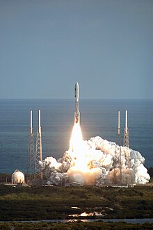
Propulsion methods for space travel are techniques for changing the speed of missiles (such as spacecraft ) to reach space and / or to fly in space. There are many different variants with numerous advantages and disadvantages, as well as with very different levels of technological maturity . Including technically almost fully developed methods that are in development and only theoretically proposed or simulated. The subject is the scene of current research as well as numerous popular scientific speculations.
The goal of a propulsion method is to provide delta v, i.e. change in speed of the spacecraft. Since very large distances have to be bridged in space travel, the speed of the spaceship should also be very high and thus also the specific impulse of the propulsion method. On the other hand, a drive method should also generate considerable acceleration force in order to keep the travel time as short as possible. This is especially important on manned missions.
Propulsion methods include the propulsion systems. The drive systems used today are exclusively recoil drives within the framework of Newton's third axiom . Of these rocket propulsion systems in practice , the most common are chemical propulsion systems ( thermal engines with combustion), which include solid and liquid propulsion units. There are also electrical and nuclear variants in the group of rocket engines, as well as versions with cold gas. Sometimes special flight maneuvers can be used to accelerate a spacecraft or to steer its flight path in a certain direction, e.g. B. a swing-by maneuver .
In the following overview article in the field of propulsion systems, as alternative concepts to rocket propulsion systems, launch and launch mechanisms , methods without fuel requirements and theoretical methods of propulsion systems are treated.
In addition to the main propulsion systems for accelerating the entire spacecraft, small thrusters are also used for maneuvering and attitude control.
need
In order to take a stable orbit around the earth, or another body, it is necessary to reach the first cosmic speed . Bodies in space themselves move on Kepler orbits . To change the orbit of a body, a change in speed is necessary. According to the Ziolkowski equation, this must be achieved by propulsion of a spacecraft:
Here is the change in speed, the effective outflow speed, the starting mass and the firing mass . The effective outflow speed results from the weight-specific impulse :
Here is the gravitational acceleration of the earth.
Since it is usually necessary to change orbit several times to reach a destination, a so-called delta-v requirement can be defined, which represents the sum of all speed changes that the propulsion of the spacecraft must achieve in order to reach the destination. As can be seen from the formulas, the specific impulse, which is dependent on the fuel, should be as large as possible in order to be able to keep the proportion of fuel in the starting mass as small as possible.
If the goal is not to reach an orbit around the starting planet, but to reach another celestial body, a spacecraft can also be accelerated by flight maneuvers such as swing-by (example: flight path of the Rosetta probe ).
Concepts for drive systems
The list is structured as follows:
-
Technological maturity level (TRL) / intended use
- “T” TRL 0–2: theoretical
- “E”; TRL 3–7: explored
- “F”; TRL 8–9: already flying
- Explanation and overview, details in the specialist article
- : approximate maximum specific impulse
- Thrust: approximate thrust range of the propulsion system in Newtons .
Gas drive
Inert gas is stored here under pressure. Pressure is one (or the only) energy source for fuel.
Cold gas drive
Use: position control (F)
With the cold gas drive, a gas that is often under high pressure, usually nitrogen , is expanded from a container through nozzles.
- : ≈ 40–120 s
- Thrust: a few µN to approx. 100 N
Solar thermal
Use: Drive (E)
With a solar thermal drive, two inflatable parabolic mirrors concentrate the solar radiation on a graphite block , through which hydrogen is passed, which is then heated to around 2800 Kelvin.
- : 900 s
- Thrust: 1–100 N
Lightcraft
Use: launch of small satellites (E)
The concept of the lightcraft is a kind of laser drive : the spacecraft receives energy for acceleration from a laser or maser located on the earth's surface . The beam hits a reflector and generates high temperatures there, which leads to the expansion of the fuel on the reflector; the expansion of the propellant transfers some of the momentum to the missile. When flying within the earth's atmosphere, the gases contained therein should be sufficient so that the missile's fuel is only necessary at greater heights. The concept is to be used for small satellites . The biggest obstacle at the moment is that the required laser power cannot be provided.
- : unknown
- Thrust: unknown
Chemical drives
Chemical drives get their energy from the exothermic reaction of chemical elements. The exhaust gases are then expanded through a Laval nozzle . Chemical drives are powerful, but have a low discharge speed compared to other drives.

Solid
Use: start, drive (F)
In the existing chemical variants, the solid rocket engine has the fuel in solid form, the fuel tank is also the combustion chamber. Solid propellants can be homogeneous or heterogeneous solids (composites) that contain other additives (stabilizers) in addition to the fuel and the oxidizer. For solid rockets, as are common in space travel, special pourable mixtures of ammonium perchlorate ( APCP ) or sodium or ammonium nitrate, aluminum powder, synthetic resin (polybutadienes, polyurethanes, etc. as a binding substance) and possibly small amounts of iron oxide are used as a catalyst. After casting, these mixtures result in a solid but plastic body (propellant), which greatly reduces the formation of cracks and cavities. Transport and handling are also very safe. Lithium, beryllium, boron or magnesium are increasingly being used instead of or in addition to aluminum.
- : 265 s
- Thrust: 1–1000 kN
Monergol
Use: position control, drive (F)
In monergolen liquid fuels is only one liquid component. Monergols are brought to disintegration by adding a catalyst, which is why the term hangover is permissible for monoergole. An example of a katergol is hydrazine , which is used, for example, for attitude control systems of spacecraft. Here, hydrazine is decomposed into nitrogen and hydrogen with the aid of a catalyst (aluminum oxide).
- : 222 s
- Thrust: 0.1-100 N

Monergole show i. d. Typically less efficient than Diergole, i.e. H. they need more fuel for the same Delta-V , but they can compensate for this with less complex systems and lower system mass (e.g. omission of the pump system for the second fuel component). Only on long missions that require a lot of fuel is this no longer enough.
Diergol
Use: position control, drive, start (F)
At Diergolen there are two components of the fuel that are stored separately. The fuel is pumped into a combustion chamber in a controlled manner immediately before the combustion process. There the substances react with each other.
- : 450 s
- Thrust: 0.1-1000 kN
Triergol
Use: drive, start (E)
Triergol systems (three-substance systems) contain diergol systems (two components), which are additionally supplied with hydrogen or metal powder (lithium, aluminum, beryllium) to increase the specific impulse. Although these fuel systems have been well studied, they have never been used in practice because of the complex engine and rocket structure that requires three tanks.
- : 500 s
- Thrust: 1–1000 kN
Hybrid missile
Usage: Drive (E), Start (F)
In hybrid rocket engines is both liquid before and solid fuel. Hybrid fuel (Lithergol) is a mixed drive made of a solid fuel, usually made of plastic, for example hydroxyl-terminated poly-butadiene (HTPB) or lithium hydride and a liquid oxidizer. This is usually nitric acid, liquid oxygen, nitrous oxide or a mixture of liquid oxygen and liquid fluorine ( FLOX ). The liquid fuel is fed to the solid in a controlled manner. This enables the engine to be controlled and switched off, which is not technically possible with pure solid rockets.
- : 420 s
- Thrust: 5–1000 kN
Breathing air
Usage: Start (E)
An air-breathing rocket engine is used to ascend from the earth's atmosphere. The advantage is that the oxygen in the air can be used as an oxidizer and does not have to be carried along. For high altitudes, however, an oxidizer must still be carried, as the oxygen in the air is no longer sufficient to operate the engine.
- : 450-2800 s
- Thrust: ≈ 300 kN
Allotropes
Use: start, drive (E)
Using the oxygen allotrope ozone as an oxidizer would increase the outflow velocity. However, since ozone is unstable, storage is very difficult, if not impossible. The allotrope Tetra oxygen should be more stable. This would allow specific pulses of up to 564 s in a vacuum.
- : 500-564 s
- Thrust: 1–1000 kN
Electric motors
Electric propulsion systems use electrical energy to propel a spaceship. This can be done by heating or ionizing the fuel (called support mass here). In general, electric drives are currently weak in thrust, making it impossible to take off from the surface of a planet. In order to achieve the highest possible performance, the energy supply must also be as large as possible. The energy can be generated by solar cells or radioisotope generators .
With satellite electric drives are widely used today; most new geostationary satellites use this type of propulsion.
Resistance heated engine
Use: position control, path control (F)
In the case of a resistance-heated engine, the fuel is heated by a resistor through which current flows. This can be a tungsten wire , for example , the principle is similar to that of an immersion heater .
- : 1000 s
- Thrust: 152 mN @ 1 kW
Thermal arc engine
Use: position control, path control, drive (F)
A thermal arc is formed between a cathode and an anode . The fuel flows through the arc , which is heated up considerably (approx. 5,000 K). The hot gas is then expanded through a nozzle. The thrust is only generated by the thermal effect of the expansion and not by magnetic fields (in contrast to the MPD).
- : 2000 s
- Thrust: 3.35 N @ 30 kW
Field emission engine
Use: position control (F)
The field emission thruster uses two very closely spaced plates between which a liquid metal ( cesium ) flows to the tip by capillary forces . The plates are positively charged. At a little distance from the tip there are two more plates that are negatively charged. The electric field between the two ionizes the fuel and accelerates it. This engine can be very weak and light.
- : 12,000 s
- Thrust: 1 mN @ 60 W
Ion thrusters
Use: position control, path control, drive (F)
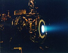
The radio frequency ion thrusters (RIT) generate a plasma using electromagnetic waves, and the positively charged particles are then accelerated outwards through grids. After passing the so-called neutralizer, which feeds electrons back into the beam and thus makes it electrically neutral, the particles are ejected. Xenon is used as a supporting mass . NASA's HiPEP falls into this category, as does the RIT from Germany.
- : 6000-9150 s
- Thrust: 600 mN @ 34.6 kW
Kaufmann engine
Use: position control, path control, drive (F)
The Kaufmann engine generates a plasma by means of an electric arc, and the positively charged particles are then accelerated outwards through grids. After passing the so-called neutralizer, which feeds electrons back into the beam and thus makes it electrically neutral, the particles are ejected. Xenon or mercury is used as fuel . NASA's NSTAR is one such engine.
- : 3100 s
- Thrust: 92 mN @ 2.6 kW
Hall drive
Use: position control, path control, drive (F)
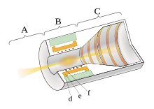
Hall effect thrusters consist of a ring-shaped acceleration channel through which a magnetic field passes through concentrically located magnets. There is a hollow anode at one end. An externally attached cathode acts as a source for electrons, which are accelerated by the potential difference to the anode and trapped in the strong magnetic field. In addition, there is an azimuthal drift due to the Hall effect . The neutral fuel is fed through the hollow anode and ionised by collisions with the trapped electrons. The electric field acting between the electrodes accelerates these ions so that they can be ejected at high speed. Electrons, which are also emitted by the cathode, act to neutralize the ion beam. Possible fuels are noble gases such as xenon , krypton or argon , but also metallic fuels such as bismuth , zinc or magnesium . A distinction is made between 2 types of Hall drives: SPT (Stationary Plasma Thruster) and TAL (Thruster with Anode Layer), which differ primarily in terms of materials and geometry. So far, SPT has mainly been used on numerous satellite missions, including a. also on the ESA SMART-1 mission .
- : 1640 s
- Thrust: 68 mN @ 1.2 kW
Magnetoplasmic dynamic engine
Use: path control (F), drive (E)
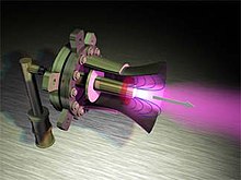
Magnetoplasmic dynamic thrusters (MPD) consist of a funnel-shaped anode with a rod-shaped cathode in the center. If voltage is applied between the two electrodes, the supporting mass in the funnel is ionized and thus allows a radial flow of current through the gas to the cathode. A strong magnetic field is now generated by the current flow. The performance can be increased by applying an additional external magnetic field. The interaction between the electrically generated magnetic field around the combustion chamber and the ionized plasma particles accelerates them in the axial direction and allows them to escape at high speed. Argon , lithium and hydrogen are particularly suitable as the basis for the plasma .
- : ≈ 4000 s
- Thrust: ≈ 300 mN @ 12 kW
Pulsed plasma engine
Use: position control (F), path control, drive (E)
Pulsed plasma thrusters are space propulsion systems that can be operated in a non-stationary or quasi-stationary manner (pulsed). For this purpose, capacitors are carried as energy storage. The structure is similar to a railgun . PTFE , which is in solid form, is usually used as fuel . The electrodes, which are shaped into rails, are energized and the main discharge of the capacitor is started by means of a spark plug. A small amount is ablated and ionized from the surface of the fuel. The resulting plasma cloud is accelerated either by electromagnetic Lorentz forces or by gas dynamic forces in order to generate thrust. The electrical power drawn by the voltage source between the pulses is comparatively low. The pulse power for coupling into the plasma differs from this, which can be a few megawatts due to the very short discharge times.
- : 2500 s
- Thrust: 1 mN @ 60 W
PIT
Use: Drive (E)
The inductive flat coil engine ( Pulsed Inductive Thruster ) is a pulsed engine. A flat collection of coils is connected to capacitors . First, gaseous fuel (usually argon, also ammonia) is blown onto the coils. Then the capacitors are suddenly discharged and the fuel turns into plasma. The magnetic field of the coils induces an opposing field in the plasma, which is then thrown away.
- : 2000-8000 s
- Thrust: ≈ 92 mN @ 20 kW
VASIMR
Use: Drive (E)
The drive concept developed by the former astronaut Franklin Ramon Chang-Diaz is relatively new . Its Variable Specific Impulse Magnetoplasma Rocket (VASIMR) uses electrical energy to create, heat, and accelerate plasma. The fuel is first ionized with RF antennas, then heated with RF antennas. The plasma is then relaxed through a magnetic nozzle. This allows the ratio between specific momentum and thrust to be varied, analogous to the gear shift of a wheeled vehicle.
- : 5,000-30,000 s
- Thrust: 5 N @ 5,000 s & 200 kW
Magnetic field oscillation drive
Use: Drive (E)
The Magnetic Field Oscillating Amplified Thruster (Magnetic Field Oscillating Amplified Thruster) uses Alfvén waves to create density waves through changing magnetic fields in electrically conductive media (e.g. plasma, salty water, etc.). These waves are able to entrain particles in the medium and accelerate them to very high speeds (or high energies). The entire MOA system consists of a plasma source, central tube, primary coil, secondary coil and a supply and control unit. The plasma source generates a continuous stream of ionized particles that drift in the central tube towards the outlet nozzle. These particles can e.g. B. nitrogen or hydrogen molecules, but also atoms of the noble gases argon or xenon. Since they are ionized, they react to the two magnetic fields that are created by the primary and secondary coils. The primary coil is permanently in operation and forms the magnetic outlet nozzle, while the secondary coil is switched on and off cyclically in order to deform the field lines in the overall system. This deformation creates the Alfvén waves, which are used in the next step to transport and compress the drive medium.
- : 2,400-13,120 s
- Thrust: 237-13 mN @ 11.16 kW
HDLT
Use: Drive (E)
The Helicon Double Layer Thruster was invented at the Australian National University . The drive is being further developed with the help of ESA . In the HDLT, a gas is brought into a diverging magnetic field, which forms a nozzle, and ionized with RF antennas. The resulting plasma is accelerated out. Argon , hydrogen or krypton are used as fuel .
- : 4000 s
- Thrust: unknown
Nuclear drives
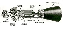
Nuclear drives get their energy from nuclear disintegration, fission, fusion or annihilation . They are the most powerful drives in terms of thrust and outflow speed, but they are politically controversial.
Radioisotope forcing
Use: Drive (E)
In the case of radioisotope propulsion , a gas with a low molar mass flows through a radioisotope, for example 238 Pu or 90 Sr. Due to natural decay, this heats up and thus also the gas. The gas is then expanded through a Laval nozzle . There was work on this, for example, in the Poodle project from 1961 to 1965 in the USA.
- : 800 s
- Thrust: 1-10 N
Solid-core reactor
Use: Drive (E)
In the case of nuclear rocket propulsion systems , the nuclear fission propulsion system should be mentioned, in which high temperatures are generated through nuclear reactions, which are then used to eject a supporting mass. By means of nuclear fission , hydrogen or ammonia is extremely heated and then ejected under pressure. These include the ongoing 1954 to 1972 Project NERVA of NASA , and in 1992 Timber Wind under the SDI initiative. In the past, the Soviet Union also worked with the RD-0410 engine on fission engines with a solid core for space travel.
- : 1000 s
- Thrust: 100-1000 kN
Gas nuclear reactor
Use: Drive (T)
As mentioned above, the temperature in the reactor must be increased in order to increase the drive power. Since the fissile material sets a natural temperature limit for solid core reactors due to its melting temperature, there are considerations to develop reactors with a gaseous core, so-called gas core reactors . This made it possible to achieve discharge velocities for impulses of up to 5000 s. The disadvantage, however, is that the core is exposed and therefore there is always a loss of fuel through the outlet nozzle. In order to prevent this, closed gas nuclear reactors were also considered, where the hot reactive plasma is filled in quartz tubes. There is no loss of fuel here, but the momentum is reduced to 2000 s.
- : 5,000 s
- Thrust: 100-1000 kN
Driven by fission products
Use: Drive (T)
Since part of the fuel always leaves the nozzle in a gas nuclear reactor with an open core, it is possible to further increase the outflow speed of the drive by only ejecting the fission products themselves (fission fragment rocking). The radioactive particles are made to react with the help of magnetic fields and kept away from the walls. The fission products are then expelled.
- : 100,000 s
- Thrust: unknown
Nuclear pulse drive
Use: Drive (E)
The concept was proposed in the 1950s and 1960s. The Orion and Daedalus projects, for example, have provided spaceships that trigger a nuclear explosion at the stern every few seconds. The spaceship would then have been pushed forward by the explosive effect. The advantage of such a drive is the simplicity of the concept, which can already be implemented with today's technologies, although the final questions regarding radiation protection for the crew and the spaceship itself have not been finally clarified.
Research in progress at the beginning of the 1960s was discontinued for political and legal reasons, in particular because of the treaty banning nuclear weapons tests in the atmosphere, in space and under water . Because of the necessary treaty changes, they could only be resumed in the international community.
- : 3,000-10,000 s
- Thrust: 100-10,000 kN
Fusion drive
Use: Drive (T)
This drive is similar to the nuclear fission drive, except that the energy is obtained from nuclear fusion and is therefore much higher. The energy of nuclear fusion is passed on to a low molecular weight gas, e.g. hydrogen, by means of neutron collisions. The “ash” of the fusion is also mixed into the exhaust gas jet, the resulting hot plasma is relaxed by means of a magnetic nozzle.
The buzzard ramjet proposed by the physicist Robert W. Bussard works similarly to a ramjet . A buzzard collector uses a magnetic force field to collect interstellar gas (mainly hydrogen) and feed it to a Polywell nuclear fusion reactor . The fusion products are then expelled. The great advantage of this concept is that the spaceship only has to carry a certain amount of fuel with it, namely enough to reach the minimum collection speed. However, this requires a proton-proton reaction .
- : 47,000 s
- Thrust: 30 kN
Photon rocket
Use: Drive (T)
With a photon rocket, u. a. suggested by Eugen Sänger , a nuclear reactor would heat a black surface so much that the black body radiation generated by the surface would generate thrust. The disadvantage is that very large amounts of energy are required to generate the tiniest thrust forces. Since the rocket loses mass through nuclear fission / fusion / annihilation, the specific impulses are low. The radiator (the black area) would be made of tungsten or graphite. Photon missiles are technologically feasible, but ineffective. A LiIon battery could finally be accelerated to a few cm / h. Solar cells would be pointless here, as they act more strongly than solar sails.
- : depending on the reactor
- Thrust: ≈ 3 N / GW
Fission sails
Use: Drive (T)
The fission sail was proposed by Robert L. Forward . A radiation-absorbing surface that is as large and as light as possible is coated on one side with radioisotopes, preferably alpha emitters. The natural decay of the radioisotopes releases helium nuclei ( alpha radiation ), which can only fly away in one direction. The principle is similar to a sun sail , but also works without sunlight. For example, the sail can be coated with 240 cm , which is a waste product in nuclear fission reactors, so that the following reaction takes place:
where the end product 220 Rn is gaseous and escapes. The following performance data can be achieved with this:
- : ≈40,000 s
- Thrust: ≈ 10 N / km²
Saltwater nuclear missile
Use: Drive (T)
The saltwater nuclear missile was proposed by Robert Zubrin . A little (20%) uranium or plutonium salt is added to the water. So that the critical mass is not reached, the salt water is divided into various small containers that are lined with neutron absorbers. The salt water is pumped from various containers into a reaction chamber. There the critical mass of the uranium or plutonium salt is finally reached and the nuclear chain reaction begins. The water in which the salts are dissolved acts as a moderator and support mass at the same time. The chain reaction generates an enormous amount of heat, which causes the water to evaporate; the mixture of water vapor and fissile material leaves the drive through a Laval nozzle . The advantages of the drive concept are the low consumption of fissile material compared to pure propulsion with fission products and the high thrust and specific impulse. The disadvantage is the enormous amount of heat generated by the nuclear chain reaction, so that the maximum neutron flux may only take place outside the reaction chamber.
- : 10,000 s
- Thrust: 10 MN
Antimatter Propulsion
Use: Drive (T)
The energy for this propulsion would be provided by a pair annihilation of matter and antimatter . During this process, the entire rest energy of the particles is completely released. A little antimatter is shot into a cloud of matter. The matter heats up enormously as a result, nuclear fusion processes set in and continue to heat the matter. This is then ejected through a magnetic nozzle.
The greatest problem from today's point of view is the generation and storage of antimatter. Since the production consumes as much energy as the reaction later supplies, production on board the spaceship is ruled out. The antimatter would have to be carried. With the current state of the art, an antimatter drive is not possible, since there is no way of generating large amounts of antimatter. Only 0.1 grams of antiprotons would be needed for a flight to Mars and back, but even the production of this small amount of antiprotons is currently utopian .
- : ≈ 400,000 s
- Thrust: 100 kN
Propulsion without fuel
In the following, propulsion methods are presented in which the spacecraft itself does not consume any fuel. Since it experiences a change in speed (delta v) due to the methods mentioned below, the specific momentum is always infinite according to the basic rocket equation .
Awning
Use: position control, drive (F)
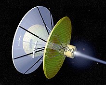
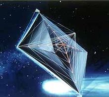
So-called solar sails are under development and are intended to make use of the effect of radiation pressure by capturing electromagnetic radiation with a large sail and being propelled by it. The thrust would be minimal (and would decrease quadratically with the distance from the radiation source), but it would have arisen without fuel consumption and would remain constant as long as the influence of radiation sources is used with the sail. With a laser sail, a laser beam is aimed at the sail.
- : infinite
- Thrust: 9 N / km² @ 1 AU
Tether
Use: path control (F)
Tethers are long ropes that are laid out in space at right angles to the magnetic field of a planet. When an electrical conductor moves through a magnetic field, voltage is induced in it. Thus, a satellite that spreads long tethers can use it to supply itself with energy. The usefulness of this effect is limited by the fact that the conductor in which the voltage is induced itself generates a field opposite to the earth's magnetic field. This slows down the entire spacecraft and tether system (Lenz's rule). Accordingly, a tether through which a strong current flows can also contribute to the acceleration of a satellite, since a force acts on a current-carrying conductor in the magnetic field (Lorentz force). Studies show that such electric tethers can be effective in accelerating or decelerating the satellite despite only slow orbit changes due to the fuel savings. With Tethers it is also possible to “rappel down” satellites.
- : infinite
- Thrust (electric): unknown mN
- Thrust (manual): unknown kN
Carrier ships
Usage: Start (E)
To reduce the fuel masses required for take-off, there are concepts to use carrier aircraft, for example space planes , to transport the spacecraft to a certain height. Elevation balloons are also conceivable . See also the lower level of Sänger (space transport system) .
- : infinite (based on the spaceship)
- Thrust: unknown MN
Space cannon

Use: (unmanned) take-off / transport (E)
Ballistic methods are also being discussed and researched as a means of transport into orbit . The idea is originally based on Jules Verne's vision of the space cannon in From Earth to the Moon . The "projectile" must be largely resistant to acceleration (satellites if necessary). Advantages over rocket technology would be significantly reduced costs through a higher payload share and also a lower risk of accidents, including a. as little or no highly explosive rocket fuel would be carried. One of the first projects was Gerald Bull's HARP project , which achieved a maximum speed of 3 km / s and an altitude of 180 km with optimized artillery technology, i.e. a suborbital flight ( Kármán line ). A follow-up project of the 1990s, SHARP , worked with light gas cannon technology and aimed for maximum speeds of 7 km / s. After the end of the financed SHARP research project, the project team founded the company Quicklaunch, which tries to further develop and commercialize this technology. The railgun technology is considered.
- : infinite
- Thrust: 2.0-32.4 MN
Space elevator
Usage: Start (E)
Another suggestion is that of a space elevator, a kind of elevator which, starting at the ground, should lead out of the earth's atmosphere into space. After the year 1895 (in today's opinion technically impossible) erecting a pylon (Engl. Space fountain was) proposed to outer space, the 1957 (Engl. The space elevator has space elevator ) modified idea in recent years considered scientifically numerous. In today's versions, the concept includes a solid rope that would be anchored to the earth's surface and at the other end of which a weight would hang just above the geostationary orbit , whereby the centripetal force should pull the rope taut and enable an elevator to move up and down on it. A central problem is the strength of the rope - however, the strength values have been significantly improved recently. For example, graphene or carbon nanotubes achieve the necessary strength values.
- : infinite
- Thrust: unknown
Electromagnetic catapult
Usage: Start (E)
There is a scientific proposal for an electromagnetic catapult ( mass driver ). Such an electromagnetic catapult can work on the principle of a coilgun or railgun on a larger scale: The object to be shot is attached to a launch device, for example a rail shape, and accelerated on it until it comes to free flight at the end of the device. Alternatively, a maglev system can also be used, as is the case with mass drivers . An electromagnetic catapult on the lunar surface, for example, can generate more than half the energy needed for satellites and spacecraft to launch them into lunar orbit. The ESA tested a system with a rocket sled to help launch Hopper .
- : infinite
- Thrust: 100-10,000 kN
Magnetic sail
Use: Drive (E)
Magnetic sails generate magnetic fields to deflect the charged particles of the solar wind to propel a spacecraft. This can be both a static magnetic field, which can be generated, for example, by a superconductor permanently installed on the spacecraft, and movable arrangements of one or more magnets using the Magnus effect according to the principle of the Flettner rotor . Dynamic configurations switched by power electronics are also conceivable. With a magnetic sail it is also possible to be attracted or repelled by the magnetosphere of a planet. It is also possible to introduce currents into the captured plasma in order to deform and strengthen the magnetic field. This approach is called M2P2 (Mini-Magnetospheric Plasma Propulsion). Another approach is to shoot a plasma beam at the spacecraft. This approach is similar to the Laser Matter Sail and is called MagBeam .
Matter sail
Use: Drive (T)
A matter radiator, e.g. B. a particle linear accelerator, rests on a large mass (moon, asteroid). From here, a well-bundled particle beam is aimed at the sail of matter in the spaceship, thereby accelerating it. Since the speed of the particle beam can be adapted to the speed of the spaceship (maximum impulse transmission), the energy efficiency is significantly higher than with the laser sail. In addition, part of the material flow can be captured by the spaceship. The spaceship can take off with empty “fuel tanks” and fills them while accelerating. Once at its destination, it could brake with this collected fuel.
- : infinite
- Thrust: 1-1000 mN
Microwave drive
See also
literature
- Marc G. Millis (et al.): Frontiers of Propulsion Science. American Inst. Of Aeronautics & Astronautics, Reston 2009, ISBN 1-56347-956-7 , abstract (pdf; 1.2 MB)
- Martin Tajmar : Advanced space propulsion systems. Springer, Vienna 2003, ISBN 3-211-83862-7
- Paul A. Czysz: Future spacecraft propulsion systems. Springer, Berlin 2006, ISBN 3-540-23161-7
- Claudio Bruno, Antonio G. Accettura: Advanced Propulsion Systems and Technologies, Today to 2020. American Inst. Of Aeronautics & Astronautics, Reston 2007, ISBN 978-1-56347-929-8
- Eugen Sänger : Space travel - technical overhaul of the war ; Article in Foreign Policy - Journal for International Issues , 1958, Issue 4
- Michael Marshall: Engage the x drive - Ten ways to traverse deep space. NewScientist, December 21, 2009
- Kelvin F. Long: Deep space propulsion. Springer, New York 2012, ISBN 978-1-4614-0606-8 .
- E. Messerschmid, S. Fasoulas: Space Systems , Springer Vieweg, 5th edition from 2017, ISBN 978-3-662-49637-4
- Chapter 5: Thermal Missiles , pp. 181-240
- Chapter 6: Electric Drives , pp. 241–260
Web links
- Greg Goebel: Spaceflight Propulsion (public domain) Comprehensive presentation of propulsion mechanisms for space travel
- ESA Advanced Concepts Team Homepage
- NASA Institute for Advanced Concepts
- American Institute of Aeronautics and Astronautics Presentation on Advanced Propulsion Concepts, May 2008, (PDF; 4.4 MB)
- M. Tajmar: Advanced Space Propulsion Systems. (PDF; 5.1 MB) Vienna University of Technology, archived from the original on February 27, 2007 ; accessed on December 17, 2008 (English).
- Space, Propulsion and Energy Sciences International Forum 2009, AIP Conference Proceedings abstracts
- Millis, Marc G .; Maclay, (et al.): Study of Vacuum Energy Physics for Breakthrough Propulsion. 2004, NASA Technical Reports Server, accessed September 4, 2012
- Advanced Propulsion Study Air Force Research Laboratory, 2004 (pdf, accessed May 30, 2009; 4.86 MB)
- Anf: Revolutionary rocket propulsion: Thrust without fuel , in Spiegel Online, Date: August 6, 2014, Accessed: August 14, 2014
swell
- ^ Dan M. Goebel et al .: Fundamentals of electric propulsion - Ion and Hall thrusters. Wiley, Hoboken 2008, ISBN 978-0-470-42927-3 , p. 3.
- ^ Arianespace reveals manifest, notes launch market variety. In: Spacenews. September 9, 2019, accessed September 9, 2019 .
- ↑ Radiofrequency Ion Thruster, Model RIT-10. ( Memento from March 10, 2008 in the web archive archive.today )
- ^ John E. Foster et al .: The High Power Electric Propulsion (HiPEP) Ion Thruster. (PDF; 603 kB) NASA, September 2004, p. 8 , accessed on September 7, 2012 (English).
- ^ Electric Spacecraft Propulsion - Hall Effect Thrusters sci.esa.int
- ^ Dan M. Goebel, et al .: Fundamentals of Electric Propulsion: Ion and Hall Thrusters. pdf, jpl.nasa.gov, accessed February 1, 2013
- ↑ The PIT MkV Pulsed Inductive Thruster (PDF; 2.6 MB)
- ↑ bibcode : 2008AIPC..969..518F
- ↑ Helicon Double Layer Thruster
- ↑ Craig H. Williams et al: Realizing "2001: A Space Odyssey": Piloted Spherical Torus Nuclear Fusion Propulsion. (PDF; 3.0 MB) NASA, March 2005, accessed on September 7, 2012 (English, rounded values).
- ↑ Singer, Eugen (1956). On the mechanics of the photon jet propulsion. Munich: R. Oldenbourg. pp. 92.
- ↑ Singer, Eugen (1957). On the radiation physics of photon jet propulsion and weapon beams. Munich: R. Oldenbourg. pp. 173.
- ↑ ANTIPROTON-CATALYZED MICROFISSION / FUSION PROPULSION SYSTEMS FOR EXPLORATION OF THE OUTER SOLAR SYSTEM AND BEYOND (PDF; 753 kB) ( Memento from November 17, 2003 in the Internet Archive )
- ↑ a b Scott R. Gourley: The Jules Verne Gun ( Memento of 29 October 2011 at the Internet Archive ), in: Popular Mechanics , Dec. 1996, pp 54-57 (English).
- ↑ The HARP Project and the Martlet (English) on nasa.gov
- ^ Charlene Crabb: Shooting at the moon . In: newscientist.com (Ed.): New Scientist . No. 1937 , August 6, 1994 (English, newscientist.com [accessed December 29, 2011]).
- ↑ David Shiga: Blasted into space from a giant air gun. newscientist.com, October 7, 2009, accessed December 21, 2011 .
- ↑ Quicklaunch ( Memento of September 27, 2012 in the Internet Archive ) Website (archived, English)
- ↑ NASA's next-gen space launch system Could Launch Scramjets from a Massive Railgun popsci.com; Railguns for space launch ( Memento of the original from January 29, 2012 in the Internet Archive ) Info: The archive link was inserted automatically and has not yet been checked. Please check the original and archive link according to the instructions and then remove this notice. nextbigfuture.com
- ^ Ian R. McNab: Launch to Space With an Electromagnetic Railgun IEEE TRANSACTIONS ON MAGNETICS, VOL. 39, NO. 1, JANUARY 2003, p. 295ff, pdf accessed on January 29, 2012
- ↑ Calculated: 2.0 MN for quick launch target 6 km / s for 45 kg projectiles over a length of 400 m How a giant underwater cannon could fire us into space
- ↑ Calculated: 32.4 MN for HARPs achieved 3.6 km / s for 180 kg projectile over a length of 36 m
- ↑ Changgu Lee, Xiaoding Wei, Jeffrey W. Kysar, James Hone: Measurement of the Elastic Properties and Intrinsic Strength of Monolayer Graphene . In: Science . tape 321 , no. 5887 , 2008, p. 385-388 , doi : 10.1126 / science.1157996 .
- ↑ C. Cattell, P. Catto, H. Funsten, D. Garnier, N. Hershkowitz, R. Myers, H. Petschek, D. Winske: Physics and Technology of the Feasibility of Plasma Sails ( Memento of February 27, 2009 in Internet Archive ). Journal of Geophysical Research, 2005.


