
Magnetic resonance imaging


The magnetic resonance imaging , hereinafter MRI or MR (as Tomography of ancient Greek τομή tome , German , cut ' and γράφειν graphein , German , write' ), is an imaging technique which especially in medical diagnosis for illustrating the structure and function of tissues and Organs in the body being used. It is based physically on the principles of nuclear magnetic resonance ( english Nuclear Magnetic Resonance, NMR ), particularly the field gradient NMR , and is therefore also known as magnetic resonance imaging called ( colloquially occasionally magnetic resonance shortened). The abbreviation MRI , which can also be found, comes from the English name Magnetic Resonance Imaging .
MRT can be used to generate sectional images of the human (or animal) body, which allow an assessment of the organs and many pathological organ changes. It is based on - in a magnetic resonance tomography system (short form: nuclear spin tomograph, MRT device) - generated very strong magnetic fields as well as alternating magnetic fields in the radio frequency range with which certain atomic nuclei (usually the hydrogen nuclei / protons ) in the body are resonantly excited, creating an electrical circuit in a receiver circuit Signal is induced . Since the object to be observed "radiates itself", MRT is not subject to the physical law of the resolution of optical instruments, according to which the wavelength of the radiation used must be smaller, the higher the required resolution. In MRT, object points in the sub-millimeter range can be resolved with wavelengths in the meter range (low-energy radio waves). The proton density and different relaxation times of different types of tissue are an essential basis for the image contrast . In addition, the different content of hydrogen atoms in different tissues (e.g. muscles, bones) also contributes to the image contrast.
No harmful X-rays or other ionizing radiation are generated or used in the device . However, the effects of alternating magnetic fields on living tissue have not been fully researched.
Procedures and Systems
Numerous special MRI procedures have been developed in order to be able to display information about their microstructure and function (especially their blood flow ) in addition to the position and shape of the organs , for example:
- the Real-time MRI for cinematic display of moving joints or organs (eg. as heart)
- The magnetic resonance angiography (MRA) for the representation of the vessels,
- the functional magnetic resonance imaging (fMRI or fMRI) of the brain,
- the perfusion MRI to examine the tissue blood flow,
- the diffusion - or diffusion tensor imaging (DTI) for a virtual reconstruction of the nerve fiber connections,
- MR elastography .
Depending on the design, a distinction is made between closed MRT systems with a short or long tunnel and open MRT systems (oMRI) with a C-arm or a tunnel that is open to the side. Closed tunnel systems deliver comparatively better image data, while open MRT systems enable access to the patient under MRI control.
Another distinguishing criterion is the type of magnetic field generation. Permanent magnets or conventional electromagnets are used for weak magnetic fields of up to approx. 0.5 Tesla flux density (magnetic induction), while superconducting magnetic coils are used for higher fields .
Historical development
The specific magnetic resonance of atomic nuclei with a magnetic dipole moment described by Felix Bloch as well as Edward M. Purcell in 1945/46 was the basis for the magnetic resonance spectroscopy method, which has also been used in medicine since the 1950s . Magnetic resonance tomography was invented as an imaging method by Paul C. Lauterbur in September 1971; he published the theory of imaging in March 1973. The main parameters that contribute to image contrast (differences in the relaxation times of tissues) had been described by Erik Odeblad a good 20 years earlier .
Paul Lauterbur (USA) had two fundamental ideas that made imaging based on nuclear magnetic resonance (NMR) possible in the first place. First, he did it with field gradient NMR ; H. with the introduction of magnetic gradient fields in the conventional NMR experiment, to assign the NMR signals to specific spatial areas of an extended sample (spatial coding). Second, he suggested a method in which different by rotating the ortskodierenden magnetic field in successive experiments spatial codings (projections) has been made of the examination subject from which then use the filtered back projection ( english filtered back projection ) an image of the object under examination could be calculated. His result, published in 1973, shows a two-dimensional image of two small tubes filled with normal water in an environment of heavy water .
For a practical use of this discovery, special innovations in apparatus were necessary. The Bruker company in Karlsruhe, Germany, one of the manufacturers of NMR spectrometers, developed “quartz-controlled” NMR pulse spectrometers in a group led by physicists Bertold Knüttel and Manfred Holz in the early 1960s . B. could be used by Peter Mansfield for basic experiments. From 1974 onwards, Mansfield developed mathematical methods to quickly convert the signals into image information, as well as techniques for slice-selective excitation. Furthermore, in 1977 he introduced the use of extremely fast switching of the gradients (EPI = Echo Planar Imaging ). This made it possible to obtain images in well under a second (“snapshot technology”), which, however, has to be bought with compromises in image quality to this day. Mansfield is also thanks to the introduction of magnetically shielded gradient coils. In his last active years he was looking for solutions to reduce the considerable noise pollution for the patients through the extremely fast gradient switching.
Other important contributions to the broad clinical use of magnetic resonance imaging (MRT) come from German research laboratories. In Freiburg, Jürgen Hennig and colleagues developed a variant of the Spin-Echo MRT at the beginning of the 1980s , which is known today under the abbreviations RARE ( Rapid Acquisition with Relaxation Enhancement ), FSE ( Fast Spin Echo ) or TSE ( Turbo Spin Echo ). It is widely used because of its sensitivity with regard to pathological tissue structures and its measurement efficiency. In 1985, Axel Haase , Jens Frahm and Dieter Matthaei in Göttingen achieved a fundamental breakthrough in MRI with the invention of the FLASH rapid image method . The FLASH technology reduced the measurement times at that time by up to two orders of magnitude (factor 100) without any substantial loss of image quality. The method also enables uninterrupted, sequential measurements in dynamic equilibrium as well as completely new clinical examinations such as recordings of the abdominal cavity while breathing is held, dynamic recordings of cardiac films synchronized with the ECG, three-dimensional recordings of complex anatomical structures, vascular representations with MR angiography and today too functional mapping of the cortex with particularly high resolution. From the mid-1980s, this paved the way for a broad, primarily clinical, application of MRI in medical diagnostics.
The contribution by Raymond Damadian (USA) is controversial , who in 1977 presented the first “magnetic resonance image” of a person and in 1974 applied for a US patent for the use of NMR for cancer diagnosis. Although the patent did not describe a method for imaging, but only a point measurement, Damadian won over $ 100 million from various MRI manufacturers with another patent (multi-slice, multi-angle measurements, e.g. for MRI examinations of the spine) . His original NMR scanner, which did not produce images, was never used clinically, and the cancer detection method that it allegedly found with it is not without doubt. It is based on differences in the NMR relaxation times of healthy tissue and tumor tissue. This observation published by Damadian in 1971 (using magnetic resonance spectroscopy) was confirmed in principle, but later had to be put into perspective to the effect that the differences did not apply consistently. Different relaxation times of the tissue are neither necessary nor sufficient for the presence of tumor tissue in the test subject. Damadian was not involved in the award of the Nobel Prize for imaging NMR (MRT, English MRI ), against which he publicly protested violently.
physics
short version
This section describes the principle of MRI in a very simplified and not complete manner. For a more precise description, see the next sections.

The method is based on the fact that the atomic nuclei in the examined tissue are stimulated in a phase-synchronized manner to a specific movement by a combination of static and high-frequency magnetic fields and then emit a measurable signal in the form of an alternating voltage until the movement has subsided. This movement is called Larmor precession and can be observed mechanically analogously on a toy top when its axis of rotation is not vertical , but precession around the vertical (see illustration on the right). Both for the excitation and for the observation of the signal, a resonance condition must be met, with the help of which it is possible to determine the location of the precessing nuclei using inhomogeneous static magnetic fields.
Some atomic nuclei (such as hydrogen nuclei ) in the molecules of the tissue to be examined have their own angular momentum ( nuclear spin ) and are therefore magnetic. After applying a strong static magnetic field, these nuclei generate a small longitudinal magnetization in the direction of the static field ( paramagnetism ). By applying an additional high-frequency alternating field for a short time in the radio frequency range , this magnetization can be deflected (tilted) out of the direction of the static field, i.e. partially or completely (saturation) converted into a transverse magnetization. The transverse magnetization immediately begins to precess around the field direction of the static magnetic field , i.e. H. the direction of magnetization rotates (see figure for precession). This precession movement of the tissue magnetization induces an electrical voltage like the rotation of the magnet in the dynamo in a coil (receiver circuit) and can thus be detected. Their amplitude is proportional to the transverse magnetization.
After switching off the high-frequency alternating field, the transverse magnetization (again) decreases, so the spins align themselves again parallel to the static magnetic field. For this so-called relaxation they need a characteristic decay time. This depends on the chemical compound and the molecular environment in which the precessing hydrogen nucleus is located. Therefore, the different types of tissue differ characteristically in their signal, which leads to different signal strengths (brightnesses) in the resulting image.
Basics

The physical basis of magnetic resonance imaging (MRI) is the nuclear magnetic resonance (engl. Nuclear magnetic resonance , NMR ). Here one uses the fact that the atomic nuclei of hydrogen ( protons ) have their own angular momentum ( spin ) and, associated with this, have a magnetic dipole moment . Some other atomic nuclei also have spin and thus receive a magnetic moment . (From the point of view of classical physics, an atomic nucleus can be viewed in simplified form as a spherical top with an angular momentum and a magnetic dipole moment, although the cause of its angular momentum cannot be described correctly in the classical way.)
If such a core is brought into a static magnetic field , its energy is lowest when the magnetic dipole moment is aligned parallel to the field . A torque acts on all other atomic nuclei, which tries to turn the direction of the magnetic moment in the direction of the magnetic field. Because of the intrinsic angular momentum of the atomic nucleus and the conservation of angular momentum , this results in the precession motion , i.e. H. the angular momentum orientation of the core rotates around the direction of the applied magnetic field without changing the angle of attack.

Due to the thermal energy of the nuclei at normal temperatures, the dipole moments are almost completely random ( isotropic ); there is only a very small excess of atomic nuclei (according to the Boltzmann distribution ), whose dipole moments are aligned in the direction of the static magnetic field. Only this small excess causes the externally measurable magnetization in the direction of the external static field (the longitudinal magnetization in the longitudinal direction ).

The precession movement of the nuclear spins takes place with the Larmor frequency . It depends on the strength of the external magnetic field and on the nucleus under consideration; for protons at 1 Tesla it is 42.58 MHz, i.e. in the VHF radio wave range. An additional high-frequency field that oscillates perpendicular to the static magnetic field , i.e. in the transverse plane, and whose frequency is in resonance with the Larmor frequency , deflects all nuclei phase-synchronously from their current position to the static field. The macroscopic magnetization is tilted from the direction of the static field, resulting in a transverse magnetization which, if the alternating field is exposed to the correct duration, can be at most exactly the same as the original longitudinal magnetization (saturation).

An alternating voltage is induced in a measuring coil by the rotating transverse magnetization. Its frequency is the Larmor frequency, which in a static gradient field depends on the location; its amplitude indicates the strength of the transverse magnetization, which in turn depends on the exact sequence (sequence) of pulses, the location and the type of tissue.
The aim of MR tomography is the generation of slice images (of any orientation) of the spatial distribution of the transverse magnetization .

Spin-lattice relaxation (longitudinal relaxation T1)
If the magnetization has been tilted out of the longitudinal direction (z-direction) by an alternating magnetic field of the correct frequency, strength and duration so that it precesses in the xy-plane , the longitudinal magnetization initially has the value zero. If the alternating field is then switched off, the state of equilibrium begins to rebuild itself with exclusively longitudinal magnetization, i.e. lower energy. The cause of this spin-lattice relaxation is the influence of fluctuating interference fields on the moments of the individual nuclei, which are caused by neighboring atoms, which in turn are in thermal equilibrium with the wider environment, which for historical reasons is called "lattice". That means, the magnetization aligns itself again along the static field , the energy goes from the nuclei via the atoms into the lattice. This alignment is exponential:

- ,

where the strength of the magnetization in the direction of is in the equilibrium state. The constant indicates the state in which the system is out of equilibrium at the beginning of the relaxation process (e.g .: saturation ,: inversion). The time until the z-component has reached approx. 63% of its initial value again is called the spin-lattice relaxation time or time.


The times in pure, low-viscosity liquids such as B. water are usually in the range of a few seconds. Liquids with a higher viscosity (e.g. oils) or water in structured systems such as B. gels, porous materials or tissues generally have shorter times. In highly ordered solids, on the other hand, very long relaxation times are found, which can possibly be in the range of hours. However, because of the short times in solids, such materials do not play a role in conventional magnetic resonance tomography. Typical values for in human tissue are between a few seconds for body fluids such as blood or cerebrospinal fluid (liquor) and approx. 100 ms for body fat (for example the time of liquor at 1.5 Tesla is around 4 seconds, the time of the gray matter in the brain is around 1.2 seconds).

Spin-spin relaxation (transverse relaxation time T2)
The transverse magnetization of a spin ensemble now decays, similar to how the component increases, through interaction with neighboring atoms. Here, however, it is the so-called spin-spin interaction that is responsible for the dephasing. The decay can again be represented by an exponential function, but with a different time constant :

- .

The transverse magnetization in the xy plane often decreases much faster than can be explained by the spin-spin interaction. The reason for this is that an MR image is averaged over a volume element in which the external magnetic field is not constant (but rather inhomogeneous). After the HF signal has been removed, the phases of the precession movement of the nuclei shift from one another, and the xy components of the individual nuclear spins diverge.
Measurement sequence, location coding, image structure

For a better understanding, the principle of the basic spin echo sequence ( invented by Erwin Hahn in 1950 ) is briefly outlined here. In this context, a “sequence” (also known as “pulse sequence”) is a sequence of high-frequency and magnetic gradient fields that are switched on and off many times a second in a specified order.
At the beginning there is a high -frequency pulse of the appropriate frequency ( Larmor frequency ), the so-called 90 ° excitation pulse . This deflects the magnetization by 90 ° across the external magnetic field. It begins to revolve around the original axis. As with a top that is pushed, this movement is called precession .
The resulting high-frequency signal can be measured outside the body. It decreases exponentially because the proton spins get out of sync (“dephase”) and are increasingly destructively superimposed. The time after which 63% of the signal has decayed is called the relaxation time ( spin-spin relaxation ). This time depends on the chemical environment of the hydrogen; it is different for each type of tissue. Tumor tissue has z. B. usually a longer time than normal muscle tissue. A weighted measurement therefore shows the tumor lighter than its surroundings.
A suitable 180 ° rephasing high-frequency pulse can have the effect that part of the dephasing ( dephasing due to temporally unchangeable magnetic field inhomogeneities) is reversed at the time of the measurement, so that more spins are again in the same phase. The signal strength then does not depend on the relaxation time, but only on the relaxation time, which is based on non-reversible effects. Depending on the sequence parameters, the signal can also depend on the so-called relaxation time ( spin-lattice relaxation ), which is a measure of the speed at which the original longitudinal alignment of the spins with the external magnetic field is restored. The time is also tissue-specific, but usually significantly (5 × to 20 ×) longer than the time. The time of water is z. B. 2.5 seconds. -weighted measurement sequences allow a better spatial resolution because of the stronger signal, but a lower tissue contrast than -weighted images.

In order to obtain a -weighted image, the rephasing pulse is set relatively late so that the spin-spin relaxation has time to take effect; one speaks of a long echo time TE. The time interval until the next measurement is very long so that the spin-lattice relaxation can also take place completely in all tissues and the subsequent measurement can be fully stimulated again everywhere. One speaks of a long repetition time TR. With a long TE and a long TR, you only get a bright signal from tissues with a long time. Conversely, for a -weighting one needs short TE and short TR, then the different spin-lattice relaxations of different tissues predominate in the image contrast. A sequence with a short TE and a long TR creates a contrast that depends only on the concentration of protons in the tissue, which practically corresponds to the number of hydrogen atoms. These so-called proton density (PD) -weighted images have a weak contrast but a high spatial resolution. There are numerous further developments of these simple spin echo sequences, for example for acceleration or with the suppression of the adipose tissue signal. A clinical MRT examination comprises differently weighted image series and several spatial levels.
In order to be able to assign the signals to the individual volume elements ( voxels ), a spatial coding is generated with linear, location-dependent magnetic fields ( gradient fields ). This makes use of the fact that the Larmor frequency for a certain particle depends on the magnetic flux density (the stronger the field component perpendicular to the direction of the particle angular momentum, the higher the Larmor frequency):
- A gradient is on at the excitation and ensures that only a single layer of the body has the appropriate Larmor frequency, are thus deflected only the spins of the layer ( slice selection ).
- A second gradient across the first is briefly switched on after the excitation and causes a controlled dephasing of the spins in such a way that the spins dephase at different speeds in each image line, which weakens the sum signal ( phase coding gradient ). This measurement is repeated with incrementally changed gradient strength as often as image lines are to be calculated. The signal weakening due to dephasing changes depending on the position of the transmitting spins along the gradient.
- The third gradient is switched at right angles to the other two during the measurement; it ensures that the spins of each image column have a different precession speed, i.e. send a different Larmor frequency ( readout gradient, frequency coding gradient ).
The measurements are entered line by line in a matrix ("k-space"). The k-space thus contains the sum signal of the horizontal spatial frequencies in the horizontal and the sum of the vertical spatial frequencies in the vertical. With a two-dimensional Fourier transformation , the contributions of the individual frequencies are separated, i. H. the signal strength is determined for each voxel. All three gradients together result in a coding of the signal in three spatial planes. The received signal belongs to a specific layer of the body and contains a combination of frequency and phase coding, which the computer can convert into a two-dimensional image using an inverse Fourier transform.
Magnetic flux densities used
The magnetic flux density has a direct effect on the signal quality of the measured data, since the signal-to-noise ratio is roughly proportional to the flux density . That is why there has been a trend towards ever higher flux densities since the beginnings of MRI, which requires the use of deep-frozen superconducting coils. As a result, the costs and the technical effort increase significantly with higher flux densities. Inhomogeneous field configurations arise particularly in the case of superconducting coils with large openings for examining people.
Low field devices with 0.1–1.0 T (Tesla) are operated today with permanent magnets as laboratory devices for technical or small animal examinations . In the case of cryo-electromagnets in human medicine, the flux density for diagnostic purposes is usually 1.5 T to 3.0 T. If 3 T is exceeded, the patient or test person may only be driven very slowly into the area of the superconducting coil because it Otherwise , the eddy currents in the brain can lead to lightning, dizziness and nausea.
Even higher flux densities ( ultra-high field systems ) are currently only used in human medicine for research purposes, but not yet for routine examinations. The following institutions operate MRT systems for examinations on humans with flux densities of 7 T or more in German-speaking countries:
- the Leibniz Institute for Neurobiology (IfN) in Magdeburg (7 Tesla device for head examinations, since 2005; 9.4 Tesla system for examinations on small animals, since 2018)
- the Erwin L. Hahn Institute for Magnetic Resonance at the Universities of Duisburg-Essen and Radboud (Nijmegen) (7 Tesla whole-body MRI, since 2006)
- the Institute for Biomedical Engineering (IBT) at ETH Zurich (7-Tesla whole-body MRI, since 2006)
- the Max Planck Institute for Biological Cybernetics in Tübingen (9.4 Tesla system for head examinations, since 2007; 14.1 Tesla system for examinations on small animals)
- the General Hospital of the City of Vienna as part of the Medical University of Vienna (7 Tesla whole-body MRI, since 2008)
- the Max Planck Institute for Cognitive and Brain Sciences in Leipzig (7 Tesla device for head examinations, since 2008)
- the German Cancer Research Center in Heidelberg (7 Tesla whole-body MRI, since 2008)
- the Max Delbrück Center for Molecular Medicine in Berlin (7 Tesla whole-body MRI, usable from 2009 on)
- the Research Center Jülich (9.4 Tesla MR PET -Hybridsystem for head examinations, from April 2009 to early 2014)
- the University Hospital Erlangen together with the Friedrich-Alexander-University Erlangen-Nürnberg and Siemens Healthcare (7-Tesla whole-body MRI, since 2015)
- the University Hospital Würzburg ( German Center for Heart Failure ) (7-Tesla whole-body MRI, since 2017)
- the University Hospital Bonn ( German Center for Neurodegenerative Diseases (DZNE) Bonn) (7 Tesla MRI for head examinations, since 2016)
A whole-body MRI with a flux density of 11.7 T is being developed at the CEA Neurospin Center in Saclay (France).
Superconducting magnets remain energized and magnetic in the event of a power failure, which means that in an emergency (building fire or similar) rescue workers can be at risk by pulling ferromagnetic equipment (breathing air bottles, ...) into the device opening. For this reason, the magnets are automatically quenched when a fire alarm is triggered by heating a point on the coil intended for this purpose, whereupon the magnet is discharged in a controlled manner via a bridging load resistor.
Experimental systems
In physical, chemical and biomedical research, high-field devices for samples and small animals with up to 21 T are common. With a diameter of a few centimeters, the opening of these devices is much smaller than that of the systems mentioned above. With such high-field tomograph z. B. Age determinations of objects are carried out that are chemically or radiologically impossible.
Image assessment
The signal strength of the voxels is mapped in coded gray values. Since it depends on numerous parameters (such as the magnetic field strength), there are no standard values for the signal of specific tissue and no defined unit, comparable to the Hounsfield units in computer tomography . The MR console only displays arbitrary (arbitrary) units that cannot be directly diagnosed. The image interpretation is based instead on the overall contrast , the respective weighting (synonymous weighting ) of the measurement sequence, and the signal differences between known and unknown tissues. Therefore, when describing a lesion, the findings do not speak of “light” or “dark”, but rather of hyperintense for high-signal , light and hypointense for low-signal , dark .
Depending on the weighting, the different tissues are shown in a characteristic intensity distribution:
- In the T1 weighting , fat tissue appears hyperintense (high-signal, light) and thus also fat-containing / -rich tissue (e.g. bone marrow ). This weighting is therefore well suited for the anatomical representation of organ structures and especially after administration of contrast medium ( gadolinium ) for better delimitation of unknown structures (e.g. tumor ).
- In the T2 weighting , stationary fluids appear hyperintense, so that fluid-filled structures (e.g. liquor spaces ) appear bright and signal-rich. This weighting is therefore suitable for displaying effusion and edema as well as z. B. to differentiate cysts from solid tumors. In X-ray images , especially in the special X-ray technology of computed tomography (CT), the terms hyperdense and hypodense are used to describe the relative degree of blackening.
- Proton-weighted images are dull but sharp. Cartilage can be assessed in great detail. In connection with a fat saturation pulse, PD images are therefore standard in joint examinations.
In voxel-based morphometry , MR images are processed algorithmically in order to determine objective parameters from them and analyze them statistically. These methods are used in particular to determine the size of certain brain structures when examining the human brain.
properties
Advantages of magnetic resonance imaging


One advantage of MRI over other imaging methods is the better soft tissue contrast. It results from the difference in fat and water content of different types of tissue. The process works without harmful ionizing radiation . A further improvement results from two series of exposures, with and without the administration of contrast media . B. by a more intense white coloring, inflammation foci or vital tumor tissue better recognized.
New, faster recording methods enable individual slice images to be scanned in fractions of a second, thus delivering real real-time MRI , which replaces previous experiments based on conventional fluoroscopy . In this way, for example, movements of organs can be displayed or the position of medical instruments can be monitored during an intervention ( interventional radiology ). Up to now , measurements synchronized with an EKG have been used to depict the beating heart (figure on the right) , whereby data from several cardiac cycles are combined to form complete images. Newer approaches for real-time MRT, on the other hand, promise direct cardiac imaging without EKG synchronization and with free breathing with a temporal resolution of up to 20 milliseconds.
The lack of radiation exposure is also essential, which is why this method is preferred over CT for examinations of infants and children and during pregnancy.
Disadvantages of MRI


- In standard clinical systems, the resolution is limited to about one millimeter due to technical factors, in particular the limited field strength. In the research area, spatial resolutions of less than 0.02 mm can be achieved.
- Metal on or in the body can cause side effects and image disturbances. Existing metallic foreign bodies (e.g. iron splinters in the eye or brain) can even become dangerous due to displacement or heating during the examination, so that a magnetic resonance examination may be contraindicated in such patients . Modern metal implants made of titanium and even steel alloys are para- or diamagnetic , depending on the composition, and therefore usually do not pose a problem in MRI.
- 1.5 Tesla MRIs are known to be safe for amalgam fillings . However, Turkish scientists show that newer MRIs with field strengths of 3 and more Tesla are not completely free of effects on the marginal leakage of amalgam fillings.
- Electrical devices can be damaged in the magnet. Carriers of an older pacemaker and similar devices were therefore not allowed to be examined so far. However, special devices offer the possibility of an examination up to usually 1.5 Tesla after they have been switched to a special MRT mode.
- Cochlear implants or similar magnetically supplied hearing implants can only be used with restrictions in terms of field strength and certain sequences. The manufacturers of these devices issue MRI approvals for their implants. In some cases, patients may be examined with up to 3 Tesla after surgical removal of the implant magnet. Possible complications include demagnetization and dislocation of the implant magnet, interactions with the implant circuitry, and artifacts in the MRI image. An MRI examination should only be carried out with a strict indication and should always be a case-by-case decision by the performing radiologist.
- Fast moving organs such as the heart can only be displayed with limited quality with most common devices or require movement compensation through multiple sampling over time. With multi-channel systems and RF receiver coils with numerous coil elements operated in parallel, these examinations are possible using methods such as parallel imaging and are increasingly finding their way into routine clinical diagnostics.
- The examination is often more time-consuming compared to other imaging procedures.
- The calcium content of bony structures cannot be quantified due to the field densities used under routine conditions, since bone tissue contains little water and little fat. Bone diseases such as On the other hand, due to the increased blood flow and the associated water content, inflammations or tumors, for example, are often easier to detect than with X-ray or computer tomography examinations.
- An allergic reaction to the contrast agent can occur very rarely , although MR contrast agents are generally much better tolerated than iodine-containing X-ray contrast agents. Recently, however, contrast medium- induced nephrogenic systemic fibroses have been observed occasionally .
- Due to the extremely fast switching of the magnetic fields, loud noises sometimes occur during the recording; Depending on the selected sequence, an intermittent chirping, knocking, humming, rattling or sawing can be heard; the repetition frequencies of the image generation can reach into the kHz range.
- The high power consumption for the direct cooling, the air conditioning and the ventilation system . This is 40-100 kilowatts in operation and around 10 kW in standby or standby mode , as some components, such as B. the vacuum pump, the cooling of the superconducting coil and parts of the control electronics must not be switched off even when the system is not in use in order to maintain superconductivity.
- The small diameter of the tube into which the patient is driven can lead to feelings of oppression and anxiety. In the meantime, however, there are also devices with a slightly larger tunnel opening of 75 cm (instead of 60 cm). In addition, there are special open devices that have a somewhat poorer field homogeneity, but also grant the doctor access, for example for MRI-guided biopsies .
Artifacts
Compared to computed tomography , artifacts (image disturbances) occur more frequently and usually disturb the image quality more. Typical MRI artifacts are:
- Motion and flow artifacts
- Refolding artifacts (object is outside the field of view ( field of view , FOV), but still within the receiver coil)
- Chemical shift artifacts (due to different precession frequencies of the fat and water protons)
- Cancellation and distortion artifacts (due to local magnetic field inhomogeneities), so-called susceptibility artifacts (but these can also be used to diagnose bleeding in the brain, for example)
- Edge artifacts (in the area of tissue transitions with very different signals)
- Line artifacts (high frequency leaks)
- Artifacts from external sources of interference in the room such as B. Older types of perfusors and anesthesia machines (even if they are relatively far away from the magnet); they often appear as stripes in the phase coding direction
- Artifacts as a result of radio transmission equipment, e.g. B. 433 MHz transmitters of the ISM band and Bluetooth devices
Contraindications
- Pacemaker and defibrillator systems can be damaged by the examination or cause harm to the patient through interaction with the magnetic fields of the MRT. The contact surfaces of the implanted electrodes can heat up, magnetic parts of the implant could move or the function of the system could be completely disturbed. Some manufacturers of such implants have now developed MRI-compatible systems that have been approved in the European Union, the USA and Japan. Many pacemakers and ICD systems are now being observed in controlled clinical trials.
- Metal splinters or vessel clips made of ferromagnetic material in an unfavorable position (e.g. in the eye or in the brain)
- Temporary cava filter
- While magnetic resonance imaging is also safe during pregnancy , the administration of contrast media containing gadolinium leads to a significantly increased death rate in newborns during or after birth with a hazard ratio (HR) of 3.7 and an increased likelihood of rheumatological , inflammatory and dermatological diseases with a hazard ratio of 1.36. Therefore, no contrast agent should be used for magnetic resonance imaging during pregnancy. By contrast, magnetic resonance imaging without the use of contrast media is not associated with an increased risk for the unborn child. In a Canadian retrospective cohort study with over 1.4 million children who were followed up to the age of 4, MRI did not show a significantly increased risk, including congenital anomalies , tumors, or vision or hearing loss , MRI in the first trimester that is particularly sensitive to teratogens .
- Cochlear implant (With some cochlear implants, an MRI is possible if the exact instructions of the manufacturer of the cochlear implant are followed. For example, certain MRI machines or field strengths must be used and the cochlear implant must be fixed / secured in the head with an additional pressure bandage.)
- Implanted insulin pumps (external pumps must be removed for examination)
- In the case of claustrophobia (= "fear of space") the examination under sedation or anesthesia is possible
- Piercings made of conductive materials should be removed or observed during the examination because they can heat up. Tattoos can cause image disturbances, but are otherwise harmless. There are only a few reports of abnormal sensations.
List of abbreviations for common MRI sequences
| abbreviation | Explanation | synonym |
|---|---|---|
| CE-FAST : Contrast Enhanced Fast Acquisition in the Steady State | GE with SE component by utilizing the equilibrium magnetization | PSIF, CE-GRASS |
| CISS : Constructive Interference in Steady State | Two GE sequences, the individual signals of which are added constructively | |
| CORE : Clinically Optimized Regional Exams | ||
| CSFSE : Contiguous Slice Fast-acquisition Spin Echo | ||
| CSI : Chemical Shift Imaging | ||
| DANTE : Delays Alternating with Nutations for tailored excitation | Series of pulses | |
| DE-FLASH : Double echo - Fast Low Angle Shot | ||
| DEFAISE : Dual Echo Fast Acquisition Interleaved Spin Echo | ||
| DEFGR : Driven Equilibrium Fast Grass | ||
| DESS : Double Echo Steady State | Double GE sequence in which the signals are added to one | |
| EPI : Echo Planar Imaging | Multiple GE after a stimulus; often all raw data in one pulse train | |
| EPSI : Echo Planar Spectroscopic Imaging | ||
| FADE : Fast Acquisition Double Echo | ||
| FAISE : Fast Acquisition Interleaved Spin Echo | ||
| FAST : Fast Acquired Steady State Technique | GE using equilibrium magnetization | FISP |
| FEER : Field Echo with Even echo Rephasing | ||
| FFE : Fast Field Echo | GE with small-angle excitation | FISP |
| FISP : Fast Imaging with Steady State Precession | GE using equilibrium magnetization | |
| FLAIR : Fluid Attenuated Inversion Recovery | SE with upstream 180 ° pulse, long inversion time to suppress the liquid signal | |
| FLAME : Fast Low Angle Multi-Echo | ||
| FLARE : Fast Low Angle with Relaxation Enhancement | ||
| FLASH : Fast Low Angle Shot | GE with small-angle excitation, usually with HF spoiling | T1-FFE, Spoiled GRASS, SPGR |
| GRASS : Gradient Refocused Acquisition in the Steady State | GE using equilibrium magnetization | FISP, FAST |
| GE : gradient echo | GRE | |
| HASTE : Half fourier-acquired single shot turbo spin echo | Turbo-SE with half-Fourier acquisition, all raw data in one pulse train | |
| IR : Inversion Recovery | SE or similar with an upstream 180 ° pulse | |
| IRABS : Inversion Recovery Fast Grass | ||
| LOTA : Long Term Averaging | ||
| MAST : Motion Artifact Suppression Technique | ||
| MPGR : slice-MultiPlexed Gradient Refocused acquisition with steady state | ||
| MP-RAGE : Magnetization Prepared Rapid Gradient Echo | 3D version of Turbo-FLASH | |
| MSE : Modified Spin Echo | ||
| PCMHP : phase-contrast multi- cardiac phases | ||
| PSIF : Precision Study with Imaging Fast (flipped FISP) | GE with SE component by utilizing the equilibrium magnetization | CE-FAST, CE-GRASS |
| RARE : Rapid Acquisition with Relaxation Enhancement | SE with several 180 ° pulses, one raw data line per echo | TSE, FSE |
| RASE : Rapid Acquisition Spin Echo | ||
| RASEE : Rapid Acquisition Spin Echo Enhanced | ||
| SE : spin echo | 90 ° –180 ° pulse train | |
| SENSE : Sensitivity-Encoded | ||
| SMASH : Simultaneous Acquisition of Spatial Harmonics | ||
| SPGR : Spoiled Gradient Recalled Acquisition in the Steady State | Gradient echo with spoilers | FLASH |
| STE : Stimulated Echo | ||
| STEAM : Stimulated Echo Acquisition Mode | Pulse train with three 90 ° pulses | |
| SPIR : Spectral Presaturation with Inversion Recovery | Fat suppression | |
| SR : Saturation Recovery Sequence | SE oa with upstream 90 ° pulse | |
| SSFP : Steady State Free Precession | ||
| STIR : Short-Tau Inversion Recovery | ||
| TFL : Turbo Flash | ||
| TGSE : Turbo Gradient Spin Echo | Turbo SE sequence in which the SE are surrounded by GE | GRASS |
| TIRM : Turbo-Inversion Recovery-Magnitude | Turbo-SE with upstream 180 ° pulse, representation of the absolute signal | |
| TRUE-FISP : True Fast Imaging With Steady Precession | GE with utilization of the equilibrium magnetization, all gradients sym. | SSFP |
| TRUFI : True Fast Imaging With Steady Precession | ||
| Turbo-FLASH : Turbo Fast Low Angle Shot | FLASH with upstream 180 ° pulse (IR) or 90 ° pulse (SR) | |
| TSE : Turbo Spin Echo | SE with several 180 ° pulses, one raw data line per echo | FSE, RARE |
| UTE : Ultra-short Echo Time | Very short echo times in the microsecond range | |
| UTSE : Ultra-fast Turbo Spin-Echo | ||
| VIBE : Volume Interpolated Breathhold Examination |
Examination time in a magnetic resonance tomography
The duration of an MRI examination depends on the part of the body being examined, the clinical question and the device used. The frequently performed head examination typically takes 10–30 minutes, and a lumbar spine examination usually takes around 20 minutes. The higher the desired detail resolution, the longer the estimated examination time. Two series of images are often taken, first one without contrast agent, then with contrast agent.
The examination time must be taken into account when choosing the diagnostic method. A patient's ability to lie still for the required time can be limited individually and depending on the disease. Sedation or anesthesia is usually required for an MRI scan in infants and young children .
Recent developments promise to significantly shorten the examination time through the parallel recording of the MR signal with numerous receiving coils, so that in extreme cases recording times of less than one second are possible.
Location coding
For the spatial coding of the image information, additional gradient fields (in the x , y and z directions) are superimposed on the main magnetic field . Gradient field means that for example
- the magnetic field in the head area is significantly weaker than in the abdominal area or vice versa
- the magnetic field on the left ear is stronger than on the right ear
- the magnetic field on the back of the head is stronger than on the forehead
The gradient coils used, which generate these changes, build up and break down strong magnetic fields within milliseconds. The resulting electromagnetic forces pull so hard on the coil anchorages that, depending on the frequency of the build-up and breakdown of the magnetic field, loud knocking or hammering, creaking, humming or even squeaking noises occur, which differ depending on the sequence being driven. The device works almost like a loudspeaker: A strong magnet is surrounded by current-carrying coils. The patient is therefore usually put on hearing protection or headphones with music during the examination. This must be completely metal-free. For some examinations, especially in the head area, hearing protection is essential to avoid hearing damage in the form of a pop trauma . Most patients, however, tolerate the noises very well as they are sufficiently reduced by the hearing protection. Some patients even fall asleep relaxed during longer examinations. This also applies to patients who report fear of loud noises prior to the examination.
Cost of a magnetic resonance tomogram (Germany)
The prices for an MRI in Germany are based on the fee schedule for doctors and are between 140 and 1200 euros, depending on the organ and the complexity of the examination. The statutory health insurance paid for their insured under the Uniform Value Scale defines the significantly lower prices (90 to 125 euros). Special procedures (cardiac MRI, whole-body examinations, vascular imaging, breast MRI) are only partially or not at all paid for by statutory insurances. B. because the benefit of the examination has not yet been proven or because the side effects in the form of misdiagnosis and overdiagnosis are too high. According to information provided by radiologists, the creation costs are sometimes so high that the devices can only be operated with mixed calculations and additional private services.
In 2009 around 5.89 million people in Germany received at least one magnetic resonance tomography. The deputy chairman of the board of the Barmer GEK , Rolf-Ulrich Schlenker, stated the estimated total annual costs for computed tomography (CT) and MRI examinations at 1.76 billion euros in January 2011 .
| Diagnosis | 2005 | 2010 | 2011 | 2012 | 2013 |
|---|---|---|---|---|---|
| Imaging diagnostics | 5,073,309 | 8,417,123 | 9,125,033 | 9,728,437 | 10.255.233 |
| Computed tomography (CT) | 2,972,307 | 4,183,728 | 4,450,125 | 4,709,286 | 4,957,593 |
| Magnetic resonance imaging (MRI) | 1,008,944 | 1,518,625 | 1,622,007 | 1,696,235 | 1,767,005 |
Image gallery

Single image of a magnetic resonance tomography of a human brain; Animated version of several transverse cutting planes

Section through the head of a person, the nose is on the left; Animated version of several sagittal cutting planes
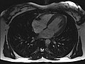
MRI of the human heart, four-chamber view; Animated version

MRI of the human heart, sagittal view; Animated version

MRI of the ankle joint in T1 weighting

Open magnetic resonance tomograph at the Clinic for Diagnostic Radiology at the Magdeburg University Hospital
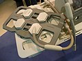
Magnetic resonance imaging antenna

Power supply unit


Manufacturer of MRI systems
- Agilent (before 2010 to Varian )
- Ascpect Imaging
- Aurora Imaging Technology, Inc.
- Bruker (high field research tomograph)
- Canon Medical Systems (formerly Toshiba )
- Esaote (low field tomograph with permanent magnet for extremity diagnostics)
- Fonar Corp., in Europe through Tecserena
- GE Healthcare
- Hitachi Medical Systems
- Ningbo Xingaoyi Magnetism (XGY)
- Paramed Medical Systems (MROpen)
- PhiHealth (partnership with Cerner Corporation )
- Philips
- Siemens Healthineers
- Time Medical Holdings Company Limited
- United Imaging
Data format
The DICOM standard has largely established itself for the storage and archiving of the results of medical imaging procedures . After the examination, the patient is often given a data carrier (e.g. CD-ROM or DVD-ROM ) with his own sectional images , which he then passes on to the attending physician. Often times, these images are not converted to a more common graphic format such as. B. JPEG converted so that the patient needs a separate viewing program to view. Often there is one on the data carrier which, in addition to displaying the DICOM images, may also offer additional functions such as measurements or magnifying glass tools.
literature
- Peter A. Rinck: Magnetic Resonance in Medicine. The Basic Textbook of the European Magnetic Resonance Forum . 8th edition. The Round Table Foundation, 2014 ( magnetic-resonance.org ).
- Olaf Dössel: Imaging procedures in medicine. From technology to medical application . Springer, Berlin 2000, ISBN 3-540-66014-3 .
- Heinz Morneburg (Hrsg.): Imaging systems for medical diagnostics . 3. Edition. Publicis MCD, Munich 1995, ISBN 3-89578-002-2 .
- Donald W. McRobbie, Elizabeth A. Moore, Martin J. Graves, Martin R. Prince: MRI from Picture to Proton . Cambridge University Press, Cambridge 2002, ISBN 0-521-52319-2 .
- Fritz Schick: MRI sequences . In: The Radiologist . tape 9 . Springer, 2006, ISSN 0033-832X .
- Maximilian Reiser , Wolfhard Semmler (Ed.): Magnetic resonance tomography . Springer, Berlin 1997, ISBN 3-540-61934-8 .
- Wolfgang R. Nitz, Val M. Runge, Stuart H. Schmeets, William H. Faulkner, Nilesh K. Desai: Practical course MRT . Instructions on MRI physics via clinical image examples. Thieme, Stuttgart 2007, ISBN 978-3-13-139721-8 .
- Christoph Zink, Christoph U. Herborn: Clinic Dictionary MRT . ABW, Berlin 2007, ISBN 978-3-936072-57-0 .
- Roland Tammer, Sabine Hofer, Klaus-Dietmar Merboldt, Jens Frahm: Magnetic Resonance Imaging of the Rhesus Monkey Brain . Vandenhoeck & Ruprecht, Göttingen 2009, ISBN 978-3-525-40424-9 .
- Lothar Dilcher: manual of magnetic resonance tomography . Texts to get you started, diagrams to help you think, formulas for those interested. 3rd, revised edition. E. Ferger Verlag, Bergisch Gladbach 2004, ISBN 3-931219-21-6 .
- Simon, Merrill, Mattson, James S: The pioneers of NMR and magnetic resonance in medicine: The story of MRI . Bar-Ilan University Press, Ramat Gan, Israel 1996, ISBN 0-9619243-1-4 .
- Haacke, E Mark, Brown, Robert F, Thompson, Michael, Venkatesan, Ramesh: Magnetic resonance imaging: Physical principles and sequence design . J. Wiley & Sons, New York 1999, ISBN 0-471-35128-8 .
- P Mansfield: NMR Imaging in Biomedicine: Supplement 2 Advances in Magnetic Resonance . Elsevier Science, Oxford 1982, ISBN 978-0-323-15406-2 .
- Eiichi Fukushima: NMR in Biomedicine: The Physical Basis . Springer Science & Business Media, 1989, ISBN 978-0-88318-609-1 .
- Bernhard Blümich, Winfried Kuhn: Magnetic Resonance Microscopy: Methods and Applications in Materials Science, Agriculture and Biomedicine . Wiley, 1992, ISBN 978-3-527-28403-0 .
- Peter Blümer: Spatially Resolved Magnetic Resonance: Methods, Materials, Medicine, Biology, Rheology, Geology, Ecology, Hardware . Ed .: Peter Blümler, Bernhard Blümich, Robert E. Botto, Eiichi Fukushima. Wiley-VCH, 1998, ISBN 978-3-527-29637-8 .
- Zhi-Pei Liang, Paul C. Lauterbur: Principles of Magnetic Resonance Imaging: A Signal Processing Perspective . Wiley, 1999, ISBN 978-0-7803-4723-6 .
- Franz Schmitt, Michael K. Stehling, Robert Turner: Echo-Planar Imaging: Theory, Technique and Application . Springer Berlin Heidelberg, 1998, ISBN 978-3-540-63194-1 .
- Vadim Kuperman: Magnetic Resonance Imaging: Physical Principles and Applications . Academic Press, 2000, ISBN 978-0-08-053570-8 .
- Bernhard Blümich: NMR Imaging of Materials . Clarendon Press, 2000, ISBN 978-0-19-850683-6 .
- Jianming Jin: Electromagnetic Analysis and Design in Magnetic Resonance Imaging . CRC Press, 1998, ISBN 978-0-8493-9693-9 .
- Imad Akil Farhat, PS Belton, Graham Alan Webb, Royal Society of Chemistry (Great Britain): Magnetic Resonance in Food Science: From Molecules to Man . Royal Society of Chemistry, 2007, ISBN 978-0-85404-340-8 .
Web links
- Introduction to the basics of magnetic resonance imaging E-learning website from EMRF (European Magnetic Resonance Forum) / TRTF (The Round Table Foundation), in English.
- Technical aspects of magnetic resonance tomography: gradient echo sequence, frequency coding and displacement artifacts (numbered fig., Including formula of the Fourier transformation)
- Explanation and animation on magnetic resonance tomography ( memento from March 29, 2007 in the Internet Archive ) at Quarks & Co
- The Basics of MRI
- A short history of magnetic resonance imaging from a European point of view ( Memento from December 10, 2002 in the Internet Archive )
- An Excursion into the History of Magnetic Resonance Imaging (English)
- Chris Rorden: MRIcro software for displaying and analyzing MR images .
- MRI in use (English)
- Learning script basics of magnetic resonance imaging . (PDF) Diagnostic and Interventional Radiology, University Hospital Gießen and Marburg, Marburg site
- Educational game on nobelprize.org (English)
- Flash animations that clearly explain the physics (English)
Individual evidence
- ↑ Learning script basics of magnetic resonance imaging . (PDF) Diagnostic and Interventional Radiology, University Hospital Gießen and Marburg, Marburg site
- ^ Cornelius Borck: magnetic resonance imaging. In: Werner E. Gerabek , Bernhard D. Haage, Gundolf Keil , Wolfgang Wegner (eds.): Enzyklopädie Medizingeschichte. De Gruyter, Berlin / New York 2005, ISBN 3-11-015714-4 , p. 733.
- ^ Paul Christian Lauterbur: Image Formation by Induced Local Interactions: Examples of Employing Nuclear Magnetic Resonance . In: Nature . 242, No. 5394, 1973, pp. 190-191. bibcode : 1973Natur.242..190L . doi : 10.1038 / 242190a0 .
- ^ PA Rinck: The history of MRI . In: Magnetic Resonance in Medicine, 8th edition; . 2014.
- ↑ E. Odeblad, G. Lindstrom: Some preliminary observations on the proton magnetic resonance in biological samples . In: Acta Radiologica . 43, 1955, pp. 469-476.
- ↑ A. Geiger, M. Holz: Automation and Control in high power pulsed NMR. In: J. Phys. E: Sci.Instrum. 13, 1980, pp. 697-707.
- ^ Cornelius Borck: magnetic resonance imaging. 2005, p. 733.
- ^ Lars G. Hanson: Is Quantum Mechanics necessary for understanding Magnetic Resonance? In: Concepts in Magnetic Resonance Part A , Volume 32A, No. 5, 2008, pp. 329-340, doi: 10.1002 / cmr.a.20123 , drcmr.dk (PDF; 515 kB).
- ↑ WD Rooney et al. a .: Magnetic field and tissue dependencies of human brain longitudinal 1H2O relaxation in vivo. In: Magn. Reson. Med. Vol. 57, 2007, pp. 308-318. PMID 17260370 ; doi: 10.1002 / mrm.21122
- ↑ 7-Tesla ultra-high field magnetic resonance tomograph, brain research. Retrieved July 21, 2020 .
- ↑ 9.4 Tesla small animal scanner at the Leibniz Institute for Neurobiology. Retrieved April 24, 2019 .
- ↑ Welcome to the Erwin L. Hahn Institute. Retrieved July 21, 2020 .
- ↑ Institute for Biomedical Engineering (IBT) at ETH Zurich .
- ↑ Press release from Philips on the 7 Tesla MRI in Zurich ( memento from July 19, 2011 in the Internet Archive ).
- ↑ Journey into the Brain - The New Magnetic Resonance Center. Max Planck Institute, 2019, accessed on July 21, 2020 .
- ^ High-field MRI at the University of Vienna .
- ↑ Multi- million dollar contract for 7 Tesla magnetic resonance tomographs signed (PDF; 106 kB).
- ↑ Ultra-high field MRT working group at the DKFZ in Heidelberg ( Memento from February 20, 2009 in the Internet Archive ).
- ↑ Press release from the DKFZ in Heidelberg on the 7-Tesla whole-body MRI .
- ↑ Press release from the MDC in Berlin on the 7-Tesla whole-body MRI
- ^ High-field MRI at the MDC in Berlin
- ↑ 9.4 Tesla MR-PET at the Jülich Research Center .
- ↑ Press release from FAU Erlangen-Nürnberg , accessed on October 20, 2015.
- ↑ Press release of the University Hospital Erlangen , accessed on October 20, 2015.
- ^ Heart center opened at the Würzburg University Hospital. Retrieved October 4, 2017 .
- ^ DZNE Bonn Methods. Retrieved August 19, 2020 .
- ↑ Magnetic resonance tomograph pulls to the Venusberg - 40 tons on the hook. Retrieved August 19, 2020 .
- ↑ NEURO SPIN: From Physics to the Human Brain , accessed on May 29, 2013.
- ↑ Information sheet on superconducting magnets - MRI. (PDF) Fire Department Munich, professional fire brigade, 2009, archived from the original on May 9, 2010 ; Retrieved April 4, 2015 .
- ↑ S. Yilmaz, M. Misirlioglu: The effect of 3 T MRI on microleakage of amalgam restorations. In: Dento maxillo facial radiology. Volume 42, number 8, 2013, p. 20130072. doi: 10.1259 / dmfr.20130072 . PMID 23674614 . PMC 3756742 (free full text).
- ↑ Products | St. Jude Medical. Retrieved February 28, 2018 .
- ↑ S. Nospes, W. Mann, A. Keilmann: magnetic resonance imaging in patients with magnet powered hearing implants. In: Der Radiologe , 2013, pp. 1026-1032, doi: 10.1007 / s00117-013-2570-x .
- ^ Bert Hansky: Special MRI-compatible electrodes . In: Deutsches Ärzteblatt Int. tape 109 , no. 39 , September 28, 2012, p. 643–644 , doi : 10.3238 / arztebl.2012.0643b .
- ↑ SureScan. ClinicalTrials.gov
- ↑ ProMRI. ClinicalTrials.gov
- ↑ Nicola Siegmund-Schulze: MRI examination during pregnancy: Contrast media can damage the child at any time Deutsches Ärzteblatt 2016, Volume 113, Issue 44 of November 9, 2016, page 1987
- ↑ LL Tsai, AK Grant et al. a .: A Practical Guide to MR Imaging Safety: What Radiologists Need to Know. In: Radiographics: a review publication of the Radiological Society of North America, Inc. Volume 35, Number 6, October 2015, pp. 1722-1737, doi : 10.1148 / rg.2015150108 , PMID 26466181 (review).
- ↑ Martina F. Callaghan, Clive Negus, Alexander P. Leff, Megan Creasey, Sheila Burns, Janice Glensman, David Bradbury, Elaine Williams, Nikolaus Weiskopf: Safety of Tattoos in Persons Undergoing MRI. In: New England Journal of Medicine. 380, 2019, p. 495, doi : 10.1056 / NEJMc1811197 .
- ^ Schedule of Fees for Doctors, Item O III: Magnetic resonance imaging
- ↑ hil: MRI is the most common in Germany according to the Barmer doctor report. In: aerzteblatt.de . February 1, 2011, accessed December 27, 2014 .