
Magnetic core


A magnetic core , also called magnetic core or, according to the historical development, also called iron core , is a component from which an electrical or electronic component , an inductance , can be produced together with electrical conductors and mechanical parts .
The magnetic core, together with an electrical conductor, forms an inductance ( coil , transformer , etc.).
Magnetic cores consist of a soft magnetic material with the highest possible saturation magnetic flux density and high magnetic permeability . As a result, the magnetic flux that arises when current flows through the electrical conductor of the coil is bundled and guided with little loss and the inductance is increased. A high permeability increases the magnetic field of an inductor by up to five powers of ten compared to an inductor with air as the core, which means that the dimensions of the inductor with a magnetic core can be smaller than with an air-core coil.
The materials used for magnetic cores are either ferromagnetic metal alloys , mostly in the form of sheet metal or foil ( electrical sheet , metallic glass ) or bonded powder ( powder core ), or oxide-ceramic ferrimagnetic materials ( ferrites ) are used ( ferrite core ).
The losses that occur with alternating current are decisive for the use of materials for magnetic cores. The so-called iron or core losses have two components:
- A low residual magnetism is a prerequisite for low-loss remagnetization in alternating current operation .
- The eddy current losses are reduced in cores made of electrical steel stacks by insulated sheets.
Unlheeted (solid) iron cores can only be used for direct current applications (e.g. electromagnet ).
Ferrite cores have eddy current losses that are a few powers of ten lower than iron cores, since as metal oxides they conduct electricity poorly. The same applies to powder cores - here metal powder particles are isolated from one another.
Magnetic cores made of sheet metal are mainly used for low-frequency ( mains frequency up to a few kHz) applications and large and very large outputs up to the megawatt range. In terms of the mass used, electrical sheet cores cover about half of the market for magnetic cores. They are characterized by scalable sizes, which range from small power transformers the size of a matchbox to transformers and electric motors to power plant generators. The eddy current and hysteresis losses are disadvantageous.
Ferrite cores are the most frequently used magnetic cores for inductances due to the elimination of eddy current losses, adjustable properties, diverse designs and low costs in terms of quantity. They are mostly used for higher frequencies and powers below about 10 kW and are therefore preferred in electronic devices. Examples are power supplies for notebooks , tablets , smartphones and LED lamps or welding inverters. The maximum size, which is limited by the manufacturing process of the ferrite cores, is countered by series or parallel connection.
Powder cores are used when a lot of magnetic energy has to be stored at high frequencies in a small installation space - e.g. B. for toroidal storage chokes .
For special applications such as For example, in shaded pole motors with synchronous operation, magnetic cores made of mixed soft and hard magnetic materials are also used.
General information
Differentiation from hard magnetic materials

In a soft magnetic core made of a ferromagnetic or ferrimagnetic material, a low field strength can cause a large electromagnetic induction with a high magnetic flux density (also called induction). This behavior is a material property and leads to a magnetization of the core material. Even with soft magnetic materials, however, a residual magnetization (remanence) remains after the field is switched off , which can be reset by means of an opposing field strength, the so-called coercive field strength . A coercive field strength of 1000 A / m was defined as the boundary between soft and hard magnetic materials.


Depending on the material, soft magnetic materials can be magnetized up to a saturation polarization of about 2.3 Tesla (T) .

Important parameters of magnetic cores
When using magnetic cores in inductors, the following magnetic and electrical parameters must be taken into account in addition to the mechanical dimensions:
- Magnetic flux density at saturation or the saturation magnetization or saturation induction of the material in Tesla (T)
- Remanence is the residual magnetization that remains in the material after the field has been switched off
- Magnetic field strength of the applied field in A / m
- Coercive field strength , this is the magnetic field strength that is necessary to completely remove remanence from the material
- Permeability (magnetic conductivity of the core material), represented as absolute permeability or by the permeability number (previously called relative permeability)
- the resistivity of the core material in
- the specific iron or core losses in W / kg or W / cm³ for one or more frequencies.


All electrical and magnetic properties are dependent on the material, frequency and temperature, and also age-dependent, especially in the case of powder cores exposed to high temperatures.
Permeability and hysteresis
In a magnetic circuit , the magnetic core is the conductor of magnetic flux in analogy to the metallic conductor in an electrical circuit , whereby the permeability, the magnetic conductivity of the respective material, is the analogue of the electrical resistance.
The magnetic permeability (also magnetic conductivity) is a material property that determines the permeability of the material for the magnetic field . In other words: the permeability determines the magnetization of a material by an external magnetic field. The permeability results from the material-dependent permeability number (formerly also referred to as relative permeability) divided by the magnetic permeability of the vacuum


Due to the low numerical value of the magnetic permeability of the vacuum, represented in SI units , the constants and for a material also differ in the typical order of magnitude of their numerical values. Example: sheet iron: , .


The magnetic permeability is determined by dividing the flux density in the magnetic core and the associated field strength :

This relationship is in practice a complex issue: If around the magnetic core an external magnetic field is constructed by an encircling coil of an electric current is flowed through, then the core is indeed magnetized, but the variation of the magnetization is linear only in small areas. This course of the magnetic flux density or induction with changes in the applied field is shown in a magnetization curve. When the magnetization is reversed, the curve becomes a so-called hysteresis loop .
The hysteresis loop shows that the permeability is not linear. The numerical value of the permeability depends on the reference point on the magnetization curve. Different definitions of permeability are used depending on the application. For technical applications it is defined in the standard with different reference points. Two definitions of this are drawn in the picture above on the right, the initial permeability , which results from the initial magnetization curve, and the maximum permeability , which indicates the beginning of saturation. Up to this point the permeability is approximately linear. Outside of this range, the material saturates and the permeability decreases sharply.


Depending on the material, soft magnetic cores have permeability numbers that are up to 4 to 5 powers of ten greater than that of air. As a result, the magnetic flux is concentrated in a small core cross-section and can be directed to where it should work. In general, this enables a smaller size of inductors. In the case of transformers, a smaller number of turns in the primary coil is also possible.
Hysteresis loops - form and application
The form of hysteresis loops enables certain applications:
 |
Round hysteresis R loops are created when no preferred magnetic direction dominates the material. A characteristic is a ratio of remanence to saturation induction of . R loops are required for bipolar control with the highest permeability, for example in current transformers for residual current circuit breakers , ISDN transformers or current-compensated radio interference suppression chokes . |
 |
Rectangular hysteresis Z loops have a remanence ratio of . The initial permeability is low and the maximum permeability is high. Z loops are required if a small change in field strength is to result in a sudden change in induction or impedance. Examples are switching cores, transductor chokes, high-permeability bipolar converters and transformers as well as security labels. |
 |
Flat hysteresis F-loops have a central area of constant slope with low remanence and an almost constant permeability level. F-loops are required for low-distortion signal transmissions or increased DC tolerance, for example in storage chokes, current-compensated chokes, signal transmitters with DC tolerance, current transformers or instrument transformers. |


Influence of the magnetic properties through heat treatment

Magnetic cores, which consist of laminated sheet metal stacks of soft magnetic alloys, usually require a special aftertreatment to achieve the desired magnetic properties. B. express in the form of the hysteresis loop. With a few exceptions, these sheets must be subjected to a heat treatment, because these materials are usually melted under vacuum and then usually cooled in an uncontrolled manner. As a result, the material initially has relatively undefined magnetic properties. The magnetic properties can also change during further processing of the metal sheets through punching, cutting or deformation.
The desired magnetic properties of the material can be set by means of a heat treatment. This heat treatment, known as annealing or final annealing, is carried out at an alloy-specific temperature in the softening and recrystallization range of the metal, which is between 800 ° C and 1200 ° C. Depending on the alloy and application of the material, the final annealing can also be carried out under vacuum or inert gas. The “magnetic final annealing” changes the mechanical or magnetic properties in such a way that, on the one hand, mechanical tension and structural changes are healed and, on the other hand, a defined magnetic “basic state” is brought about. This final annealing can either be carried out by the manufacturer of the material or by the user.
Powder cores and ferrite cores are provided with the desired and specified properties at the manufacturer and therefore do not need to be post-treated by the user.
Limit of magnetizability, saturation induction

With ferromagnetic materials there is a material-specific maximum value of the magnetization, which is called saturation induction , saturation magnetization or saturation polarization and cannot be increased by increasing the external magnetic field strength. The reason for the magnetic saturation is that the Weiss areas of the soft magnetic material are completely aligned with a certain external magnetic field. The induction of saturation is associated with the decrease in permeability. This behavior has effects on the secondary waveform for transformers or transmitters; it is distorted, creating harmonics that can lead to electromagnetic interference . In the picture on the right, these distortions can be recognized by the non-sinusoidal waveform of the outgoing signal.
Sometimes core saturation can be accepted (e.g. saturation choke ), in special cases the resulting harmonics are even desired and required (e.g. fluxgate magnetometer , article surveillance label ). Usually, however, saturation should be avoided if possible.
Distortion of the secondary waveform can be prevented by reducing the magnetic conductivity in the magnetic circuit. This usually takes place with an interruption of the magnetic core material by an air gap , which reduces the permeability.
Shear, reduction in permeability through an air gap

A magnetic flux flows through the magnetic core of an inductance in a closed magnetic circuit . It is - analogously to the electric current - the sequence of the magnetic voltage , which is proportional to magnetic field strength , and flows through a magnetic resistance in analogy to Ohm's law .


- With


where is the length of the magnetic circuit and the area of the core cross-section.


Until the core material is saturated, it can be assumed that the permeability , which determines the magnitude of the magnetic resistance, is approximately linear and has a constant value, as a result of which the magnetic circuit has a constant magnetic resistance. When saturation is reached, the permeability then becomes smaller, the magnetic resistance increases and even if the magnetic field increases further, the magnetic flux no longer increases. This leads to the distortions shown above, for example.
If a second magnetic resistance in the form of an air gap with the value is introduced into the magnetic flux, the two magnetic resistances add up to a total resistance and the magnetic flux is reduced while the field strength remains the same.


An air gap is the distance between two opposing surfaces within the magnetic core that guides the magnetic flux. It can be introduced deliberately and intentionally in order to be able to transmit higher power in switching regulators or flyback converters , for example , in order to avoid magnetic saturation in the case of premagnetization, or it is a necessary part of the construction of rotating electrical machines.

The magnetic resistances of a magnetic circuit with an air gap can be determined with the help of the respective permeability . If one divides the permeability of the calculated total magnetic resistance by the permeability of the magnetic core , the result is the shear factor . The permeability is also referred to as “sheared permeability”.


The “shear” of the permeability through an air gap causes a reduction in the core permeability and leads to a flattening and linearization of the hysteresis curve without influencing the remanence or the coercive force. However, it must be accepted that the dimensions of the core must be larger, since the magnetic flux is reduced by the shear given the same field strength.
A substantial part of the magnetic energy is stored in the air gap of storage chokes. For this, it must be accepted that the inductance per number of turns (so-called Al value) is reduced.
Magnetic materials made from powder materials, iron powder and ferrite cores, consist of individual, electrically separated ferromagnetic or ferrimagnetic elementary magnets, which means that these materials have individual "air gaps" between the particles; one also speaks here of a distributed air gap. Here, too, the magnetic flux between the magnetic particles is interrupted, so that the effective permeability is lower than with a material without an air gap. The size of this "distributed air gap" depends on the pressure with which the powder was pressed during manufacture.
DC bias
A magnetic core is premagnetized when, for operational reasons, a direct current flows through the coil of an inductance or a direct current is superimposed on the alternating current flowing through the coil. The pre-magnetization causes a constant magnetic flux in the magnet core, which reduces the controllable range until the material is saturated. The saturation of the core due to the premagnetization can be prevented by an air gap. This applies to both laminated electrical steel sheets and powder or ferrite cores. However, due to their design, powder cores contain a so-called distributed air gap, so that a gap-shaped air gap is rarely used here. The air gap leads to a flattening and linearization of the hysteresis curve and expands the controllable range until saturation occurs.
Since no eddy currents occur with direct current, z. B. pole pieces of externally excited electrical machines are made of solid metal. Often these cores are still made from electrical steel.
The cores of relays operated with direct current are not laminated, but the cores of relays operated with alternating current (mains frequency) are also often made of solid metal, since the flux densities are low here. The pole shoes have a shaded-pole short-circuit winding to avoid zero crossing of the attraction force .
Iron losses, core losses
In the operation of magnetic cores, losses occur due to the changing polarity of the magnetic field in the core, which are known as iron losses or core losses . They are the sum of the hysteresis losses , also known as polarity reversal losses , the eddy current losses , the excess or additional losses and the after-effects losses .
The iron losses depend on parameters such as material properties, material thickness, frequency, temperature and the local flow conditions. They are specified in the manufacturers' data sheets for electrical steel in W / kg core material for a fixed flux density, direction of flow and frequency. Depending on the iron quality and sheet thickness, the specific iron losses are between 0.8 and 12 W / kg at a flux density of 1.5 T and a frequency of 50 Hz.
For powder cores and ferrite cores, the losses are usually not given in W / kg, but in W / cm³. An estimate of these losses can be found in the tables of publications.
The iron losses or core losses are only the proportion of the losses of the magnetic core of an inductance. The copper losses must also be added to the total losses of an inductance.
Hysteresis losses

A ferromagnetic material is magnetized by aligning the elementary magnets in parallel in the Weiss areas, depending on the applied field strength. The Weiss domains change the direction of their polarization in their domains and some domains with the same polarity enlarge at the expense of neighboring domains. Overall, this results in a magnetization in the magnetic cores that runs approximately parallel to the external field.
Since the magnetic cores are mainly used to guide alternating magnetic fields, the process of magnetization reversal takes place twice with each passage of an alternating current wave. This is illustrated with a hysteresis curve. Energy is consumed in these polarizations. The losses are caused by the work that has to be done to reverse the polarity of the elementary magnets in the core material in the rhythm of the frequency. These losses, which are converted into heat when the polarity is reversed, correspond to the area enclosed by the hysteresis curve and are therefore called hysteresis losses. Since the hysteresis losses occur with every run of the hysteresis curve, they are linearly frequency-dependent. They increase quadratically with the magnetic flux density.
Eddy current losses

Eddy current is a current that is induced in a magnetic core in a magnetic field that changes over time. Eddy currents heat the core material and lead to losses even at low frequencies (50/60 Hz). As a measure against eddy current losses, the magnetic cores of transformers and electric motors are not made solid, but laminated, "laminated" . These stamped or cut electrical steel sheets are coated with a heat-resistant and insulating varnish and oriented parallel to the magnetic field lines are layered to form blocks or rolled to form rings. The magnetic flux is thus distributed over individual, separate fluxes in the individual metal sheets, in which only smaller eddy currents can develop, the power loss of which is significantly lower overall than in a solid material. The sheets are usually thinner than 1 mm. The thinner the sheet, the lower the eddy current losses and the higher the operating frequency.
Laminated magnetic cores are only used in the range of low frequencies from 16 to 400 Hz, with output transformers also in the entire low frequency range up to 20 kHz. Since the eddy current losses increase quadratically with the frequency, they limit the frequency range up to which the material can be used in the case of unsuitable materials due to excessive losses. However, wound tape cores with a tape thickness of around 20 µm can be used up to 100 kHz. At frequencies in the high frequency range, however, powder cores or ferrites are predominantly used for cores of transformers, coils and chokes. Ferrites have a high specific electrical resistance, in powder cores there are electrically separated ferromagnetic particles with dimensions in the micrometer range. Although eddy currents arise, they are of subordinate importance compared to the hysteresis losses.
Excess or additional losses
The excess or additional losses are attributed to the energy demand that arises when magnetizing magnetic elements through the displacement of the Bloch walls. For high inductions, they are negligible compared to the hysteresis and eddy current losses.
After-effects losses
The aftereffect losses record the lag of induction behind a previous field change due to delays in the turning processes of magnetic elements. For high inductions, they are negligible compared to the hysteresis and eddy current losses.
Filling level
The degree of filling of a magnetic core is the ratio of the magnetizable material in the core to a core made of solid material. With laminated sheet metal cores and powder cores, this ratio is always <1. Since the flux density is related to the number of magnetizable elementary magnets, the saturation flux density with laminated cores and powder cores is always smaller than with a full material, depending on the degree of filling.
Magnetostriction
Magnetostriction is the mechanical deformation of magnetic materials as a result of an applied magnetic field. By rotating the dipoles in Weiss's domains as a result of the applied field, the body experiences an elastic change in length at constant volume. Values in the range from approx. 1 to 30 ppm are usual . Magnetostriction is desirable in some applications (e.g. retail security label ), but mostly, u. a. because of noise development, undesirable.
Inductance calculation
To calculate the inductance (choke, filter coil, transformer), the permeability and the geometric parameters of the core are required.This is because and only possible because or when the permeability number is high compared to air - only then will the magnetic flux be largely in the core guided. Manufacturers give the following values for their ferrite cores or powder cores:
- effective length of the magnetic circuit
- effective core cross-section
- Permeability number , mostly for a specific frequency and flux density


The presence and size of an air gap make the calculation more complicated - the magnetic resistances of the gap and the core must be considered separately. If the air gap is small, its effective area is that of the core.
Several manufacturers offer models for calculating inductance on the Internet:
- Online calculator
- Epcos
- TDK Epcos
- Fericor
- experts
- Walter, calculation of the winding goods
For specific cores made of ferrite or powder, a so-called value can be determined or specified. It makes the inductance calculation much easier. The value is usually given in (nH / N 2 ) (nanohenry per turn squared) and is the reciprocal of the magnetic resistance .

The core geometry and the permeability figure are taken into account in the value. If you wind a core with a known value with turns, you get a coil with the inductance:


Accordingly, one can also determine the value of unknown cores or core constructions by measuring the inductance of a test winding made of turns:

This method is hardly suitable for iron cores because the value of the initial permeability deviates significantly from the mean operating value.
The calculation only applies if the core material is operated in a linear range of its characteristic curve consisting of induction and magnetic field strength or remains below the saturation induction. It must be noted that even then, and therefore the value, depends on the frequency and flux density.

Air gaps reduce the value, but allow a higher magnetic flux up to core saturation.
Core materials

The most important commercial soft magnetic core materials or materials are:
- Solid material
- Laminated sheets
- Silicon- iron alloys (SiFe), electrical sheet and steel
- Nickel- iron alloys (NiFe), (Mu-Metal, Permalloy)
- Cobalt- iron alloys (CoFe)
- Aluminum- iron alloys (Alperm)
- Amorphous or nanocrystalline metallic glass
- Powder cores
- Iron powder cores (carbonyl iron)
- Nickel-iron powder cores (NiFe), (MPP, High-Flux)
- Silicon-iron powder cores (SiFe), ( Sendust , Kool Mµ)
- Ferrite cores (Ferroxcube)
- Manganese-zinc-ferrites (MnZn)
- Nickel-zinc-ferrites (NiZn)
Overview of the material properties of soft iron and laminated iron alloys
The following table gives an overview of the material properties of soft iron and lamellar iron alloys. The numerical values should be used with caution, as the permeability of ferromagnetic materials varies greatly with the field strength. For example, 4% Si steel has a permeability number of 2000 (close to 0 T) and a maximum of 35,000. In addition, the numerical values vary greatly with the composition of the alloys and the respective thermal post-treatment of the material.
| material | Saturation induction B S (T) |
Permeability µ r , µ i |
Curie temperature (° C) |
Specific resistance ρ (µΩ · cm) |
Trade name manufacturer |
|---|---|---|---|---|---|
| Iron cores, solid material | |||||
| Soft iron | <2.15 | 3,500 ... 12,000 | 770 | 51 | ARMCO irons |
| Laminated metal cores | |||||
| SiFe alloy sheet, Si 3… 4% |
1.7 ... 2.03 | 7,000 ... 35,000 | 750 | 40 ... 48 |
Electrical sheet, Carlite Trafoperm, Vacofer |
| NiFe alloy sheet, Ni 72 ... 80% |
0.7 ... 0.8 | 50,000 ... 500,000 | 360… 430 | 55 ... 60 |
Mu-metal , Permalloy, Supermalloy, Cryoperm, Ultraperm, Vacoperm, |
| NiFe alloy sheet, Ni 54 ... 68% |
1.2 ... 1.5 | 50,000 ... 150,000 | 400 | 45 | Permax |
| NiFe alloy sheet, Ni 36 ... 50% |
1.5 ... 1.6 | 50,000 ... 135,000 | 250 ... 440 | 60 | Permenorm, Megaperm, Ortonol |
| Co-Fe alloy sheet Co 49% |
≤2.3 | 3,500 ... 18,000 | 800… 950 | 15… 79 | Vacodur, Vacoflux, Permendur, Fernico |
| AlFe alloy sheet Al 10 ... 17% |
0.8 | 55,000 | 500 | - | Alperm, Alfenol, Alfer. |
| Amorphous metallic glass |
0.41 ... 1.56 | 1,100 ... 1,000,000 | 150 ... 399 | 120 ... 140 | Metglas, Vitrovac |
| Nano-crystalline metallic glass |
1.2 ... 1.23 | 10,000 ... 200,000 | 570 ... 600 | 120 ... 140 | Finemet, Nanoperm, Vitroperm |
Iron cores, solid material
Unalloyed, solid soft iron

Soft iron (annealed iron) is a soft magnetic material and consists of unalloyed iron with a high degree of purity and is known under the trade name ARMCO iron . It is produced either from powder using a sintering process or using a melting process in a vacuum and is the cheapest core material. It is characterized by a high saturation magnetization of approx. 2.15 Tesla , a higher Curie temperature , which also allows use at higher temperatures, and a relatively low coercive field strength , so that only a small residual magnetism in the iron after the external magnetic field has been switched off remains. It can be used when a temporary magnetization by an external magnetic field should not lead to permanent magnetization.

Soft iron has the disadvantage of good electrical conductivity for magnetic cores . As a result, the eddy current losses occurring in the alternating field can become large and heat a massive core made of soft iron. Since no eddy currents occur with direct current, the use of solid soft iron is limited to, for example, direct field yokes with direct current pre -magnetization, magnetic pole pieces, armature bodies, relay parts, flux guide plates and relays . Unalloyed soft iron also plays a role in magnetic shields .
Laminated metal cores
General
.jpg)
Iron - silicon alloys were the first soft magnetic materials used for power generators, transformers and electric motors in the 19th century. The addition of silicon to the iron leads to an increase in the specific electrical resistance of the core material, as a result of which the eddy current losses compared to unalloyed soft iron are reduced. Carbon is of great importance in the alloy composition. Even small amounts of it lead to an aging of the magnetic properties, they deteriorate. For this reason it is necessary to keep the carbon content in the electrical steel sheet as low as possible.
The alloys commonly used today are summarized under the standard term electrical sheet . Other common terms are dynamo sheet, transformer sheet, motor sheet and electrical steel .
Layered or coiled and mutually insulated electrical sheets as magnetic cores are mainly used in the range of the mains frequency (50/60 Hz) and other low-frequency alternating currents for the transmission of higher powers .
FeSi alloys (electrical steel)

Electrical sheet consists of an iron-silicon alloy of high-purity, low-carbon iron with additions of about 1 to about 4% silicon and small amounts of other alloying elements such as e.g. B. aluminum and manganese with up to 0.5%. A silicon concentration above 4% affects the mechanical properties of the material; it becomes brittle, causes difficulties in rolling and is therefore not used for electrical steel sheets. The proportion of carbon is usually below 0.005%.
Electrical sheet is produced from the melt using hot rolling, cold rolling and annealing processes. The material is rolled into thin sheets in the thickness range between 0.18 and 1 mm. The sheets are then usually coated with a 1 to 3 μm thick, often annealing-resistant insulation for electrical insulation. Then punching parts or strips are made from the sheet metal by punching or cutting, from which the iron cores for motors or transformers and chokes are packaged or wound.
The construction of the iron cores, stator or armature stacks from stamped parts that are insulated from one another reduces eddy current losses. Punching changes the magnetic properties in the area of the cut edges due to internal stresses, but the original properties can be restored by annealing (final annealing ) at approx. 800 ° C.
With 2.03 T, electrical steel sheets have a very high saturation magnetization with relatively low residual magnetization, so that the magnetic reversal losses are low. They are mainly used for power conversion at mains frequency with flux densities between 1.5 and 1.8 T.

Electrical steel is standardized and described in a list with material numbers. According to its properties, it is divided into isotropic , non- grain-oriented (NO electrical steel ) and anisotropic , grain-oriented (KO electrical steel) materials.

Non-grain-oriented, isotropic magnetic materials (NO electrical steel) are equally magnetizable in all directions. The ideal structure for an isotropic electrical steel is a polycrystalline structure with grain sizes between 20 and 200 μm, whereby the crystallites are randomly aligned with the surface in the plane of the sheet. The development of a sufficient isotropy of the magnetic properties of the NO electrical steel is significantly influenced by the design of the hot forming , cold forming and final annealing . NO electrical strips are mainly used in rotating electrical machines in which the direction of the magnetic field changes.
Grain-oriented, anisotropic materials (KO electrical steel, textured sheet) have a preferred direction of magnetizability with a higher saturation flux density, which is generated by several successive rolling and annealing treatments. This targeted anisotropy, i. H. Due to the uniform magnetic orientation of the crystallites, the magnetic reversal losses in the core are reduced and the permeability number increases with the corresponding direction of magnetization. Compared with NO materials, KO materials can therefore be used to manufacture, for example, transformers that have a higher degree of efficiency or a smaller size. KO electrical steel is used for power transformers, distribution transformers and high-quality small transformers, as the magnetic field in these is always in the same direction. The preferred design are coils (cut ribbon core, toroidal core). Punched sheets can be used by adding a so-called yoke reinforcement in the area where the texture does not have the correct orientation.
With an annual worldwide production of around 10 million tons, electrical steel is the most important soft magnetic material in terms of quantity and value. It is stamped or cut in many shapes and used to make magnetic cores for electrical machines , electrical generators , electric motors , transformers , relays , contactors , chokes , coils , ignition coils , electricity meters and controllable deflection magnets .


NiFe alloys (Mu-metal, Permalloy and Supermalloy)

The development of the soft magnetic nickel-iron alloys is closely related to the development of transatlantic telegraphic cables . In 1914, Gustav Elmen at Bell Laboratories developed a highly permeable nickel-iron alloy that he called permalloy, which was suitable for sheathing the conductor to increase impedance. This alloy originally consisted of 78.5% nickel and 21.5% iron without any additional additions. By adding copper , later chromium or molybdenum , this alloy was made more mechanically malleable in 1923 and used with the new trade name Mu-Metall in many overseas cables, see also Mu-Metall # History of Permalloy and Mu-Metall .
NiFe alloys with additions of copper (Cu), chromium (Cr) or molybdenum (Mo) have soft magnetic properties with low coercive field strengths and relatively low electrical conductivity. NiFe alloys are magnetically anisotropic and are mainly characterized by high permeability numbers and also by low magnetostriction .
These alloys are produced using the melting process and, after cooling, are processed into sheets, strips or wire . Stamped parts or strips are produced. Mechanical processing drastically reduces the permeability, which is why finished parts have to be annealed.
Soft magnetic nickel-iron alloys can have different compositions. They are divided into three groups based on the nickel content in the alloy. In addition to the trade names mentioned below, there are many other names such as Cryoperm, Ultraperm, Vacoperm, Recovac (group 1), Permax (group 2), Permenorm, Megaperm (group 3).
Group 1: 72 to 80% nickel
This includes the so-called mu-metal and comparable alloys with the names Permalloy and Supermalloy . They have the following alloy compositions:
- Mu-metal, permalloy: 76… 80% Ni, 15… 16% Fe, 4… 5% Cu and 2… 3% Cr or Mo
- Supermalloy: 75… 79% Ni, 16… 20% Fe and 3… 5% Mo
The alloys in the group have a saturation induction of 0.7 ... 0.8 T, a low coercive field strength and a very high relative permeability of 50,000 ... 500,000. In this group, the shape of the hysteresis loop can be varied within very wide limits. It is possible to make materials with a square loop (Z), round loop (R) and flat loop (F).
NiFe alloys of group 1 are used as core material for low-frequency - transformer , current transformer used and magnetic current sensors.
The materials, especially MuMetall, are also used as a shielding material against magnetic fields.
Group 2: 54 to 68% nickel
These alloys contain 54… 68% nickel and achieve saturation flux densities of 1.2… 1.5 T. In these alloys, a magnetic field tempering (strong magnetic field during annealing) can be used to set a preferred magnetic direction with high permeability. Ni-Fe alloys of group 2 are used as core material for summation current transformer for residual current circuit breaker , transducer used and pulse transformers.
Group 3: 36 to 50% nickel
NiFe alloys with 36… 50% nickel have a saturation flux density of up to 1.6 T. With these materials, rolling and intermediate annealing can change the structure and thus the shape of the hysteresis loops in wide areas. Group 3 Ni-Fe alloys are used as the core material for magnetic sensors, highly sensitive relays for residual current circuit breakers and electric motors with minimal losses.
CoFe alloys
Cobalt- iron alloys (CoFe alloys) such as Fernico or Kovar were originally developed for glass feedthroughs because of their low coefficient of thermal expansion . At the end of the 1930s, the Fernico alloy as a magnetic core in coils for radio reception made it possible to achieve a considerable reduction in dimensions compared to air-core coils. After the Second World War, the extremely high saturation magnetization of CoFe sheets was recognized by changing the alloy composition.
Cobalt-iron alloys with a composition of around 49% cobalt, 49% iron and additions of vanadium , niobium , chromium or manganese have the highest saturation polarization of all known soft magnetic materials with up to 2.3 T. With coercive field strengths of 40 to 200 A / m, the hysteresis losses of these materials are also in the middle range.
In addition to good mechanical properties, cobalt-iron alloys are mainly used because of their high Curie temperature of up to 950 ° C in applications with higher temperatures, for example in the engine industry and actuator technology .
CoFe alloys for magnetic cores are supplied as strips, rods, wire, stamped parts, EK cores as well as solid parts. Trade names for soft magnetic cobalt-iron alloys are u. a. Hyperco, Permendur, Phynicx, Vicalloy, Vacoflux, Vacodur.
AlFe alloys (Alperm)
Aluminum-iron alloys (Al-Fe alloys) such as Alperm , which consist of 83 to 87% iron and 13 to 17% aluminum, also have soft magnetic properties and are characterized by a particularly high mechanical hardness . Alperm was developed in 1939 by the Japanese inventors of the Sendust alloy, H. Masumoto and H. Saito, to replace nickel, which was scarce in Japan during World War II.
Alperm has a saturation magnetization of 0.8 T and a permeability of 55,000. Because of its hardness, Alperm was used in the pickup heads of tape recorders . Nowadays, the great magnetostriction of the material u. a. exploited in magnetoelastic sensors.
In addition to Alperm, the following trade names are known for soft magnetic aluminum-iron alloys: Alfenol and Alfer.
Amorphous and nanocrystalline metallic glass

The manufacture of metallic glass is a technique from the 1960s. The first soft magnetic metallic glass ribbon was developed in 1982 and used in the following years in motors and transformers where low core losses are important, see also Metallisches Glas # Geschichte .
A metallic glass is a soft magnetic alloy of metals and non-metals, which at the atomic level do not have a crystalline , but an amorphous structure. The compositions of such alloys can vary widely. Iron-based alloys typically consist of 70 to 90% iron, cobalt (Co) -based alloys consist of 75 to 90% cobalt. Both versions contain glass-forming additives of silicon and boron as well as type-specific additives of copper, nickel or niobium.

A metallic glass is created when a melt of a suitable alloy is poured through a nozzle onto a cooled, rotating copper wheel and cooled from around 1300 to 10 ° C within milliseconds. Temporal temperature decreases of up to 1,000,000 K / s are achieved. This creates a band on the wheel with an amorphous, glass-like structure made of metallic particles. The tape is around 20 to 40 µm thick and can be manufactured in widths of up to 200 mm.
This tape is provided with a thin, electrically insulating layer and then wound up into rolls. However, segments can also be punched out of the tape.

Due to the rapid cooling of the melt, the size of the elementary magnets in the resulting material has remained in the atomic range. To form a nanocrystalline state of the elementary magnets, the material is subjected to a two-stage annealing treatment. During the first glow phase at a temperature between 540 and 580 ° C, the elementary magnets grow to a grain size of around 10 to 15 nm. The grain size in this "nanocrystalline metallic glass" is stabilized by the addition of copper or niobium. Metallic glass with larger grain size of the elementary magnets, in which the grains can grow nm to about 100 is "amorphous metal" ( amorphous metal referred to).
After the first annealing phase, the strip is magnetically homogeneous and therefore isotropic; H. the magnetic properties are the same in all directions. In this state, the material has a round hysteresis loop with a polarization ratio of around 50% in connection with a high initial and high maximum permeability, which can increase to several hundred thousand. In this state, the tape is usually initially wound into tape cores in its desired shape. The second heat treatment, which is below the crystallization temperature, can then take place. During this second annealing treatment, the cores are exposed to a strong magnetic field. This field "induces" a controlled uniaxial anisotropy; H. a magnetic alignment of the elementary magnets, the direction of which depends on the orientation of the field to the strip core and also on the annealing temperature. With this second heat treatment, specific hysteresis loops can be set.

| material | Saturation induction B S (T) |
Permeability µ r , |
Curie temperature (° C) |
Magneto- striction (ppm) |
Core losses at 100 kHz (W / kg) |
Trade name |
|---|---|---|---|---|---|---|
| Amorphous, Fe-based, (Fe-Si-B) |
1.41 ... 1.56 | 20,000 ... 600,000 | 358 ... 399 | 20 ... 27 | 630 | Metglas 2605S3A, 2605SA1. |
| Amorphous, Co-based, (Co-Fe-Si-Ni-B) |
0.57 ... 0.77 | 80,000 ... 1,000,000 | 225 ... 365 | 0.5 | 36 | Metglas 2705M, 2714A. |
| Amorphous, Co-based (Co-Fe-Mo-Nb-Si-B) |
0.41 ... 1.0 | 1,100 ... 100,000 | 150 ... 485 | <0.2 | 100 ... 200 | Vitrovac. |
| Amorphous, Ni-based, (Ni-Fe-Mo-B) |
0.88 | 50,000 ... 800,000 | 353 | 12 | - | Metglas 2826MB. |
| Nano-crystalline, Fe-based, (Fe-Si-B-Nb-Cu) |
1.2 ... 1.23 | 10,000 ... 200,000 | 570 ... 600 | 0.1 | 41 ... 110 | Finemet, Nanoperm, Vitroperm. |
The manufacturing process of amorphous and crystalline metallic glass ribbons results in some excellent properties. The individual elementary magnets in the material are partially insulated from each other by the non-conductive glass-forming elements, so that the specific resistance of the material, at around 120 to 150 µΩ · cm, is around three times higher than that of electrical steel. In addition, they are very small, with crystalline metallic glass ribbons they are around 10 nm. This means that eddy current losses are lower than with other crystalline alloys, even at higher frequencies. The sometimes very high permeability of metallic glass ribbons enables high attenuation even in the range of higher frequencies with current-compensated chokes . Compared to ferrite cores, the required high impedance values can already be achieved with a lower number of turns, which can reduce copper losses. Another advantage of cobalt-based amorphous and nano-crystalline glass ribbons is the low magnetostriction of these materials, which is almost zero. As a result, mechanically insensitive and low-noise inductive components can be produced even under high loads.
Amorphous metallic and nanocrystalline metallic glass ribbons are used as magnetic cores in residual current circuit breakers, as cores for transformers with low no-load losses. and increasingly used in current-compensated chokes for EMC filters for broadband interference suppression . Magnetic cores made of metallic glass in lightweight electric motors became particularly important.
Powder cores
General

Powder cores (powder composite materials ) are ferromagnetic materials produced by powder metallurgy for magnetic cores of inductors.
During production, ferromagnetic metal grains of different alloys in the form of powder are mixed together with a suitable organic or inorganic electrically insulating binder and brought to the desired density and shape by pressing and subsequent thermal hardening. The production is completed by deburring and coating the outer insulation. The colors of the coating on powder cores are mostly used to identify the different materials and their permeabilities. However, the labeling is manufacturer-dependent.
Powder cores have a similarly high saturation induction as sheets made from the same alloy material. However, in powder cores, the individual metallic magnetic particles are isolated from one another by the binding agent, so that a so-called distributed air gap is created. This results in an internal shear of the magnetization curve, which leads to a correspondingly lower permeability compared to laminated cores. Powder cores therefore naturally tolerate a higher direct current bias. The permeability is also determined by the density of the pressed core; H. influenced by the distance between the pressed metal grains (the degree of filling ). A higher density of metal grains, which is achieved with higher pressure and a smaller proportion of binder, results in a higher permeability. The size of the metal grains pressed into cores also influences the properties of the magnetic core. The smaller the grains, the lower the eddy current losses, which enables operation at higher frequencies, similar to ferrite cores.
The maximum pressure that can be generated limits the maximum size of powder cores, so that the maximum volume is around 350 cm³. It is characterized by mechanical sensitivity to impacts and aging under high thermal loads. The cost of powder cores depends on the material and is often far higher than that of ferrite cores, but below the cost of nanocrystalline and amorphous ribbon cores.
The advantages of powder cores over lamellar metal cores are the lower eddy current losses at higher frequencies because the grains are electrically isolated from one another by the binding agent. Powder cores are therefore used wherever low mass is not important at frequencies well above the mains frequency and / or where high DC magnetic fields are superimposed.
A general comparison of the soft magnetic powder and ferrite materials used for similar applications is shown in the following table.
| material | Saturation induction B S (T) |
Permeability µ |
Rel. Core losses |
Max. Frequency (MHz) |
Rel. Costs |
Trade name manufacturer |
|---|---|---|---|---|---|---|
| Powder cores | ||||||
| Iron powder cores | 0.95 ... 1.6 | 1 ... 90 | very high | 0.5 | very low | Carbonyl iron |
| SiFe powder cores | 1.6 | 26 ... 90 | high | 0.5 | low | X-Flux, Mega Flux |
| SiAlFe powder cores | 1.0 | 14… 125 | low | 0.9 | low | Sendust, Kool Mµ |
| NiMoFe powder cores | 0.8 | 14… 550 | quite low | 2.0 | high | MPP |
| NiFe powder cores | 1.5 | 14… 160 | medium | 1.0 | medium | High flux |
| Ferrite cores | ||||||
| MnZn ferrite cores | 0.2 ... 0.5 | 300… 20,000 | low | 4.0 | very low | div. |
| NiZn ferrite cores | 0.2 ... 0.4 | 10 ... 3,500 | low | 1000 | very low | div. |
Powder cores have tolerances of the Al content of ± 8… 10%.
Powder cores are available as toroidal cores (most common form, mostly insulated, outer diameter approx. 4 to 170 mm), E cores, EF cores, EM cores, U cores, pot cores, thread spool cores and rods. Some manufacturers offer customer-specific processing.
Iron powder cores (carbonyl iron)

The vast majority of iron powder cores are made from carbonyl iron, but there are also iron powder cores made from hydrogen-reduced iron powder. Carbonyl iron is a highly pure iron that is produced by the decomposition of purified, liquid iron pentacarbonyl . It can be purified by distillation and, after its decomposition above 150 ° C, forms a particularly pure iron powder (99.98 ... 99.999% iron), the so-called carbonyl iron, in addition to carbon monoxide. The particle size of the powder grains is 2 to 8 µm. In 1924, BASF , which is still the largest manufacturer of carbonyl iron, implemented the manufacturing process discovered in 1891 in the large-scale production of iron pentacarbonyl and processed it into high-purity carbonyl iron.
Iron powder cores made from hydrogen-reduced iron powder have a similarly high degree of purity and similar mechanical and physical properties.
Iron powder cores are the cheapest powder cores. They have a saturation induction of up to 1.6 T. The respective permeability of the various iron powder materials, which can be between 10 and 100, is set by the pressure and the percentage of the binder in the powder.
Iron powder cores have a relatively low and mostly linear temperature dependence of their characteristic values over the range from −55 to +125 ° C. The temperature coefficient is between 30 and 550 ppm / K, depending on the type. The Al value can be adhered to with a tolerance of ± 10%. Typical applications are resonant circuits, chokes and transformers in the frequency range from 50 to around 500 MHz.
The core losses of iron powder cores are high compared with other powder materials. The higher core losses can, however, be compensated for by using mechanically larger cores and thus lower modulation due to the price advantages. Since the core losses increase sharply with increasing frequency, iron powder cores are only used in inductors for applications with higher powers up to around 500 kHz.
Iron powder cores are used, for example, for storage chokes, interference suppression chokes and transformers.
FeSi powder cores (Mega Flux, XFlux)
Iron-silicon powder cores with 6.5% silicon content achieve a somewhat higher saturation induction than carbonyl iron powder cores at 1.6 T, but have somewhat lower core losses. With this and with the achievable effective permeabilities of 26… 90, very high direct current flows can be endured.
Mega Flux and XFlux cores are a more cost-effective alternative to the so-called HighFlux cores (iron-nickel alloy), provided that the slightly higher core losses are acceptable. Si6.5-Fe powder cores are used in applications with high DC current loads such as switching regulators or uninterruptible power supplies (UPS).
SiAlFe powder cores (Sendust, Kool Mu)
Sendust , a soft magnetic Si-Al-Fe alloy made of 9% silicon, 6% aluminum and 85% iron, was developed in 1936 at the Imperial University of Tōhoku in Sendai , Japan as a nickel-free alternative to permalloy for coils in telephone networks. The name is a portmanteau meaning dust (English: dust ) from Sendai: Sen-dust.
The Sendust powder material is also known as Kool Mu . The use of inexpensive silicon makes the material less expensive than MPP and XFlux cores. Sendust powder cores have a saturation induction of about 1 T with permeabilities between 14 and 125. The core losses are significantly lower than those of iron powder cores, but higher than those of MPP and high-flux cores.
One advantage is the low magnetostriction, which leads to low noise development during operation and is important in the audio sector and for chokes in dimmers . The temperature coefficient of the inductance of these cores is negative in contrast to other powder core materials. Sendust powder cores are suitable for frequencies of up to 500 kHz or 1 MHz, depending on the manufacturer's instructions. They are manufactured as toroidal cores, E, U cores, as blocks and as rods.
NiMoFe powder cores (MPP cores)
The molypermalloy alloy (MPP) consists of a nickel-molybdenum-iron alloy with about 79… 81% nickel, 2… 4% molybdenum and 17… 20% iron. The material was first used in 1940 for capacitive compensation in longer telephone lines.
MPP cores have a saturation induction of around 0.8 T. The permeabilities are 14… 550. Depending on the type, the temperature coefficient of permeability is 25… 180 ppm / ° C. The cores are priced in the upper range among the powder cores. Depending on the manufacturer, they can be used from 200 kHz to 1 MHz.
MPP cores have the lowest core losses among the powder cores. They are therefore suitable for low-loss transformers, for chokes with high ripple current loads and flyback converters as well as for inductors with high quality and high temperature stability and are therefore still used in telephone lines.
NiFe powder cores (high flux cores)
Ni-Fe powder cores are known as high-flux powder cores and are a modification of the MPP cores without the addition of molybdenum with a material composition of 50% nickel and 50% iron. With a saturation induction of 1.5 T and permeabilities of 14… 160, high-flux cores achieve values that are comparable to iron powder and Si-Fe powder cores, but have lower core losses. The remanence, which is almost zero, also contributes to this, which means that the material has very low magnetic reversal losses, which makes it suitable, for example, for flyback transformers . High-flux powder cores also have good temperature stability. They can be used up to about 1 MHz and are particularly suitable for applications with high DC bias, such as in chokes for switching regulators.
Ferrite cores
General

The ferrites were in Japan by T. Takei and Y. Kato, the founder of the company in 1930 TDK , at the Tokyo Institute of Technology invented but insufficiently patented. In the Netherlands, JL Snoek began researching copper-zinc ferrites at the Philips Natuurkundig Laboratorium in the early 1940s . This development led to ferrites called Ferroxcube with reproducible properties for many different applications, see also Ferrite # history .
Ferrites are ferrimagnetic materials . In ferrimagnetism, the individual elementary magnets in the Weiss areas of the material are aligned parallel and antiparallel in different quantities and in any direction. By applying an external magnetic field , they align themselves with the field, which leads to a partial extinction of the magnetic moments . The overall magnetizability is somewhat reduced. With this reduced magnetizability, ferrites then behave macroscopically similar to ferromagnetic materials.

The starting products for the production of soft magnetic ferrites are the iron oxides iron (III) oxide ( hematite , Fe 2 O 3 ) or magnetite (Fe 3 O 4 ) in a highly pure form. Finely ground metal oxides or metal carbonates of the metals nickel (Ni), zinc (Zn), manganese (Mn), more rarely cobalt (Co), copper (Cu), magnesium (Mg) or cadmium (Cd) are added to the finely ground base material . These powders are mixed with one another as evenly as possible, either dry or wet. The mixture is then subjected to calcination at about 1000 ° C. Here, from around 950 ° C, manganese zinc ferrite is formed, the crystal lattice of the iron oxide dissolves and a cubic spinel lattice forms , in which each component takes its specific place in the lattice as an ion . After the calcination, the resulting ferrite powder is mixed again with water and a binder and ground to fine grains of the same size as possible with grain sizes of about 1 to 2 µm. After the powder has dried, it is pressed into the desired shape using high and uniform pressure. The blanks are then in a specially adapted atmosphere at 1000 ... 1450 ° C sintered . During the sintering, the volume of the core shrinks by around 40 ... 50%. During sintering, the individual grains grow into a structure with ferrimagnetic grains of different sizes. Since the outer boundaries of the grains consist of non-conductive Fe 2 O 4 , they are practically electrically insulated from each other and have poor electrical or non-conductive material properties, which explains their extremely low eddy current losses .
After sintering, the surface of split ferrite cores is ground flat in the area of the contact surfaces and, in the case of an air gap, reworked for dimensional accuracy. Ferrite toroidal cores are often provided with an insulating layer ( parylene , epoxy resin or polyurethane ), as no coil bodies can be used here and the ferrite material is not sufficiently insulating.
Like all ceramic materials, ceramic ferrites are hard and brittle and therefore prone to breakage.
Another possibility is to mix the ground ferrite grains with a thermoplastic composite material and to bring this mass into the desired shape by means of an injection molding process . This can be done without sintering, i.e. H. take place without shrinkage, whereby close mechanical tolerances can be achieved. Subsequent processing with the usual methods for plastics is possible. The so-called "Plastoferrite" are produced as coil carriers, multi-hole cores and in the form of housings, plugs and foils. Typical application examples for plastoferrite are shields, microwave absorbers, interference suppression chokes and flexible antennas. Flexible ferrites are also used in inductive energy transfer as described in the Qi specification . Plastoferrites are also used in rotary transformers for lidar systems as well as for RFID and automotive applications.
properties

The properties of ferrites are not comparable to those of powder cores . With ferrites, the grains form a solid structure through sintering, while powder cores are held together by a binding agent. The electrical insulation of the grains from one another is critical in powder cores, while ferrites are poor conductors from the outset. Ferrites have a low, rapidly onset of saturation, but a relatively high permeability. They are characterized by their low core losses over a wide frequency range and their low costs. Powder cores, on the other hand, gradually go into saturation, have high saturation flux densities and low permeabilities. For storage purposes (storage chokes, flyback transformers), ferrite cores rely on open designs or air gaps in order to avoid core saturation.
In the case of ferrite cores, a distinction must be made between two common groups of materials whose properties complement each other:
have a higher permeability ( µ i = 300 to 20,000), a higher saturation induction, a specific resistance in the order of 0.1 to 10 Ωm and are used as magnetic cores for applications with higher performance up to 4 MHz, for example in switched-mode power supplies, current sensors , Planar transformers and chokes
- Nickel- zinc ferrites (NiZn) in the composition Ni a Zn (1-a) Fe 2 O 4
have a slightly lower permeability ( µ i = 10 to 3,500), a lower saturation induction, but a significantly higher specific resistance in the order of 10 4 to 10 6 Ωm and are used as magnetic cores for HF filters, HF transmitters, antennas, chokes and transponders up to about 10 MHz and for interference suppression up to about 1000 MHz.
The exception are common mode chokes in which MnZn ferrites up to 70 MHz and NiZn ferrites from 70 MHz up to the GHz range are used.
Within each group there is a large number of different material compositions with different properties, so that a suitable material is available for practically every frequency range. For special applications, there is also a material group with a cobalt-zinc-Fe 2 O 4 composition that is suitable for microwaves .
Types of ferrite cores
There is a large variety of designs and sizes for ferrite cores and ferrite materials. Some of the designs are standardized, but customer-specific solutions always lead to new, not yet standardized designs. The designs are indicated by abbreviations such as B. "E-core", which often result from the shape. With the large number of manufacturers around the world, however, the abbreviations do not always match, as a comparison of the manufacturers Ferroxcube, Tridelta, Magnetics and Chen Yang shows.
Ferrite toroidal cores

Toroidal core
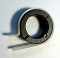
split toroid

Toroidal transformer


Ferrite toroidal cores usually form a closed magnetic circuit without any air gaps. The windings are usually wound directly onto the toroidal core using special winding machines without a coil carrier . The geometry of the toroidal core creates a circular magnetic field within the core, so practically the entire field is confined to the core material. This means that not only can high-efficiency transformers be produced with toroidal cores, but the electromagnetic interference that is emitted by the coils can also be reduced.
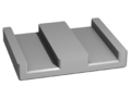
C, U, UI, E, ER, EFD ferrite cores

C core
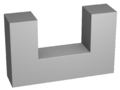
U core

UI core

E core

ER, ETD core

EFD core


"I-core" : An I-core is a rod with a rectangular cross-section that can form a closed magnetic circuit with a C or U core.
"C-" or "U-core" : C- and U-cores can either be joined with an I-core or with another core of the same type in order to form a magnetically closed circuit. The advantage of these designs is that the coils can be wound onto the coil body beforehand and then pushed over the legs. Air gaps are created using intermediate layers.
"E-core" An E-core with an I-core or two E-cores joined together form a magnetic circuit for transformers or transmitters. The coil carrier with the coils sits on the middle leg. An air gap is achieved by making the middle limb a little shorter than the two outer limbs or by joining flat partners with an intermediate layer.
Assembly example
The assembly of an ER ferrite core takes place with the help of the coil former and two metal clamps that are snapped onto the outside of the coil and that press the core halves together in the middle.
ER, ETD core

Cores and coil before assembly

the assembled inductance, here a transformer


Ferrite pot and shell cores, accessories

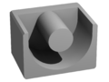
Pot cores
EP core
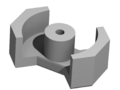
RM core

Adjustment screw cores

Pot core transformer


Two pot core halves joined together, enclose an inner coil and not only form a closed magnetic circuit, but also good magnetic shielding. This reduces EMC problems. If pot cores are used for coils in resonant circuits, the middle hole is often provided with a thread into which ferrite screw cores can be screwed for adjustment. With EP and RM pot cores, the shielding is slightly less, but they have more accessible windings and therefore better heat dissipation.
Ferrite planar cores
Planar core

Cores and coil before assembly

assembled inductance


Planar ferrite E-cores or ferrite planar cores have been developed because of the better heat dissipation, the low design and the possibility of integration in circuit board openings ( planar transformers ). The windings can be designed as conductor tracks on printed circuit boards; in the case of multilayer printed circuit boards, several turns can also lie on top of one another. This design is suitable for the industrial mass production of inductors.
Other designs
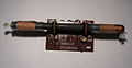
Ferrite rod cores

Ferrite rod cores
Ferrite antenna for long and medium wave
.jpg)

Ferrite rod cores bundle e.g. as the magnetic core of a magnetic antenna or ferrite antenna, the magnetic component of the electromagnetic field for receiving electromagnetic waves. Wrapped with one or more coils, these form oscillating circuits with parallel- connected rotary capacitors or a varicap diode , which are brought into resonance with the transmitter frequency when tuning. Ferrite antennas are suitable for receiving long , long ; Medium wave or short wave .
Due to the open magnetic circuit, rod cores are used to manufacture sensor coils for line detectors or inductive proximity switches, metal detectors and hearing aid receivers (induction loops).
Rod cores are still used for the production of rod core chokes. The mostly single-layer wound rod core chokes are characterized by a broadband filter effect (low capacity between beginning and end), high possible direct current bias, good heat dissipation and simple manufacture.
Ferrite perforated cores
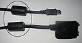
Ferrite cores as standing wave filters
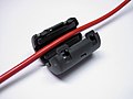
Split ferrite tube core, so-called hinged ferrite

Rod core choke with split windings, ferrite bead, damping beads
Ferrite perforated core for baluns

Ferrite perforated core as adjustable inductance


Electronic devices can cause high frequency electromagnetic interference that propagates on connected cables. In order to attenuate this interference to a legally permitted level, the cables are sometimes led through a sheath wave filter, a ferrite perforated core. Due to its inductance, this core acts like a choke and dampens high-frequency common-mode interference.
Ferrite perforated cores on individual lines can also be used to suppress interference; such threaded-on damping beads or sleeves can also dampen push-pull interference, but must be adapted to the transmission bandwidth.
Ferrite perforated cores in baluns serve as impedance converters for converting between a symmetrical and an asymmetrical line.
In high-frequency coils, for example in band filters , ferrite cores are used to adjust or adjust the inductance. For this purpose, they are provided with threads so that they can be moved with a tool inside the bobbin.
See also
literature
- Günter Springer: Expertise in electrical engineering. 18th edition, Verlag Europa-Lehrmittel, Wuppertal, 1989, ISBN 3-8085-3018-9 .
- Hans Fischer: Materials in electrical engineering. 2nd edition, Carl Hanser Verlag, Munich Vienna, 1982 ISBN 3-446-13553-7 .
- O. Zinke, H. Seither, resistors, capacitors, coils and their materials , Springer-Verlag 1982, ISBN 978-3-540-11334-8 , DOI 10.1007 / 978-3-642-50981-0
- Trilogy of inductive components: Application manual for EMC filters, switching regulators and HF circuits. Swiridoff Verlag, ISBN 978-3-89929-151-3 .
- Wolfgang Bieneck: Elektro T. Fundamentals of electrical engineering . 5th edition, Holland + Josenhans Verlag, Stuttgart 2005, ISBN 3-7782-4900-2
- Gert Hagmann: Fundamentals of electrical engineering. 6th edition, AULA-Verlag GmbH, Wiesbaden 1997, ISBN 3-89104-614-6
- Richard Boll: Soft Magnetic Materials - Introduction to Magnetism. 4th edition. Hanau 1990, ISBN 3-8009-1546-4 , p. 177; 278-279.
- C. Heck, Magnetic Materials and Their Applications, Elsevier, October 22, 2013, ISBN 1-4831-0317-X , 9781483103174
- Gregor D. Häberle, Heinz O. Häberle: Transformers and electrical machines in power engineering systems . 2nd Edition. Verlag - Europa - Lehrmittel, Haan-Gruiten 1990, ISBN 3-8085-5002-3 .
- Karl-Heinz Dietsche, Thomas Jäger: Robert Bosch GmbH: Kraftfahrtechnisches Taschenbuch . 25th edition. Friedr. Vieweg & Sohn Verlag, Wiesbaden 2003, ISBN 3-528-23876-3 .
Individual evidence
- ^ Franz Moeller, Paul Vaske (Ed.): Electrical machines and converters. Part 1 structure, mode of operation and operating behavior, 11th revised edition, BG Teubner, Stuttgart 1970.
- ↑ a b Soft magnetic cobalt-iron alloys. (PDF) VAC
- ↑ a b H. Völz: Lecture Material Magnetism. (PDF) April 1, 2010
- ↑ Tridelta, definitions and explanations (PDF)
- ↑ DIN 50460: 1988-08, Determination of the magnetic properties of soft magnetic materials; General, terms, basics of the test procedures
- ↑ TDK, Ferrite, Summary. (PDF)
- ↑ a b c d Neosid, Part 1, Introduction, General. ( Page no longer available , search in web archives ) Info: The link was automatically marked as defective. Please check the link according to the instructions and then remove this notice. (PDF)
- ^ Bosch (Ed.): Technical instruction in electrical engineering . 1st edition, Robert Bosch GmbH, Stuttgart 1976, VDT-UBE 002/1.
- ^ A. Senner: Electrical engineering . 4th edition. Verlag Europa-Lehrmittel, 1965.
- ↑ G. Herzer: Amorphous and Nanocrystalline Soft Magnets . (PDF) Vacuum melt
- ↑ Sekels, FAQ on magnetic shielding sekels.de
- ↑ Sekels, Magnetic final glow sekels.de
- ↑ a b D. Berndt, calculation of a magnetic circuit using the example of a ferrite core EF16 dietmarberndt.com
- ↑ a b G. Schindler: Magnetic components and assemblies, fundamentals, areas of application, backgrounds and history. (PDF) attempo
- ↑ O. Zinke, H. Seither, resistors, capacitors, coils and their materials, Springer-Verlag 1982, ISBN 978-3-540-11334-8 , DOI 10.1007 / 978-3-642-50981-0 springer.com
- ↑ a b Amorphous cut ribbon cores. (PDF) Sekels
- ↑ Determination of the saturation behavior depending on the premagnetization, inductance measurement on power chokes, elektroniknet.de, November 5, 2008 elektroniknet.de
- ^ Günter Springer: Electrical engineering. 18th edition, Verlag Europa-Lehrmittel, Wuppertal 1989, ISBN 3-8085-3018-9 .
- ↑ W.-R. Cander: Physically based approach according to Bertotti's theory. Calculation of iron losses. (PDF) TU Braunschweig
- ↑ a b c iron losses, definitions, energie.ch, energie.ch
- ↑ a b c d Soft magnetic materials and semi-finished products. (PDF) VAC
- ^ A b c M. Dekker: Chapter 2, Magnetic Materials and Their Characteristics. (PDF) Transformer-and-Inductor-Design-Handbook, 2004
- ↑ a b c d e steel information center, leaflet 401, electrical steel and sheet metal publications / MB401 electrical steel and sheet metal.pdf PDF
- ↑ magnetec.de ( Memento of the original from April 8, 2018 in the Internet Archive ) Info: The archive link was inserted automatically and has not yet been checked. Please check the original and archive link according to the instructions and then remove this notice. nanocrystalline tape cores for 100 kHz / 0.3 T, accessed on April 7, 2018
- ^ Giorgio Bertotti: Hysteresis in Magnetism ISBN 978-0-12-093270-2
- ↑ Electronic Developer, Online calculator, calculation of inductances electronicdeveloper.de
- ↑ Development tool for determining the exact losses in ferrites
- ↑ TDK Epcos, Ferrite Magnetic Design Tool en.tdk.eu
- ↑ Fericor, (DMEGC) Magnetic Design Tool fericor.com
- ↑ Simulation of a throttle. (PDF) Strukturbildung-simulation.de
- ↑ Calculation of the winding goods. (PDF) Walter
- ^ GWC Kaye & TH Laby, Table of Physical and Chemical Constants, 14th ed, Longman
- ↑ Pure iron has a specific resistance of 10 µΩ • cm
- ^ ARMCO-Eisen, Chemie-Lexikon, chemie.de
- ↑ AKSteel ARMCO-Eisen aksteel.de
- ^ A b Rolf Fischer: Electrical machines. 12th edition, Carl Hanser Verlag, Munich and Vienna 2004, ISBN 3-446-22693-1 .
- ^ J. Adilson de Castro, MF de Campos: COBEM Brasilia 2007, Modeling Descarborization Process of Heat Treatment of Electrical Steels. ( Memento of the original from January 11, 2018 in the Internet Archive ) Info: The archive link was inserted automatically and has not yet been checked. Please check the original and archive link according to the instructions and then remove this notice. (PDF)
- ↑ Magnetic and technological properties, cold-rolled electrical sheet and strip, DIN EN 10106. (PDF) Waasner
- ↑ Gisbert Kapp: Transformers for alternating current and three-phase current. 3rd increased and improved edition, published by Julius Springer, Berlin 1907.
- ↑ Magnetic properties of electrical steel. (PDF) Gray punching unit
- ↑ General information on electrical sheets. (PDF) EMT
- ↑ Richard Boll: Soft Magnetic Materials - Introduction to Magnetism. 4th edition. Hanau 1990, ISBN 3-8009-1546-4 , p. 177; 278-279.
- ↑ Beuth-Verlag, DIN EN 10106, DIN EN 10107 beuth.de
- ↑ a b c AK Steel International, Elektroband, aksteel.de
- ↑ Stanz- und LaserTechnik Jessen GmbH, overview of electrical sheet qualities stanz-und-lasertechnik.de
- ↑ DIN EN 10106, cold-rolled, non-grain-oriented electrical sheet and strip in the final annealed state
- ↑ DIN EN 10107, grain-oriented electrical sheet and strip in the final annealed condition
- ↑ a b G. W. Elmen, HD Arnold, Permalloy, A New Magnetic Material of Very High Permeability, Bell System Tech., Volume 2, issue 3, pages 101–111, publisher: American Tel. & Tel., USA, July 1923 archive. org
- ^ History of the Atlantic Cable & Undersea Communications, 1924 New York - Azores Cable, atlantic-cable.com
- ↑ Allen Green: 150 Years Of Industry & Enterprise At Enderby's Wharf . In: History of the Atlantic Cable and Undersea Communications . FTL design. 2004.
- ↑ Information sheet on Kernbleche. (PDF) Sekels
- ↑ Vacuumschmelze, soft magnetic nickel-iron products vacuumschmelze.de
- ↑ VAC, MuMetall, data sheet, vacuumschmelze.de
- ↑ ESPI Metals, Permalloy 80 espimetals.com
- ^ Magnetic Shield Corporation. (PDF) MuMetal
- ↑ a b T. Stijntjes, B. van Loon, Scanning Our Past From The Netherlands, Early Investigations on Ferrite Magnetic Materials by JL Snoek and Colleagues of the Philips Research Laboratories Eindhoven, Proceedings of the IEEE, Vol.96, No.5, May2008 ieeexplore.ieee.org
- ^ Soft magnetic cobalt-iron alloys. (PDF) VAC
- ↑ Magnetic properties of rapidly quenched alperm ribbons . In: science direct . September. doi : 10.1016 / 0304-8853 (84) 90161-6 .
- ^ H. Saito: Effect of Aging on the Maximum Permeability in Quenched Fe-Al Alloys (Alperm). (PDF)
- ↑ EP Wohlfarth: Handbook of Ferromagnetic Materials, Volume 5 . 1990, ISBN 978-0-444-87477-1 , pp. 1-590.
- ↑ a b G. Herzer: Amorphous and nanocrystalline soft magnets. In: George C. Hadjipanayis (Ed.): Proceedings of the NATO Advanced Study Institute on Magnetic Hysteresis in Novel Materials, Mykonos, Greece, 1-12 July 1996. Volume 338. Kluwer Academic Publishers, Dordrecht / Boston / London 1997, ISBN 0-7923-4604-1 , pp. 711–730, vacuumschmelze.com (PDF)
- ↑ Nanocrystalline soft magnetic material FINEMET. (PDF) Hitachi
- ↑ S. Graubner: Nano-crystalline and amorphous cores. (PDF) SEKELS GmbH
- ^ R. Wengerter: Nanocrystalline soft magnetic cores - an interesting alternative not only for highly demanding applications. (PDF) Sekels GmbH
- ↑ a b High Performance Nanocrystalline Foils. (PDF) Metglas
- ^ J. Petro: Advanced Materials for Motor Laminations: Past, Present and Future. (PDF) Metglas
- ↑ Hitachi, Amorphous & Nanocrystalline, hitachimetals.com
- ↑ a b c Magnetic alloys. (PDF) Hitachi Metals, Metglas
- ↑ Vitrovac VAC
- ↑ Finemet. (PDF) Hitachi Metals, Metglas
- ↑ Soft magnetic high-tech material Nanoperm. (PDF) Magnetec
- ↑ VAC, nanocrystalline soft magnetic alloys, Vitroperm vacuumschmelze.de
- ^ A b V. R. Ramanan, M. Carlen: Distribution goes green. ( Page no longer available , search in web archives ) Info: The link was automatically marked as defective. Please check the link according to the instructions and then remove this notice. (PDF) FIG
- ↑ a b c J. Beichler: Design advantages through nanocrystalline cores. (PDF) VAC
- ^ J. Petro: Advanced Materials for Motor Laminations: Past, Present and Future. (PDF) Metglas
- ↑ a b c d e f g Soft Ferrites and Accessories, Data Handbook 2013. (PDF) Ferroxcube
- ↑ a b c d Jim Cox: Iron Powder Core Selection For RF Power Applications. ( Memento of the original from December 15, 2017 in the Internet Archive ) Info: The archive link was inserted automatically and has not yet been checked. Please check the original and archive link according to the instructions and then remove this notice. (PDF) Micrometals
- ↑ a b c d CWS, How to choose Iron Powder, Sendust, Koolmu, High Flux and MPP Cores as output inductor and chokes coilws.com
- ↑ a b CSC Magnetic Powder Cores Catalog. (PDF)
- ↑ a b c Samwha: Magnetic power cores. (PDF)
- ↑ a b c d Magnetics, Magnetics Powder Cores mag-inc.com
- ↑ a b WORLD WIDE FERRITE MANUFACTURERS, Compilation by Walter - PE1ABR people.zeelandnet.nl
- ↑ SMP SINTERMETALLE PROMETHEUS GmbH & Co KG
- ↑ Spectrum, Lexicon Chemistry, Carbonyleisen Spektrum.de
- ↑ Carbonyl iron powder. (PDF) BASF
- ↑ a b c Magnetic Powder Cores. (PDF) KDM
- ↑ Micrometals, Material Characteristics, Resonant circuits and broadband frequency range micrometals.com ( Memento of the original from January 4, 2018 in the Internet Archive ) Info: The archive link was automatically inserted and has not yet been checked. Please check the original and archive link according to the instructions and then remove this notice.
- ↑ a b c XFlux Powder Cores (PDF) Magnetics
- ↑ Mega Flux. Soft Magnetic Powder Core, Presentation, 09/2011. (PDF) CSC, Chang Sung Corp.
- ^ Magnetics, Learn More about Kool Mu Cores mag-inc.com
- ↑ Powder Cores, Material Introduction & Overview. (PDF) Micrometals
- ↑ Johan child Mark, Fredrik Rosén: Powder material for Inductor cores, evaluation of MPP, Sendust and high flux core characteristics . Department of Energy and Environment, Division of Electric Power Engineering, Chalmers University Of Technology. 2013. Retrieved June 5, 2017.
- ^ A b Uni-Freiburg, Lecture Metals ruby.chemie.uni-freiburg.de
- ↑ a b c d e Learn More about Ferrite Cores. (PDF) Magnetics
- ↑ Ekbert Hering, Karl-Heinz Modler (ed.): Basic knowledge of the engineer . Fachbuchverlag Leipzig, Munich 2007, ISBN 978-3-446-22814-6 .
- ↑ a b Murata, Ferrites, murata.com
- ^ Ferrites, Impedance versus frequency. (PDF) Megatron
- ↑ Ferroxcube, Megatron, ferrite cores overview megatron.ch
- ↑ Tridelta, overview of ferrite core designs tridelta- Weichferrite.de
- ↑ Magnetics, Learn More about Ferrite Shapes mag-inc.com
- ↑ ChenYang Technologies, ferrite cores / components, soft ferrites and ferrite materials softferrite.de