
SŽD series ЭР2
|
|
This article was due to acute substance or form defects on the quality assurance side of the portal train entered.
Please help fix the shortcomings in this article and please join the discussion . Articles that are not significantly improved can be deleted. |
| SŽD series ЭР2 (ER2) | |
|---|---|
 ER 2-556
|
|
| Number: | 850 units (without number of modifications) about 9211 cars |
| Manufacturer: |
Rīgas Vagonbūves Rūpnīca Riga Electrical Machine Plant Tver Wagon Factory |
| Year of construction (s): | 1962-1984 |
| Gauge : | 1520 mm |
| Length over coupling: | 19th 600 mm (single wagon) |
| Height: | 4268 mm (box) 5086 mm (with lowered pantograph) |
| Width: | 3480 mm |
| Empty mass: | 442.4 t (ten car unit) |
| Service mass: | 60 t (railcar) |
| Wheel set mass : | 17 t |
| Top speed: | 130 km / h |
| Continuous output : | 4000 kW (ten car unit) |
| Starting tractive effort: | 263.5 kN |
| Acceleration: | 0.6 m / s² |
| Braking delay: | 0.8 m / s² |
| Driving wheel diameter: | 1050 mm |
| Power system : | 3 kV = |
| Power transmission: | Overhead line |
| Number of traction motors: | 4 (motor vehicle) |
| Seats: | about 1050 (ten car unit) |
The ЭР2 (ER2) are multiple units built at the Rigaer Waggonfabrik (RVR) in Latvia , which are used specifically in suburban traffic. They were on the state railways of the former Soviet Union and are still in use in many CIS countries today . The construction of the units can be described as the modernized version of the SŽD series ЭР1 . The vehicles differed from this series by their combined entrances and improved electrical equipment.
Predecessor vehicles

The use of electric multiple units in the former Soviet Union began on July 6, 1926 in the Baku - Sabunçu section of the railways around Baku . Each multiple unit consisted of a multiple unit and one or two sidecars. All the axles of the railcars were powered, one railcar had an output power of 300 kW (4 × 75 kW) at a contact wire voltage of 1200 V = . These vehicles were retired in the 1940s.
On August 3, 1929, the connection of suburban trains in the Moscow - Mytishchi section was opened. Three -part electric multiple units of the С series were operated on this section . Each unit consisted of a railcar with an output power of 600 kW (with the following modifications 720 kW) and two sidecars. The vehicles for a contact wire voltage of 1500 V were manufactured in the Mytishchi wagon factory . The electrical equipment originally came from Metropolitan-Vickers , soon afterwards the delivery to the Moscow electrical machine factory Dynamo began . From the second half of the 1940s, the cars were manufactured in the Rīgas Vagonbūves Rūpnīca , the electrical equipment was supplied by the Riga electrical machine plant . The vehicles were delivered up to 1958 in various modifications for different contact wire voltages; series С в (S w ) and С д (S d ) for 1,5 kV; the С м (S m ) and С р (S r ) for 1,5 and 3 kV; the С м в (S m w ) and РС (RS) (with electric brake), the С р 3 (S r 3 ) and С м 3 (S m 3 ) for 3 kV DC voltage . The names of the vehicles have been given here with Latin letters. The main shortcoming of all versions was the bearing of the traction motors in a pawl-bearing design , which reduced the speed of the vehicles to 85 km / h limited.
In 1954 the Rīgas Vagonbūves Rūpnīca delivered a three-part test version , which was given the designation СН . The vehicles had modified traction motor mountings. This led to an increase in design speed to 130 km / h. In the mid-1950s, there was a great need for high-performance, high-speed vehicles for suburban lines that could not be met with the existing multiple units. Therefore, in 1957, in cooperation with the Rīgas Vagonbūves Rūpnīca and the Moscow electrical machine factory Dynamo, initially five multiple units were delivered, which were given the series designation ЭР1. Like the units of the later series ЭР2, they consisted of five groups of two cars that belonged together. This made the units significantly longer than their predecessors. For the first time, the entrance doors were opened and closed centrally by the driver. Compared to the previous types, the car bodies were around 10 % lighter, they ran on coil-sprung bogies. These vehicles significantly reduced the operating time in some sections of the Moscow and Leningrad railway nodes, but they were only suitable for high platforms .
Design and construction of electric trains ЭР2

On many railway lines in the former USSR , the technically and morally outdated electric multiple units had to be replaced by faster and more powerful vehicles. At the same time, the new vehicles should have a larger capacity and be suitable for use on lines with low-height platforms. That is why the Rīgas Vagonbūves Rūpnīca developed a modernized version of the ЭР1 series. The solution for the different platform heights was seen in the use of combined exits. The designation ЭР2 was intended for the new vehicles . The car bodies were reinforced, including the floor, side walls, end walls and head pieces as well as door cutouts. When designing the vehicles, great importance was attached to standardization with the ЭР9 , which was developed at the same time . One consequence was the relocation of the complete mechanical braking system to the bogies. Instead of one central brake cylinder per car, there were two per bogie.
Instead of the lead-acid batteries that were common up to now, the cars were fitted with alkaline-cell batteries , and newly developed generators were also installed. The alkaline batteries were already installed in the ЭР1 126-128 in the 1960s, the generators had already been used in the ЭР1 183 and 225-232. The new multiple units were given the factory designation 62-61 . Motor cars were designated 62-62 , control cars 62-63 and intermediate trailer cars 62-64 .

In 1962 the Rīgas Vagonbūves Rūpnīca and the Tver wagon factory delivered the last multiple units of the series ЭР1 (No. 218-259). From this year the production of 48 electric multiple units of the series ЭР2 (inventory numbers 300 - 347) began. As with the ЭР1, the Rīgas Vagonbūves Rūpnīca produced the boxes and the motor bogies, the Tver wagon factory the boxes for the control and intermediate trailer cars and the running bogies. The Rigaer Elektromaschinenwerke supplied the electrical equipment and the traction motors. The final assembly took place at RVR. In 1968 the Twer wagon factory ended the production of the car bodies and only supplied running bogies.
There was no uniform numbering within production, as the vehicles were delivered in sections. The units had different numbers of sections depending on the area of application and purpose. Normally the motor cars were marked with even numbers (02, 04, 06 etc.) the control cars were marked 01 and 09, and the intermediate cars had the remaining numbers with odd numbers in the unit. There were four-digit and five-digit numbers.
In 1974 the shape of the driver's cab was changed. Instead of the previous round front, the control cars were given straight, angular driver's cabs. The first unit equipped with it was number 1028.

In September 1984 the Rīgas Vagonbūves Rūpnīca delivered the last multiple unit with the number 1348. A total of 850 trains were delivered, of which 629 with ten, 134 with twelve, 75 with eight, 7 with six and 5 with four cars. In addition, numerous individual cars were built as control, motor and intermediate trailer cars. That made a total of 4511 sections and 189 additional cars. The manufacturer then delivered ЭР2P and later ЭР2T. Both types received a resistance brake . The table shows the production of the delivered vehicles broken down by unit number and additional wagons produced.
| Construction year | Number of multiple units delivered | Multiple unit numbers | Cars per multiple unit | Number of additional control cars | Number of additional intermediate cars | Number of additional head sections | Number of additional intermediate sections |
|---|---|---|---|---|---|---|---|
| 1962 | 482 | 300-347 | 10 | - | - | - | - |
| 1963 | 799 | 348-427 | 10 | - | - | - | - |
| 1964 | 744 | 428-501 | 10 | 80101; 80107; 80201; 80207 | - | - | - |
| 1965 | 704 | 502-571 | 10 | 80301; 80307; 80401; 80407; 80501; 80507 | - | - | - |
| 1966 | 650 | 572-634 | 10 | 80601; 80607; 80701; 80707; 80801; 80807; 80901; 80907; 81001; 81007; 81101 | - | - | - |
| 1967 | 251 | 635 | 10 | 81201; 813-844 | 701-732 | - | - |
| 636-658 | 8th | ||||||
| 1968 | 40 | - | - | 845-864 | 733-752 | - | - |
| 1969 | 128 | 659-674 | 8th | 865-872 | - | - | - |
| 1970 | 382 | 675-700; 900-902 | 8th | 873-884 | - | - | - |
| 903-910; 913; 914 | 10 | ||||||
| 911; 912; 915 | 4th | ||||||
| 916-918 | 6th | ||||||
| 1971 | 344 | 919-950; 952 | 10 | - | - | - | (67907 + 67908); (68007 + 68008); (69507 + 69508) |
| 951 | 8th | ||||||
| 1972 | 332 | 953-963; 966-971; 973-975; 977-981 | 10 | - | - | - | 2000-2028 |
| 964; 965 | 8th | ||||||
| 972; 976 | 4th | ||||||
| 1973 | 378 | 982-987; 992-1014 | 10 | - | - | 3000-3005 | 2029-2050 |
| 988-991 | 8th | ||||||
| 1974 | 342 | 1015-1037; 1039-1041; 1043-1045 | 10 | - | - | 3006-3009 | 2051-2067 |
| 1038; 1042 | 6th | ||||||
| 1975 | 376 | 1046-1079 | 10 | - | - | 3010-3015 | 2068-2078 |
| 1976 | ... | 1080-11111 | 10 | - | - | 3016-3021 | 2079 |
| 1977 | ... | 1112-1128; 1131; 1140-1145 | 10 | - | - | 3022-3029 | 2080-2085 |
| 1129; 1130; 1132-1139 | 12 | ||||||
| 1978 | ... | 1149-1155; 1159-1163; 1166; 1167; 1170; 1171; 1174-1179 | 10 | - | - | 3030 | 2086-2100 |
| 1146-1148; 1156-1158; 1164; 1165; 1168; 1169; 1172; 1173 | 12 | ||||||
| 1979 | ... | 1182; 1183; 1186; 1187; 1190; 1191 | 10 | - | - | 3032 | 2101-2108 |
| 1180; 1181; 1184; 1185; 1188; 1189; 1192-1210 | 12 | ||||||
| 1980 | ... | 1244; 1245 | 10 | - | - | - | 2109-2150 |
| 1211-1243 | 12 | ||||||
| 1981 | ... | 1250-1253; 1270-1272 | 10 | 8001-8009 | - | 3031; 3033; 3034 | 2151-2164 |
| 1246-1249; 1254-1269 | 12 | ||||||
| 1982 | ... | 1278-1280; 1283; 1284; 1287-1294; 1296-1300 | 10 | 8010-8038 | - | - | 2165-2167 |
| 1273-1277; 1281; 1282; 1285; 1286; 1295 | 12 | ||||||
| 1983 | ... | 1302; 1303; 1305-1307; 1309-1311; 1314; 1315; 1317-1319; 1325 | 10 | 8039; 8040 | - | 3035-3041 | 2168; 2169 |
| 1301; 1304; 1308; 1312; 1313; 1316; 1320; 1322-1324 | 12 | ||||||
| 1321 | 6th | ||||||
| 1984 | ... | 1331; 1335; 1340-1342; 1346-1348 | 10 | - | - | 3042-3057 | - |
| 1326-1330; 1332-1334; 1336-1339; 1343; 1344 | 12 | ||||||
| 1345 | 6th |
construction
The basic concept corresponds to the SŽD series ЭР1. The main difference is the shape of the entrances. The ЭР1 are only intended for high platforms, while the ЭР2 are suitable for operating high and low platforms. The vehicles differed in some details of the electrical equipment (generator, battery). The ЭР2 railcars lacked the brake slack adjuster, which could readjust the brake cylinder stroke when the brake pads were worn.
Entire scheme
A multiple unit of the series ER2 is made up of sections, these consist of a motor car and a trailer or control car. A section with a control car with a driver's cab is a control section , with a sidecar an intermediate section . The smallest, operationally usable unit consists of two control sections and thus four cars, the longest two control sections and four intermediate sections (twelve cars), the majority of the trains ran with ten cars. Operation with trains of more than twelve cars was not recommended because the generator for the power supply of the entire unit was overloaded.
The carriages of the unit were connected to each other with the central buffer coupling. This coupling option allows the individual wagons to be connected and disconnected quickly, and a difference in height of ± 100 mm due to track position errors can be compensated for. The electrical equipment of the vehicles is housed outside the passenger compartment on the roof (pantograph) or under the car (compressor, resistors). The equipment under the car is housed in lockable and removable equipment boxes. The equipment placed on the roof is also distributed in cupboards and thus protected from dust, moisture and snow. Some of the high-voltage parts (e.g. the energy consumption meters) are housed in cabinets in an entry room. The equipment that was intended for the management of the electric train was also housed in the vestibules of the cars. These administrative parts were placed in the driver's cab of the machinist in the control car.
In the course of the long delivery time there were a number of design and design changes. The most striking example are the angular driver's cabs from multiple unit 1028 onwards. Further changes were made as part of the maintenance in the repair shops.
Interior decoration
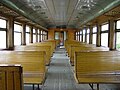
Original version with slatted seats

partially modernized

modernized with lightly padded seats


The entry areas are at the ends of the car. The entrance doors are double-leaf pocket sliding doors. In the original state, the entrances for changing passengers on low-lying platforms were equipped with step boxes with four steps. The passenger compartment takes up the largest area of the interior of the car. The main area is taken up by the seats; luggage racks are attached lengthways over the windows. The usual coat hooks for outer clothing are between the windows. The seat divider is usually 3 + 3, there is a continuous central aisle. The number of seats per car was changed several times during the year of construction. In some cases, seats were omitted in order to achieve more standing space and thus a higher total capacity. In the intermediate car the number of seats is 107 to 110, in the control car 77 to 88. A ten-car train can have up to 1050 seats, the total capacity of such a train is 1600 passengers. The entry areas are separated from the passenger area by double sliding doors.
The lighting, heating and ventilation system ensures that pleasant living conditions in the passenger compartments are maintained under Russian climatic conditions with large temperature differences. Due to the long procurement and operating time, the lighting changed several times. Originally it consisted of 20 lights with incandescent lamps in the middle car, which were attached to the ceiling. There were 16 lights in the smaller passenger compartments of the control car, and two in the entry areas. The lighting is fed by the generator unit with a voltage of 50 V. If the contact line voltage or the on-board power supply fails, the lighting fails. In this case, emergency lighting is available, which consists of a few lamps from the main lighting and is fed by the vehicle battery. The passenger compartment was ventilated with the help of two double-row fans. These are housed in the vestibules and expel the fresh air in the passenger compartment through openings above the vestibule doors. The fresh air is sucked in through air inlets above the entrance doors and then runs through a network filter to the fans. In the warm season, the fresh air is generally drawn in from the outside, in winter partly from the outside and from inside the vehicle. The passenger compartments are heated by radiators under the seats, 20 in the central car and 14 in the control car. The output of a radiator is 1 kW with a supply voltage of 750 V. That is why they were housed in housings that were specially earthed.
Mechanical equipment
box
As in the ЭР1 series, the car bodies are self-supporting welded steel constructions. The box frame consists of rolled profiles, the outer wall sheets with a thickness of 1.5 to 2.5 mm are corrugated to increase the rigidity . To accommodate the SA-3 central buffer coupling and its pulling and pushing device, a shortened buffer plank is located at the ends of the boxes. Due to the use of aluminum for the entrance doors and channels, the weight of a car is only slightly higher than that of the ЭР1 (the weight of an intermediate car of the betrugР1 was 35.4 t, for the ЭР2 38.3 t). The double-leaf entrance doors are opened and closed pneumatically. They are provided with recessed grips for manual emergency opening. On the end walls of the cars (except on the driver's cab side of the control car) there was the possibility of changing from car to car.
Bogies

Each car runs on two two-axle bogies, they are sprung in two stages. Running bogies and motor bogies have a number of design differences.
The bogies of the motor vehicles included the long and cross members as well as the mounts for the pairs of wheels relative to the frame. The longitudinal members of the frame had a reinforcement in the form of a support in the middle part. This meant that the weight of the car body could be absorbed at this point on the side members via a spring beam and two suspensions. The crossbeams had a composite shape, which means that they were used to mount the supporting frame suspension of the traction motors. The frame of the bogies supported the pairs of wheels on bushes using so-called bush-spring suspensions made from coil springs. On the frame of the bogie, the upper spring beam, on which the weight of the wagon was transferred directly, was supported via central spring suspensions and double suspension. Pendulum suspensions transferred the load from these to the bogie frames. In the spring suspension of the first trains, leaf springs were still used, from 1965 they were changed to coil springs, which increased the deflection of the spring system from 95 to 120 mm. To dampen the vibrations, dampers were installed (friction dampers were used in bearing level 2, hydraulic dampers in the central damping system). The box of the car was supported on sliding surface supports. The sliding version was made of plastic and increased the smoothness of the vehicles. The pivot was used to transmit the driving and braking forces. This also served in part to transfer the weight of the car body.
The construction of the bogies of the sidecars was similar to that of the passenger coaches, only they had a shorter frame. The spring suspension was designed to be softer (with more deflection). The pivot consisted of three parts. The bushing suspension dampers were on the inside (not outside, as with the motor vehicles). At the first bogie of the control car there was a console for accommodating the roles of the locomotive signaling. In earlier ЭР2s, as with the ЭР1, bogies of the type КВЗ-5 / Э ( KWS-5 / E ) were used for the sidecars (produced by the Tver wagon factory), from the railcars from inventory number 544 those of the type КВЗ-ЦНИИ / Э ( KWS-ZNII / E ). The KWS-ZNII / E bogies had the following differences from the KWS-5 / E bogies : the suspension was softer, the spring bearing was fixed in relation to the frame; the weight of the trolley was only transferred to the spring mounting via sliding plates on the side, with the KWS-5 / E additionally via a central support.
Traction transmission
The motor axles of the electric train had an individual drive, that is, each motor axle was driven by its traction motor. The torque was transmitted from the electric motor via a reduction gear to the drive axle with a straight-toothed spur gear ratio; the transmission ratio was 73:23. The reduction gear was embedded in a steel body. The large wheel with a module of 10 sat directly above the drive axle, the smaller wheel was shrunk onto the shaft of the electric motor. The housing of the reduction gear was supported from one side on the drive axle and the other side attached to the cross member of the bogie. Originally the suspension of the reduction gear on the bogie frame consisted of sickle-shaped brackets with rubber-metal dampers, later vertical rods with four dampers were used. A special coupling was installed between the large wheel of the gearbox and the drive wheel of the bogie. A cam coupling was used in the first multiple units, later an elastic coupling made of rubber elements was used.
Wheelsets
The driving wheel sets have tires, their running circle diameter when new is 1050 and the tire thickness is 75 mm. The wheel tires are shrunk onto the wheel centers, which are spoked wheels. In this form, the wheel spiders were pressed onto the axles, with a wheel spider having widespread hubs for power transmission through the large gear of the reduction gear.
In contrast to the driving wheel sets, the running wheel sets have monobloc wheels with a running circle diameter of 950 mm.
Electrical equipment

The electrical scheme of the multiple units of the series ЭР2 was based on that of the SŽD series ЭР1. Each motor vehicle had four traction motors that were arranged in pairs in a row for each bogie. The regulation of the voltage in the control of the traction motors was carried out with classical resistance control with simultaneous change of series connection or parallel connection and change of their magnetic poles. To protect the traction motors from overexertion and power surges, a number of protective devices were installed on the electric train; a quick breakdown switch, overvoltage relay , differential relay and much more. In the past, fuses were used in the first electric trains to protect the chain of the traction motors, from the vehicles with the inventory number 539 onwards, in connection with the increased reliability of the protective devices, these were no longer used.
Description of the work of the force scheme

The electric train had 18 start-up levels. The acceleration was achieved with the help of resistors that were switched or switched off with special contactors depending on the level . These contactors had the designation 1 to 12 in the scheme and were combined in a group of switches, which was called силовы контро́ллер ( power switch ). The machinist managed the electric train with the help of his drive switch. The management system was indirect, that is, the machinist set a certain position on the drive switch, the management system set the power switch to the appropriate position. If the train only had to be driven at low speed (e.g. when maneuvering), the machinist only managed the handle in the first position M (shunting gear). In this position, the following contactors closed: the line contactors (1-2), bridge contactors (7-8). All traction motors were connected in series and all resistors were used in the chain (R tot = 17.66 ohms). When changing the handle on the drive switch, a gradual transition from position to position was achieved with the power switch , as a result of which the number of resistors used was constantly reduced. In contrast to electric locomotives, where the start-up position is recorded by the drive switch, in the case of the electric train, the transition from one intermediate stage to the other is automatically realized by an acceleration relay that regulates the acceleration of the electric train. In addition, the management scheme provided for manual control from position to position. When the power switch was in the 9th position , the two drive motor groups were still connected in series, but the drive motor excitation was 100%. In the 10th position the stimulation was 67% and in the 11th position 50%.

To further increase the speed, the traction motors were converted to a parallel connection . For this, the two parallel contactors ( P1 and P2 ) closed in the 12th position after the bridge contactors switched off. Up to the 16th position the number of controlled resistors was continuously reduced. In the 17th position the weakening of the magnetic poles was up to 67% and in the 18th position up to 50%. At the 18th position, the train was able to reach its maximum speed. For these 18 positions of the power switch , only speed steps 1-4 on the drive switch were operated. In the event that the power should be switched off, the handwheel of the drive switch was set to 0 . The exact representation of the contactors used is shown on the enclosed sketch.
Electric traction motors
The electric traction motors of the multiple unit had a supporting frame suspension, which provided maximum protection against impacts on uneven tracks. In the first ЭР2 the traction motors of the SŽD series ЭР1 were used, namely the ДК-106Б ( DK-106B , that means traction motors from Moscow Electromechanical Factory Dynamo , 106th series, B version of the design). These electric traction motors were connected in series for direct current with excitation and had four main and four secondary poles. The working voltage of a drive motor was 1,500 V, the insulation was calculated to be 3,000 V. In contrast to the traction motors of the electric locomotives , the nominal value regime worked when the magnetic field was weakened, and the full excitation was only used when starting. The drive motor was ventilated by its own ventilation (the fan was attached to the shaft of the electric drive motor), the air was extracted from the same ventilation openings as from the ventilation, above the entrance doors.

At the beginning of the 1960s, the method for calculating the traction motors was changed, which led to the simplification of the planning of the electric traction drive motors. In connection with this, a new type of electric drive motor was created at the Riga electrical machine works, which was given the designation УРТ-110А ( URT-110A , which means unified Riga traction drive motor). It had a similar characteristic to that of the ДК-106Б . The traction electric drive motors УРТ-110А were used in the ЭР2 from March 1964 by the railcar, starting with the number 446. In 1970 the factory changed to the production of the УРТ-110Б , which differed from the УРТ-110А by the shape of the collector . The electric traction motors of the new type were used from January 1971 onwards from the railcars with the inventory number 919. The main characteristics of the electric traction motors ДК-106Б and УРТ-110 are listed in the table (in the numerator for the stated data values at 100% excitation, im Denominator values at 50% excitation).
| Designation drive motor | Leistung, kW |
Strom, A |
Ankerdrehzahl, 1/min |
maximale |
Masse, kg
|
|||
|---|---|---|---|---|---|---|---|---|
| Hourly regime | Permanent regime | Hourly regime | Permanent regime | Hourly regime | Permanent regime | |||
| ДК-106 | 187/200 | 145/160 | 136/146 | 105/115 | 830/1140 | 945/1320 | 2080 | 2200 |
| УРТ-110 | 178/200 | 137/158 | 132/146 | 100/115 | 850/1145 | 952/1315 | 2080 | 2150 |
High voltage equipment
Scissor pantographs were responsible for the transmission of electrical energy from the contact wire to the equipment of the electric train . These had a pneumatic drive which ensured that if the air pressure in the main air tank line fell below a certain level, the connection would be interrupted. Springs were used to lower the pantograph. A pantograph was installed on each motor vehicle so that the motor vehicle had to be transferred to the depot in the event of damage. It was not possible to switch off a group of traction motors in the event of a defect; in the event of a defect in one traction motor, the entire motor vehicle in the unit had to move along without power.
Equipment protection
The protection of the electric traction motors against short circuits was carried out with the help of high-speed switches, which could switch off the traction motors with a current in the traction motors of more than 575 A in a time of 0.002 - 0.005 s. An earthing protection relay with the designation ДР ( DR ) compared the current at the beginning and at the end of the power chain, and even with a small difference of about 40 A it ensured that the quick- release switch with the designation БВ ( GW ) closed. A relay with the designation РБ ( RB ) served as anti- skid protection or anti-slip protection . It opened if the speed of one of the traction drive motors was already slightly different from that of the others. Mechanical locking of the wheels prevented a coupling between the traction drive motor and the transmission. A relay overload with the designation РП ( RP ) opened when the current in the chain of the traction drive motors was exceeded greater than 265 A. If one of the last two relays was opened, the acceleration of the train was automatically reduced. In addition, an optical signal appeared in the operator's desk. When the relay with the designation РБ was pulled , an acoustic warning signal appeared.
To protect the locomotive brigade from electric shocks, all cabinets and boxes had a special electromechanical lock. This prevented the cabinets from opening when the pantographs were in place. The other way around, the pantograph could not be lifted if one of these cabinets and boxes was open. From the ЭР2-544 on, a relay was introduced to block the roof ascent with the designation РБЛ ( RBL ). This relay blocked the removal of the roof riser when the pantograph was on. All automatic doors had automatic transmitters from the start, thanks to which the machinist could see that all automatic doors were closed.
There was also a voltage test relay with the designation РН ( RN ), it opened if a voltage lower than 2400 V was measured in the high-voltage chain, and the machinist was notified. A relay for protection against overloading of the generator and the compressor with the designation РПДиК ( RPDuK ), a relay for protection against overcharging of the heater with the designation РПО ( RPO ) and automatic switches of the management with the designation АВУ ( ABU ) completed the protective devices. If the air pressure in the main air line fell below a certain value, the management chain automatically switched off the traction drive motors, which meant that the train could not run without air pressure.
Auxiliary machines

The converter ДК-604В ( DK-604W ), which combined two machines in one body, was installed under the side and control cars of the electric train ; the dynamo and independently of it on one axis the power generator of the chain of management. The dynamo was a two-collector machine that was fed with 3 kV from the motor vehicle. The generator was fed with 1.5 kV, it served to feed the compressor. The generator was used to power the management chain, the nominal voltage of which was 50 V. The rotation of the shaft of the entire switch was 1000 / min, the dynamo had an output of 12 kW with a current of 5.3 A. The generator had an output of 10 kW with a current of 200 A. The mass of the entire switch was 1,200 kg. When the generator was inoperable, the management chain received power from the rechargeable battery that was in every car on the train. A motor compressor was housed in each sidecar, it was driven by the motor with the designation ДК-405В ( DK-405W ). This DC electric motor had an output of 5 kW. Its working current was 4.65 A at a voltage of up to 1500 V.

The fans for the ventilation of the passenger compartment were driven by type П-41 ( P-41 ) electric motors, the working voltage of which was 50 V at a rated speed of 1200 / min. The mass of an engine was 78 kg. From ЭР2-1028, when the vehicles received the machinist's new cabin, this motor was used to drive the fan for heating the cabin.
Pneumatic equipment
Compressed air was used in many systems and mechanical devices on the ЭР2 electric hoist. It was particularly used in the braking system, when actuating the brake cylinder and other braking devices on the train, as well as for opening and closing the doors. Some electrical contactors were switched (e.g. pantographs and main switch) and they were used for the sound signal operated by compressed air. The compressed air was generated in the motor compressor, which was housed under the sidecar and sometimes under the control car. The pressure in the main air tank line was 6.5 to 8 bar. An auxiliary compressor was housed in each motor vehicle. This was used to generate compressed air for lifting the pantograph when the air lines were empty. In earlier electric trains, the auxiliary compressor had the option of manual auxiliary control; later it could be operated electrically with power from the rechargeable battery.
The air-controlling actions in the power chain had two advantages: the compressed air could operate the moving parts of the contactors, which was particularly advantageous with high currents, and the compressed air control could relieve the generator's electrical circuit. In addition, it was impossible to operate the train with the brakes off and the door uncontrolled.
Braking device
An electropneumatic brake , which was designed as a two-sided block brake , was used on the ЭР2 electric train . The sidecar had a brake cylinder with a diameter of 14 "that operated all 16 brake pads (two per wheel) via a lever linkage. The motor cars had four brake cylinders, two of which were housed in the bogies. This diagram of the braking equipment was used in order to achieve maximum unification with the ЭР9 that was created at the same time . In addition, the brake equipment was simplified by the lever system. The brake was supplied from the brake highway, which was supplied from compressed air distributors (one in the sidecar and two in the motor vehicle) and the driver's brake valve . the working pressure in the brake pipe was 4.5 -. 5.5 bar in the compartments of travelers, the cabs and the anterooms were housed emergency brake.
Equipment set up during modernizations


In the second half of the 1990s, the ЭР2 was updated with various facilities and systems. They used to have a fire signaling system called ПРИЗ ( PRIS ). This system included two administrative blocks, smoke and fire alarms , housed throughout the unit, and there were also special control blocks (one per car). If one of these transmitters responded, the engineer in the driver's cab received a sound signal about fire, and the number of the car in question was also displayed. The fire signaling system was supplemented by fire fighting systems in the form of fire extinguishers . In addition, at the end of the 1990s, the train was equipped with an automatic control system called САВПЭ ( SAWPE ). This system, which works in a similar way to the CIR-ELKE system in Germany , made it possible to realize the automatic responsibility of the electric hoist with minimal involvement of the machine operator. It allowed to realize the rational management of energy while driving. It enabled various voice messages for the machinist to inform the travelers. However, the system had a number of program errors, which mainly manifested themselves in incorrect information at a greater distance. Often these systems were added РПДА ( RPDA ). This system represented a system of registration which could write down the following information on electronic cards:
- Number of train and unit,
- Movement parameters (time, speed, distance traveled)
- Display of the locomotive signaling
- Electricity of every motor vehicle (only for motor vehicles that were equipped with special current sensors)
- Response of the БВ , of electropneumatic valves (e.g. in the case of emergency braking) and also information on how many times and when the heating of a car was switched on.
- Inclusion of system САВПЭ .
Likewise, the electric train was equipped with all other equipment for operation, with a speedometer, automatic speed signaling, mainly АЛСН ( ALSN ). From the mid-2000s, this system was replaced by the КЛУБ system and at the same time by radio equipment.
Operation of the electric train ЭР2

Initially, the ЭР1 electric trains were used on the railway nodes in Moscow, Leningrad and Kiev . The first vehicles of the ЭР2 series were sent there. In contrast to the ЭР1, these vehicles were designed for high and low platforms . At the same time they were used for a number of secondary connections, where they replaced a number of older class C railcars . This brought a significant increase in the speed of travel of the trains. By the mid-1960s, the trains were already working on the following suburban connections to the cities of Irkutsk , Samara , Kurgan , Omsk , Novosibirsk , Tula , Chelyabinsk ; they ran in the Krasnodar region , the Stavropol region , as well as in Georgia , Latvia and the Ukraine . Their routes led to the Black Sea coast in Abkhazia and Adjara in the Crimea .
When the delivery of the electric trains with the changed head shape began (from inventory number 1028), the vehicles became more contemporary and were mainly used in the areas around Moscow and Leningrad. In 1980, the vehicles were used for transportation at the 1980 Summer Olympics . On January 1, 1976, there were 2929 different two-wagon sections on the railways of the SŽD , these were distributed over the following railway companies:

- the railway of the Azerbaijani Soviet Socialist Republic had twelve sections (plus four different head sections and one middle section),
- the Turkestan-Siberian Railway had 359 sections, plus twelve additional wagons as head or intermediate cars
- the railway around Nizhny Novgorod had ten sections,
- the Transcaucasian Railway had 144 sections, plus four different head sections
- the railways around Kuibyshev had 288 sections, plus three middle sections
- the railways around Lviv had twelve sections, plus two head sections
- the Moskowskaja selesnaja doroga had 803 sections, plus four different head sections, 51 different middle sections and seven pairs of cars (control and motor cars)
- the Oktoberbahn had 610 sections, plus eight different middle sections and two different wagons (control and motor vehicles)
- the Baltic railways had 189 sections, plus seven different wagons (control and motor vehicles)
- the railway around Privolschsk had 63 sections, plus four different wagons (control and motor vehicles)
- the Severo-Kawkasskaja seleznaja doroga had 32 sections
- the railway in Central Asia had 23 sections, plus two different middle sections and a few different wagons (control and motor vehicles)
- the Южная железная дорога had 257 sections
- the railway in the southern Urals had 127 sections, plus three different middle sections and six pairs of different wagons (control and motor vehicles)
For comparison, the SŽD 613 had three-part electrical sections with the designation S r 3 , 1294 two-part sections with the ЭР1 series, 1728 sections with the ЭР9 series and 268 sections with the ЭР22 series. In this context, it could be said that the ЭР2 series came to 2/5 of the entire park of Soviet electric multiple units .
But as early as the early 1970s, vehicles from the derР2 series were taken out of service. In 1984 the Rīgas Vagonbūves Rūpnīca began delivering electric multiple units for direct current with a resistance brake with the designation ЭР2P (ER2R) and later ЭР2T (ER2T). These electric trains had more powerful traction motors, and the drag brake made it possible to reduce energy consumption. They replaced the ЭР2 on many high-speed connections (e.g. Moscow - Leningrad). 1993 began the delivery of the electric multiple units 2Т2 of the Torchok wagon factory and the electric multiple units ЭД2Т at the machine factory Demichowo . The railcars of the series ЭР2 were gradually transferred to lines of secondary character or they were used by other railway companies as a replacement for the SŽD series ЭР1, or they were retired. As early as February 2007, the last railcar with a round head was retired from the Moskovskaya zhelesnaja doroga . It was the ЭР2.1017. Many control cars were used for the train called Sputnik . In 2009 the ЭР2.1028 was taken out of service on the Oktoberbahn - the first ЭР2 with a modified cabin. In 2010, the Moskovskaya zhelesnaja doroga retired the ЭР2.1212 with aluminum window frames , soft seats and rubber beads between the wagons. The electrification of railways with alternating current played a special role in the fate of the ЭР2 . So under these conditions the ЭР2 stopped working on the Turkestan-Siberian Railway , the railways around Privolschsk and the railways around Nizhny Novgorod . Only the ЭР2 were still in active operation. In many factories, the trains received some major overhauls, after which the deadline for their use was extended. In this way, the period of cars built in 1962 (e.g. ЭР2.304 and ЭР2.339) was continued. Often the cabins were swapped for these capital improvements on the multiple units and were often given new designations (ЭС2 (ES2) or ЭМ4 (EM4)). According to the document, the vehicles were listed as new vehicles. These vehicles have been used on many known connections, e.g. B. the ЭМ4 were used as Sputnik on the Moscow - Mytishchi line.
At the beginning of 2009 there were still 2834 sections of the ЭР2 on the railways of the post-Soviet area , which were distributed on the following railways:
- the railways in Abkhazia had two sections, the ЭР2.383,
- the railways in Azerbaijan had twelve sections, plus four different head and one middle section and four different wagons,
- the railways in Georgia had 130 sections, plus three different head and three different middle sections,
- the Donetska Salisnytsya had 15 sections,
- The Turkestan-Siberian Railway had 278 sections, plus two different head and four different middle sections and ten pairs of different wagons,
- the railways around Kaliningrad had 30 sections, plus three different middle sections,
- The railways around Kuibyshev had 216 sections, plus six different middle sections and six wagons,
- the railways in Latvia had 37 sections, plus two different head sections, ten different middle sections and seven wagons,
- the railways around Lviv had 76 sections, plus six different head and one middle section,
- the Moskovskaya zhelesnaja doroga had 1066 sections, plus eleven different head and 46 different middle sections,
- there were 368 sections at the Oktoberbahn , plus nine different middle sections,
- the railways in Dnepropetrovsk Oblast had 31 sections, plus a middle section and two different wagons,
- the railways around Sverdlovsk had 147 sections, plus two head, two middle sections and two wagons,
- in the northern section of the RŽD there were 16 sections, plus two different middle sections,
- The Severo-Kawkasskaya zhelesnaja doroga had 21 sections, plus three different middle sections,
- the railways in Uzbekistan had eleven sections, plus three different middle sections,
- the railways in Estonia had 20 sections,
- in the southeast part of the RŽD there were 24 sections, plus a middle section,
- At Piwdenna Salisnyzja there were 134 sections, plus five different head sections, two different middle sections and two pairs of wagons,
- the Harawkowkasjan Jerkatughi had 79 sections, plus four different head sections,
- The railways in the Southern Urals had 83 sections, plus three different middle sections and five different wagons.
For comparison, at that time there were still 2290 electric multiple units of the series ЭР9 of all versions, 1639 sections of the ЭР2P and ЭР2T, 628 sections of the ЭТ2 of all versions, 51 sections of the ЭД2 , 1237 sections of the ЭД4 and 921 sections of the ЭД9 on the railways of the former USSR counted. At that time the warenР2 were numerically the third largest row in the park of electric trains of the railways in the post-Soviet area .
Likewise, some ЭР2s were given as exhibits in railway museums. Thus, in the Railway Museum Riga a head section of the ЭР2.397, the Railway Museum of Novosibirsk there is a head section of the ЭР2.673, the Museum of the October Railway a control carriage is from the ЭР2.963, and the Railway Museum of Tashkent is one himself Electric train with control car from the ЭР2.1045 and ЭР2.1270.
Experiments with the electric train ЭР2
The relatively simple construction of the ЭР2 electric train and its mass production meant that further tests were carried out on the vehicles of this series. In the past, they all concerned the control system and especially the start-up, where a lot of energy was lost. They also concerned systems of automatic authority автомашинисты ( automaker ). In 1963 the electric hoist ЭР2.413 was delivered with this system for the first time, which was given the changed designation ЭР2 a (project designation ЭР3). It was transferred from the manufacturing plant to the Moscow-October depot. In day-to-day operations, there were many design flaws in operation, so it was removed again and the train was transferred to the Leningrad Finnish Railway Station depot in 1979 and later to the Leningrad Baltic Railway Station depot.
Experiments were followed by the ЭР2.906 in which in 1975 a system of automobile responsibility was equipped with the designation Автомашинист АМ-ЦНИИ ( Automechanist AM-ZNII ). The electric train was given to the Moscow October depot for trial operation. This system showed some design flaws in everyday operation, so it was removed again, and the train was transferred to the Leningrad Moscow Railway Station depot in 1980 and later to the Leningrad Baltic Railway station depot. In the second half of the 1990s, САВПЭ-M ( SAWPE-M ) and later САВПЭ-U ( SAWPE-U ) systems were installed on electric trains of the ЭР2 series . However, due to some technical errors (mainly in connection with the brakes and the choice of controls), the machinists only wanted to use this system for subordinate services such as notifications of speed restrictions and explanations of unscheduled stops to passengers.
For some verschiedeneР2 there have been various design changes, e.g. B. of rubber elements in the couplings in the drive. In 1966 the electric hoist ЭР2 b .596 was delivered, it had a non-contact system for managing the electropneumatic valves of the power switch. In addition, different lighting for the passenger compartment was chosen for the train, and electronic relays were also used, which were more accurate than the electromagnetic ones of the original design. This enabled greater protection for the electric traction motors to be achieved. Since the electronic relay made the electrical equipment much more complicated, further attempts were omitted. The multiple unit was used in a railroad depot in Latvia . In 1972 6 of his 10 cars were passed on to Leningrad, where they were used to test the catenary-accumulator multiple unit.
Electric hoist ЭР2 with thyristor control
The control of the electric trains was quite easy by using resistors , just not economical, as a large amount of electrical energy is lost through heat through the resistors. Due to the characteristics of the suburban trains with their frequent stopping and starting, about every 3–5 minutes, this fact was definitely topical for improvements. In addition, there was a rethinking of the control of the vehicles on thyristor control with the replacement of the static resistance by thyristors with the electric trains . This not only made it possible to reduce the losses of electrical energy, but also to increase the acceleration of the trains (the size of the smooth regulation of the voltage at the input to the traction motor was increased). In addition, the use of thyristors increased the reliability of the switchgear, which was particularly important for electric trains with their decentralized location.
Electric hoist ЭР2 I with intermediate pulse regulation
It was decided to start work on a new control system by testing systems with pulse interstage regulation. In this system, the regulation of the electric drive motors was carried out by a number of pulsating resistors, only they switched not with the help of contactors, but with the help of set up thyristors . The ЭР2.44808 motor vehicle in the Zasulauks depot of the railways in Latvia was equipped with this scheme . In this and in other electric cars, the thyristor control was used not only to regulate the pulse resistance, but also to weaken the excitation of the traction electric drive motors (drawing according to the electrical scheme No. ОТР-354-293 of the Rigaer Elektromaschinenwerke .) The control car became the motor car No. 837 was added, and the entire section was given the designation ЭР2 I (with pulse regulation). Only a few elements of the control system were retained from the production vehicles. The test train was used on a section of the railways in Latvia and its ability to work was confirmed in use. From 1971 onwards, some of the converter work was tried again on an einemР22 electric train, and then it was used on the ЭР200 express train (built from 1974). Ultimately, the trials in the series were then carried over to vehicles from the ЭР2 T series .
Electric hoist ЭР2 T with wide-frequency converter
Further developments of the scheme with thyristor control were carried out in the form of contactless pulse control. In the main systems of the transducer, the broad frequency was selected, which combined the broad pulse and the frequency pulse. Here the traction motors were constantly connected in parallel by the 2 traction motors of the bogie connected in series . With this system, the voltage at the output of the converter increased at the start of commissioning (about 1 s) with the number of pulses from 150 Hz to 400 Hz up to the value of 600 V, after which the frequency of the pulse stabilized at the value 400 Hz. A further increase in the voltage at the output of the converter was achieved with the duration of the increase in the pulses. If the output voltage was about 92% of the contact wire voltage, a special switch ПК-306Т ( PK-306T ) was switched, so that the electric drive motors were connected directly to the contact wire.
Tests according to this scheme were carried out on the railways of Latvia on class C railcars from 1967 to 1970 . But now it was time to develop faster and more powerful vehicles. In 1970, in the Zasulauks depot of the railways in Latvia, the control of an 8-car train with control cars ЭР2 No. 830 and 832 was replaced by resistors with pulse thyristor control in the two motor cars . The entire electric train was then revised and, from September of the same year, was tested with other electric trains on shared routes and in everyday operation. In 1971, the two remaining motor car of the electric train were converted to thyristor control, and the entire electric train then was called ЭР2 T . For the accumulation of experience another electric train was switched with the inventory number 639 to said control and also received the designation ЭР2 T . In contrast to the electric multiple units with the inventory number 830, the converter was installed from the side here. In addition, the electric trains of the previous converter control were also redesigned for wide-frequency converters .
In 1973, the All-Russian Research Institute for Rail Transport and the Railways in Latvia carried out tests to compare the power-energy characteristics of the ЭР2 and ЭР2 T electric trains . The comparisons did show that the construction work was made considerably more difficult and resulted in significant energy savings. On a section of 3 km in length at speeds of 56 to 68 km / h, the savings were 9.8 - 12.8% compared to the energy consumption of the original ЭР2. Under the conditions of real operation, the economy of the vehicles with broad-frequency converters was even better.
Electric hoist ЭР2 I .559 with frequency-pulse converter
While the introduction of the broad-frequency converter was recommended for the railways in Latvia , a different approach was chosen in the Moscow Energy Institute. At the Chair of Electrical Transport , work on the use of frequency-pulse converters in electric trains began. Employees of this chair developed a frequency-pulse converter for the application of the electric hoist ЭР2. On the basis of this project, six vehicles (three motor cars, two control cars and one intermediate car) were converted from the ten cars of the electric train ЭР2.559 in the Moscow repair shop ; these vehicles were given the designation ЭР2 I with a double occupancy. The vehicles were not identical to those that received the equipment from the Riga electrical machine works . The electric train was handed over to the Moscow-2 depot (in the direction of Yaroslavl ). On August 25, 1970 he made his first trip on the route Moscow - Alexandrow .
In contrast to the traction motors with wide-frequency converters , the traction electric traction motors in the vehicle were constantly connected to the converter. This resulted in an increase in the performance of the electric traction motors by 10% with a voltage increase from 1500 V to 1650 V. The regulation of the voltage was completely fluent, and the resistance brake could practically be used until the vehicles came to a standstill, without special devices for stimulating the traction motors. The converter became particularly heavy in return for these benefits. The motor vehicle with the frequency-pulse converter weighed 58.1 t, with the wide-frequency converter it weighed 54.8 t and the ordinary ЭР2 weighed only 54.6 t.
In the period from 1971 to 1973, the electric train carried out periodic test drives in which the work of the electrical equipment was checked, also using the resistance brake. But the Moscow Institute soon stopped testing the vehicles. The reason for this was that the ЭР2.559 was only a model for the workability of the frequency-pulse converter . The system should be used for the application with the ЭР2 B (ЭР2 W ), for working under tension at 6000 V. The electric train ЭР2 I .559 was transferred to the Moscow railway junction and operated there until 1999, after which it was removed from the inventory list excluded and later scrapped. Two carriages of the train with the inventory numbers 55905 to 55908 originally worked on the section around Alexandrov of the Great Moscow Railway Ring , in 1978 they were transferred to the October Railway at the Leningrad Finnish Railway Station depot. The cars with the inventory numbers 55905 and 55906 worked in the association of the electric train ЭР2.668, and the cars with the inventory numbers 55907 and 55908 in the unit ЭР2.649. In 2007, both electric trains were excluded from the inventory.
Electric trains, created on the basis of the ЭР2
Just as a series of electric trains were created on the basis of the ЭP1 electric train, this also happened on the basis of the ЭР2; the simple construction of this train served as the basis for new series of electric trains. Small versions of electric trains were also created by reworking the series train ЭР2.
ЭР2A6 as a contact wire accumulator railcar
The vehicle was built in 1972 in Leningrad in the repair shop of the Oktoberbahn and was intended for use on electrified and non-electrified routes. The train was created by reworking 6 wagons of the electric train ЭР2 W .596. In this vehicle, all high-voltage auxiliary machines (generator, electric motor of the compressor) and the battery of the administration chain have been relocated to the motor vehicle. The vacant spaces in the sidecar were taken up by heavy accumulator batteries with a mass of 40 t and a capacity of 806.4 kAh (2016 elements of the type ТТНТ-400 ( TSchNT-400 )). The control of the electric train was realized with the help of thyristors , these were stored in cupboards in the vestibules of the motor vehicle. These converters also enabled the electric brake to be reversed ( recuperation brakes were used on electrified sections, the resistance brake was used on non-electrified sections ) and the traction battery to be charged. In 1973 the vehicles were used for trial operation on the railways in Latvia . In 1975, however, it was retired. The reasons were the complicated construction and the now sufficiently large number of diesel multiple units on the railway junction around Riga . The train stood still for several years and was finally scrapped in 1992.
Electric hoist ЭР2 B for a voltage of 6000 V.
In 1959 there were considerations to replace the power grid with alternating current and a voltage of 25 kV 50 Hz , which was still being planned, with a power grid with direct current and 6000 V. The basis was a report by Professor Rosenfeld on the subject of the system of electrical networks with 6 kV direct current with conversion of the current on electric locomotives . Compared to the previous power grid with direct current and 3000 V, lower power transmission losses were expected, compared to the power grid with alternating current and a voltage of 25 kV 50 Hz, the transition at the interfaces was expected to be somewhat easier. The system of supplying alternating current was still relatively infrequent at the time, there were two sections with a total extension of 412 km, which at that time did not receive much recognition. In contrast, the planning for a network with direct current and 6000 V received broader support. Initially, for a test of this system, electric locomotives of the series ВЛ22 and ВЛ19 were reworked for operation on lines with 6 kV DC voltage . Similar work was planned for some electric multiple units. The ЭР2 W .559 was selected as the first to use the experience with the frequency-pulse converter . When the control was redesigned, the resistance control was replaced by a thyristor control . This allowed a finer regulation of the voltage and thereby an improvement in the power properties of the electric train. The electric brake could be used in all speed ranges. Three railcars were converted to the test railcar, so that a total of three four-car trains and one eight-car train were converted to work with direct current and 6000 V. The vehicles were the first in the world to have this voltage system. They were assembled in 1973 in the Moscow repair shop . The frequency-pulse control was placed under the motor vehicle. The multiple unit was originally named ЭР2I, and from August 1974 on ЭР2 B (ЭР2 W as the name of high-voltage vehicle ). In June 1974 the zugР2 B .556 electric train was used for testing on the track ring of the All-Russian Research Institute for Rail Transport . There were many changes to the vehicle, among other things, the converter should have a special cooling system that should be placed on the roof. In order to free up space on the roof, the pantographs had to be moved to the sidecar. Based on these changes, the three other trains were reworked at the Moscow repair shop from 1974 to 1975. The first train consisted of wagons no. 881, 63104, 63106 and 882; the second from wagons 879, 63108, 55304, 880 and the third from wagons No. 57801, 57808, 63103, 57810, 63102, 63107, 63110 and 57809.
1977–1978 all 4 electric trains were given on the Го́ри ( Gori ) - Tskhinvali section of the Transcaucasian Railway ; electrification was carried out here in 1969. However, the allerdingsР2 B multiple units did not work long on this section , as early as 1979 it was decided to end work on the network with direct current and 6000 V. The vehicles were deleted from the inventory lists 1979–1980. After the exclusion, the ЭР2 B .556 was given to the Leningrad Finnish Railway Station depot in 1980 . The vehicle was used for testing different equipment, so he got in the depot nicknamed Наука ( Nauka ). In 2008 this train was deleted from the inventory lists.
Electric hoist ЭР12
In September 1976, a 10-car electric train with the designation ЭР12.6001 was built in the Rīgas Vagonbūves Rūpnīca . It was equipped with a thyristor pulse converter . The railcar received the same mechanical equipment, auxiliary machinery and braking equipment as the ЭР2. The traction motors were constructed similarly to those of the ЭР2, only had improved insulation, so they were given the designation 1ДТ-006 ( 1DT-006 ). The control of the electric train was realized with the help of a two-phase thyristor converter , which was manufactured in the electrical workshop in Tallinn . It was housed under the motor vehicle. The smooth regulation of the voltage for the electric drive motors allowed the pulsating current to be set up (from 190 A to 220 A), and therefore the acceleration of the train from 0.51 m / s 2 to 0.71 m / s 2 . From 1981 the Rīgas Vagonbūves Rūpnīca produced two more trains of the series mentioned; the 6-part ЭР12.6002 and the four-part ЭР12.6003. Together with the eight-part ЭР12.6001 (the section with the motor vehicle 600108 had been retired due to malfunctions on the converter), three six-part electric trains were formed from them, which were given to the suburban railways around Tallinn. In the mid-1990s, the trains were converted back to the original version ЭР2.
Electric hoist ЭР2P

In the period from 1964 to 1968, the Rīgas Vagonbūves Rūpnīca produced a batch of electric trains that had an elongated box with a length of 24.5 m. They also had a recuperation brake . Since the electric brake was not yet working reliably and the axle load was too high due to the long car body , production of the railcar stopped again. Some other prototypes called ЭР22 were unsuccessful. In 1979 a design of an electric train with the designation ЭР2P.7001 appeared. Its construction and dimensions of the car body were as with the ЭР2. The use of the electrical equipment of the prototype vehicles led to an increase in the weight of the vehicles, which is why new bogies with the designation ТУР-01 ( TUR-01 ) were used. They were very similar to those of the ЭР22 (large deflection of the spring suspension and large diameter of the car axles). Analog bogies were used under the sidecars. In 1982 the Rīgas Vagonbūves Rūpnīca delivered the electric multiple unit ЭР2P.7002 and in the following year a small series up to the inventory number 7006. From 1984 on, the ЭР2P.7007 was switched to series production. First the vehicles for the operation of the railway in the Moscow node, then the other suburban sections received these vehicles. The Rīgas Vagonbūves Rūpnīca manufactured the ЭР2P until 1987. The last electric train in the series, called ЭР2P.7089, was manufactured in September of this year. After this the work changed the ЭР2 on production T to.
Electric hoists ЭР2К, ЭР2М, ЭМ1, ЭМ2, ЭМ4 and ЭС2


These multiple units were created on the basis of ЭР2 through repairs with capital repairs with extension of the term of operation with the designation КРП ( KRP ) or through repairs with recovery parameters ; these were designated as КВР ( KWR ). These repairs were in different Lokomotivbau- and locomotive repair works carried out, sometimes in large locomotive depots (z. B. Depot Novoaltaysk ) reconstructions were performed by the ЭР2P.659 from that were the vehicles that had a rod-shaped suspension of the traction drive. The bogies were also replaced on vehicles with a lower inventory number. In the course of the modernization, the construction of the trains was modernized; they received new glazing (with metallic, later with plastic-shaped frames), new seat cushions, in the lighting instead of lamps with lightbulbs those with fluorescent tubes. Sometimes the cabin equipment was exchanged. After that, the vehicles were given new designations (ЭР2K - ЭР2 according to KRP ). The electric trains which received their КРП ( KRP ) in the Moscow repair shop (SAO Спецремонт ( Spezremont )), of these ЭР2 only the frame, the bogies and the front partitions remained. These vehicles were given the designation ЭM ( EM after Elektrozug Moskowskoj). The plant delivered the EM2 electric trains from 2001 to 2005, and the EM4 from 2003 to 2006. These vehicles were known as Sputnik . His carriages had uniform interior spaces and were equipped without an anteroom. They had three pairs of automatic swing-sliding doors and were only suitable for entry and exit on high platforms . The Sputnik electric train was used on accelerated suburban lines between Moscow - Mytishchi - Pushkino , Moscow - Mytishchi - Bolshevo and Moscow - Lyubertsy - Ramenskoye . The SAO Спецремонт ( Spezremont ) delivered the multiple units ЭМ2И (EM2I) from 2002 to 2006, they were analogous to the ЭР2 and with a wide-frequency converter . Today, many trains of the EM2, ЭМ2И and ЭM4 series have been put away from general work and placed in reserve.
The electric trains that ran through the KRP and KWR in the Novoaltaisk locomotive depot were given the designation ЭC2 (ES2, electric train Siberian). During these modernizations, a new cabin was often installed on the electric trains. A total of 51 ЭM2 were reconstructed by the beginning of 2009, of which 16 M2I, 19 ЭC2 and 15 ЭM4. They are all included in the number of ЭР2 already mentioned, see above. In the spring of 2008, two cars with increased comfort were produced for operation on the Novosibirsk - Главный (Central Station) - Cherepanovo line .
The electric trains, which received their KRP in the Kiev repair shop , received a significant modernization in the interior, mainly: installation of a sanitary toilet and electrical equipment with a radio transmitter.
Electric motor car

A significant number of revamped vehicles based on the ЭР2 represented the electric car for service users. On the October Railway z. E.g. the electric motor vehicles ДЭР-001, ДЭР-002 and ДЭР-003 were operated, in other depots similar vehicles were used. Some motor vehicles were operated in the combination ЭР2 with motor drive, generator and motor compressor, in addition they got another cabin for the machinist at the other end. The ДЭР-001 had one section, the ДЭР-002 three and the ДЭР-003 two sections. They were all made from the vehicles ЭР2 T and ЭР9 п . On the Turkestan-Siberian Railway , in the Novokuznetsk depot , motor vehicles with the designation МВ ( MW , No. 02,07) and CВ ( SW , No. 02,03,04,05) were built on the basis of the ЭР2 .
Incidents
On the night of December 5 to December 6, 1978, there was an explosion in the Kurovskoye station of two wagons that were blown up with industrial material. Two people were killed, causing great damage in the station and the neighboring city. At the moment of the explosion, the electric train with the designation ЭР2.1169 (consisting of 12 cars, which were built in October of the same year) was parked on the neighboring track, and the blast wave of the explosion destroyed most of the unit's vehicles. The cars with the numbers 116907, 116909, 116905 and 116906 remained in operation.
- on October 4, 1980, a collision between the ЭР2.1032 and the ЭР1.122 occurred at the Baltic Railway Station in Tallinn . The result was the destruction of the car with the inventory number 103201, 9 people were killed and 46 people wounded.
- July 17, 1992, the ЭР2.485 came across a railroad crossing with a truck brand SIL together. With the front bogie, the derailed control car of the electric train penetrated the platform of the adjacent train station at 40 km / h. As a result of this event, the train's assistant engineer died, the wagons with the inventory numbers 48501, 48504 and 48507 were damaged and later deleted from the inventory.
- On the night of December 22nd to 23rd, 1993, a collision between the ЭР2.1164 and ЭР2.1181 occurred in the Ramenskoye station . The collision did not cause any fatalities, car 116401 was damaged and deleted from the inventory, and car 118109 was sent for repair.
- four unattached boxcar made on 31 May 1996, filled with cement, on a slope section independently and drove to the station Litwinowo oblast Jaschkinsk the crowded ЭР2.663. 17 passengers died, several were wounded, and the cars with inventory numbers 66305, 66308 and 66309 were damaged and deleted from the inventory.
- July 7, 1998 occurred at 6 o'clock 14 is approximately at the station 1-Bekasowo the Moscow Railway (direction Kiev ), an accident between two electric trains and a unit track-laying technique. A ballast leveler arrived at the Bekasowo-1 station after completing its work . For some time she continued her journey to the Aprelewka station . The duty officer opened the exit signal even though he was told it had to remain closed. The ballast leveler drove onto the open track and crashed there with the oncoming ЭР2.1117. 4 people died in the accident; the auxiliary machinist of the ballast grader, the brigade of the ЭР2.1117 and one passenger.
- On February 13, 2001, the ЭР2.1291 collided with a car train in the Beloostrov - Dubinui section ( Leningrad Oblast ). One passenger died, ten were injured, and the car with inventory number 129101 was destroyed.
- On November 11, 2002, the ЭР2.1280 unit in Saint Petersburg became independent. The machinist had stepped out of the unit. The unit finally jumped off the rails of the Baltic train station at 41 km / h . As a result of the accident, 4 people died, 9 were injured, and wagons 128001 and 128010 were damaged and were being repaired.
- On October 25, 2006, a deliberate arson was carried out near the Sestroreetsk station . A car of the ЭР2.1315 was damaged. The result was that wagons 131503 and 131508 were so badly damaged that they had to be retired.
See also
Web links
Individual evidence
- ↑ WA Rakow: Электровагоны Баку-Сабунчинской железной дороги // Локомотивы отечественных железных дорог 18. 2nd, revised and supplemented edition. Transport, Moscow 1995, ISBN 5-277-00821-7 , pp. 434-435.
- ↑ WA Rakow: Электровагоны пригородных поездов // Локомотивы отечественных железных дорог 1845–1955. 2nd, revised supplementary version. Transport, Moscow 1995, ISBN 5-277-00821-7 , pp. 435-443, 446-452.
- ↑ WA Rakow: Моторвагонные секции серии СН // Локомотивы отечественных железных дорог 1845–1955. 2nd, revised and supplemented version. Transport, Moscow 1995, ISBN 5-277-00821-7 , pp. 452-453.
- ↑ WA Rakow: Электропоезда серий ЭР1, ЭР2 и их разновидности (Электропоезда серии ЭР1) // Локтропоезда серий ЭР1, ЭР2 и их разновидности (Электропоезда серии ЭР1) // Локомотивы. 195. 1999, pp. 215-221.
- ↑ a b c d e f g h W. A. Rakow: Электропоезда серий ЭР1, ЭР2 и их разновидности (Электропоезда серии. ЭР2) // Лектропоезда серии. ЭР2) // лектропоезда серии. 1999, pp. 221-228.
- ↑ WA Rakow: Электропоезда ЭР2 // Локомотивы и моторвагонный подвижной состав железных дорог Советского 1976–85. 1990, pp. 101-105.
- ↑ Точные данные об электросекциях № 2165 и 2166 отсутствуют
- ↑ Согласно некоторым неподтверждённым данным, электропоезд ЭР2-1345 на самом деле был выпущен
- ↑ WA Rakow: Кузов вагона // Электропоезда постоянного тока ЭР2. 2006, pp. 101-103.
- ↑ a b W. A. Rakow: Тележки // Электропоезда постоянного тока ЭР2. 2006, pp. 87-89.
- ↑ WA Rakow: Управление тягой // Электропоезда постоянного тока ЭР2. 2006, pp. 93-95.
- ↑ WA Rakov: Колёсные пары // Электропоезда постоянного тока ЭР2. 2006, pp. 91-92.
- ↑ Реле и регуляторы // Электропоезда постоянного тока ЭР2 , 2006, pp. 53-60.
- ↑ a b W. A. Rakow: Общие сведения // Электропоезда постоянного тока ЭР2. 2006, pp. 3-22.
- ↑ WA Rakow: Схема пневматического оборудования // Электропоезд ЭР2. 1971, pp. 188-192.
- ↑ Электропоезд пригородного сообщения ЭМ4-001 "Спутник" , Российские железные дороги, edition June 26, 2009, taken from the first source August 19, 2011.
- ↑ WA Rakov: Приписка электропоездов. Серия ЭР2. Российские электропоезда. Edition May 2, 2009, taken from first source August 19, 2011.
- ↑ NI Krasnobajew, MT Gluschkow et al.: Электропоезд ЭР2и с импульсным регулированием: Результаты опытной опытной эксплуальтикит .
- ↑ Приписка электропоездов. Электропоезд ЭР2-559. Российские электропоезда. Published April 7, 2009. Taken from source August 19, 2011.
- ↑ WA Rakow: Опытные электропоезда серии ЭР2В // Локомотивы отечественных железных дорог 1956–1975. 1999, pp. 246-247.
- ↑ Электропоезда - Серия ЭР (недоступная ссылка - история). Локомотивное депо “Железнодорожная” , published April 22, 2009.
- ↑ WA Rakow: Электропоезда серий ЭР22, ЭР22м и ЭР22в // Локомотивы отечественных железных дорог 1956–1975. 1999, pp. 236-246.
- ↑ WA Rakov: Электропоезда ЭР2Р // Локомотивы и моторвагонный подвижной состав железных дорог Советскоза 1976–85. 1990, pp. 106-110.
- ↑ Internet report on the incident