
Universal Serial Bus
The Universal Serial Bus ( USB ) [ ˌjuːnɪˈvɜːsl ˈsɪɹiəl bʌs ] is a serial bus system for connecting a computer with external devices. Devices or storage media equipped with USB , such as USB memory sticks , can be connected to one another during operation ( hot plugging ) and connected devices and their properties can be recognized automatically. Before the introduction of USB, there were a multitude of different interface types with a wide variety of connectors for connecting accessories and peripheral devices to home and personal computers . Almost all of these interface variants have been replaced by USB, which has brought about simplifications for the user, but which have been partially put into perspective by the large number of different USB plugs and sockets. USB was introduced as USB 1.0 in 1996 with a maximum data transfer rate of 12 Mbit / s . Version USB 2.0 was specified in 2000 , with 480 Mbit / s the version that is still most widespread today. With the USB 3.1 Gen 2 standard introduced in 2014, the maximum gross data transfer rate for SuperSpeed is + 10 Gbit / s. In 2017 USB 3.2 was specified with a transfer rate of up to 20 GBit / s.

overview
The USB transmits the data bit- serially , that is, the individual bits are transmitted one after the other. The transmission takes place differentially via a symmetrical wire pair: if the high level is applied to the first wire , the low level is applied to the second and vice versa. The signal receiver evaluates the differential voltage at a termination resistor . The two logical states zero or one result from their sign. The differential process and the use of twisted wires largely eliminate radiated electrical interference. This increases the transmission security and suppresses common mode interference . The data is transferred in both directions (from and to the peripheral device) at data transfer rates of up to 480 Mbit / s over the same wire pair; only the faster modes introduced with USB 3.0 require additional wire pairs. Two additional wires supply connected devices with energy. By using only four wires in one cable (suitable up to 480 Mbit / s), it can be made thinner and cheaper than with parallel interfaces . Compared to bit-parallel connections - such as IEEE 1284 ("Centronics") - a high data transmission rate can be achieved with relatively little effort, since several signals with the same electrical behavior do not have to be transmitted at the same time.
A range of different transmission speeds is available. Depending on the requirements resulting from the application, the maximum data transfer rate can be between 1.5 Mbit / s and almost 20 Gbit / s (see section Data rates ). The choice of the maximum data transmission rate has an impact on various parameters, such as implementation effort, selection of the cable material, connector types or the signal voltages used.
The electrical connection is a direct connection (point-to-point connection); USB only becomes a bus system above the physical level. The bus specification provides for a central host controller (master) which coordinates the connected peripheral devices (the so-called slave clients). In theory, up to 127 different devices can be connected to it. Only one USB device can be connected to a USB port. If several devices are to be connected to a host, a distributor ( hub ) must ensure that they are linked. The hubs create tree structures that all end in the host controller.
Uses of the USB
USB is suitable for many devices such as mass storage devices (such as hard drives , floppy disks , DVD drives), printers , scanners , webcams , mice , keyboards , active speakers , but also dongles and even graphics cards and monitors . USB can take over the power supply for devices with low power consumption such as mice, telephones, keyboards, but also for example CIS scanners or some 2.5 inch hard drives and external sound cards .
Today, several types of device can be connected via USB, which were connected via a large number of different interface types before the introduction of USB. The older types that have been replaced include serial ( RS-232 , PS / 2 interface for keyboard and mouse , Apple Desktop Bus ), parallel ( Centronics interface ) and analog ( game port ) interfaces. The old interfaces are sometimes still offered on some computer motherboards and notebooks, even if the corresponding devices are no longer available in stores. Old devices with connections like serial 56k modems or parallel printers are still available in many places. In the industrial sector, RS-232 is still often used over older PCs or adapter cards, since the corresponding USB adapters are not real-time capable and peripheral devices in this environment are much more durable. In the meantime, USB has largely supplanted external SCSI interfaces.
Compared to the previous solutions, USB offers significantly higher data transfer rates. However, the data is transmitted in packets . It is therefore less suitable for some time-critical applications - for example, with packets occupied by only a few bytes, which lower the transmission rate, or when collecting bytes to fill a packet would delay the transmission.
Relatively high data transfer rates have been possible since the introduction of the USB 2.0 specification . This makes USB suitable for connecting other types of devices such as hard drives, TV interfaces and photo cameras . When it comes to external mass storage solutions, USB competes with FireWire and eSATA and has almost completely replaced them, at least in the home.
Universal additional factors for two-factor authentication can also communicate with operating systems or web browsers via USB , such as security tokens for the open U2F standard.
History and Development

USB 1.0
The universal serial bus (USB 1.0) was developed by a consortium made up of Compaq , DEC , Intel , IBM , Microsoft , NEC and Nortel and introduced in 1996. The development team led by Ajay Bhatt at Intel made important contributions . USB replaces many previous PC interfaces and standardized the connection for keyboards and peripheral devices such as printers , scanners and external mass storage devices.
The 440FX, which was developed for the Pentium Pro and also used with the Pentium II , was one of the first chipsets to support the USB protocol, although this was hardly advertised before the introduction of the ATX mainboard . One reason was the poor USB support provided by the Windows 95 and Windows NT 4.0 operating systems . There was also a lack of USB devices at the beginning.
USB 1.1
In 1998, the USB 1.1 specification resolved errors and ambiguities in the 1.0 specification and added the interrupt out transfer . USB 1.x was not in competition with Apple's FireWire standard (IEEE 1394) , which had already transferred 400 Mbit / s from 1995 and was accelerated to 800 Mbit / s in 2003. Nevertheless, Apple used the interface in the USB 1.1 revision in the iMac G3 published in 1998 and thus replaced the ADB .
USB 2.0
USB 2.0 was specified in 2000 . This made a data rate of 480 Mbit / s possible. They used products such as hard drives and video devices from 2002.
USB 3.0
In 2008 the specification for USB 3.0 SuperSpeed followed . 5 Gbit / s are transmitted here. This is the data rate of the line code 8b10b used , with which 8 useful data bits are coded for transmission in 10 channel bits. This results in a maximum gross data transfer rate of 4 Gbit / s. The possible net data rate is slightly below the gross data rate. For this purpose, new plugs, cables and sockets were introduced, some of which are compatible with the old ones.
Since many motherboards and devices with USB 3.0 were sold from 2011, Intel and Apple released the Thunderbolt interface, an alternative that is two and a half times as fast.
USB 3.1
The USB 3.1 specification passed in July 2013 doubled the transmission speed compared to USB 3.0 to 10 Gbit / s gross. The line code, which is more efficient with 128b132b, enabled a mathematical 1.2 GB / s. This led to a renaming. The USB 3.0 specification was merged into the USB 3.1 specification and is now called USB 3.1 Gen 1 . The faster SuperSpeed + standard is also called USB 3.1 Gen 2 .
USB 3.2
USB 3.2 doubles the data rate to up to 20 Gbit / s with a USB-C connector at each end of the cable. A second pair of wires in fully wired USB-C cables is used in parallel. The designation distinguishes USB 3.2 Gen 1 or SuperSpeed USB (5 Gbit / s), USB 3.2 Gen 2 or SuperSpeed USB 10Gbps (10 Gbit / s) and USB 3.2 Gen 2 × 2 or SuperSpeed USB 20Gbps (20 Gbit / s ). At speeds 5 and 10 Gbit / s this is just a new name; technically there is no difference to the protocols used with USB 3.1.
USB4
The specification for USB4 was published in 2019. USB4 is the joint successor to USB 3.2 and Thunderbolt 3. The Thunderbolt specification was handed over to the USB-IF in early 2019. This now supports tree-like branching structures (hub topology) , as has always been possible with USB using hubs . There is no higher speed than Thunderbolt 3 (40 Gbit / s).
The Video Electronics Standards Association (VESA) approved the DisplayPort 2.0 (or DisplayPort Alt Mode 2.0) image transmission standard with USB 4 - with a transmission rate of up to 77.37 Gbit / s via a USB-C cable. Without compression, this is sufficient for 8 K video data (7680 × 4320 pixels) with 10 bits per color channel and a repetition rate of 60 Hertz. With data stream compression (Display Stream Compression, DSC), it is sufficient for 16 K images (15360 × 8460) at 10 bits and 60 Hertz.
Power supply
Even with USB 1.0 it was possible to supply power to connected devices via the USB cable connections. However, the maximum performance was only sufficient for devices with low power requirements (such as mouse or keyboard), but not for most hard drives. Therefore, USB ports are sometimes operated outside the specified performance limits. In particular, a brief overload of a USB port, which occurs when a hard drive starts up, usually has no consequences in practice.
In order to solve the problems that occur with the power supply, higher versions of the USB specification have created expanded power supply options, see the following table. The maximum power increased to 100 watts, sufficient for charging a notebook, for example.
| specification | tension | Amperage | power | |
|---|---|---|---|---|
| Face value | permitted | Max. | Max. | |
| USB 1.0 / 1.1 (low powered port) | 5 V | 4.40-5.25 V a | 0.1 A | 0.5 W |
| USB 2.0 (high powered port) | 4.75-5.25V | 0.5 A d | 2.5 W. | |
| USB 3.0 / 3.1 | 4.45-5.25V | 0.9 A d | 4.5 W | |
| USB-BC 1.2 (USB Battery Charging) | 1.5 A | 7.5 W b | ||
| USB type C | 3 A | 15 W c | ||
| USB-PD (USB Power Delivery) | 5, 12 or 20 V. | 5 A | 100 W | |
USB power supplies
USB power supplies , acting through the USB specification a charging port ( english Dedicated Charging Port (DCP) ) available, the USB device with charge controller and integrated battery (eg. As mobile phones ) can be used for charging, but in principle, other electrical consumers. The EU initiative for standardized USB power supplies is essentially based on the Battery Charging Specification . ( USB Battery Charging or USB-BC for short). Currents of up to 1.5 A are provided.
In order to be able to design the USB power supply unit, often a plug -in power supply unit, as simply as possible, a solution was chosen that minimizes the implementation effort on the part of the power supply unit: USB devices with an integrated charging function recognize a charging connection by a resistor which is placed between the both data lines D + and D− are connected in the USB power supply unit. This is possible because the USB data lines are not used for data transfer with a simple USB power supply unit. If the resistance value between the two data lines D + and D− is less than 200 Ω - in the simplest case the two lines can also be short-circuited - the charge controller in the USB device assumes that it is connected to a USB charging connection (DCP) , which is can deliver at least 500 mA.
In addition to the general standard for the USB charging connection, several proprietary USB charging interfaces have emerged, which essentially enable the fast charging of energy-hungry mobile devices such as smartphones via USB. Usual USB fast charging interfaces on the market are the mutually incompatible processes VOOC from Oppo Electronics and Quick Charge from Qualcomm as well as USB Power Delivery (see following section). The data lines are used for communication between the consumer device and the power supply unit.
Higher performance
In addition to the 5 V standard, devices with a power consumption of up to 100 W can be operated via a USB type C plug connection without additional power supply, e.g. B. Monitors , inkjet printers and powered speakers . This specification is also known as USB Power Delivery ( USB-PD ). Different profiles define the possible currents (up to 5 A) and possible voltages. In addition to the previously usual voltage of 5 V, 12 V or 20 V are possible.
The voltage on USB is always 5 V when a device is connected, but can be increased to 12 V or 20 V by means of a serial protocol after negotiations between the device and the host. The electricity that can be drawn can also be queried.
Another fundamental change is the release of the flow direction of the energy supply. A computer can supply power to a monitor just as a monitor can supply power to a computer.
| profile | +5 V | +12 V | +20 V | Usage |
|---|---|---|---|---|
| 1 | 2.0 A. | - | - | Standard profile for commissioning, small mobile devices, end devices, smartphones, cell phones, etc. |
| 2 | 1.5 A | Tablets , small notebooks, future end devices | ||
| 3 | 3.0 A. | Small notebooks, larger devices | ||
| 4th | 3.0 A. | Large notebooks, USB hubs , docking stations | ||
| 5 | 5.0 A. | Workstations , hubs, docking stations | ||
Profile 1 is the only profile that can be implemented with the usual USB cables. The higher profiles require special cables that are designed for higher voltages and currents.
Power supply for external hard drives
External 1.8-inch hard drives typically require operating currents of around 150 mA and starting currents of around 400 mA. Such hard drives can easily be supplied with power from a USB 2.0 port. External 2.5-inch hard drives typically require operating currents of 250 mA to 400 mA (as of 2010) and starting currents of 600 mA to 1100 mA. Although the currents here can exceed the value permitted according to the USB 2.0 specification, the operation of such power consumers usually still works in practice because the ports are only overloaded for a short time. In the case of problems with particularly power-hungry hard disks, up to around 2010 one often managed to have the consumer additionally supplied with power from a second port via a Y cable (which is not permitted according to the USB specification), or the hard disks had a separate operating voltage input .
External 3.5-inch hard drives typically require even higher currents and a second operating voltage of 12 V. Therefore, they can only be supplied with power via a USB port in accordance with the specifications using USB Power Delivery.
Transmission technology and specification
Host controller
Communication with USB is controlled by a host controller, which today is usually installed on the motherboard of a computer. Only this can read data from a device or send it to a device (exception: see USB On-the-Go ). A device may only send data to the host controller if it is queried by it. In the case of time-critical data streams, such as mouse movements, the host controller has to poll the device frequently enough to determine whether it wants to send data in order to prevent jerking.
The USB controller chips in the PCs adhere to one of four established standards. These differ in their performance and the implementation of certain functions. The controllers used are (almost) completely transparent for a USB device , but it is sometimes important for the PC user to be able to determine which type of chip the computer is using in order to be able to select the correct driver.
- Universal host controller interface
- UHCI was specified by Intel in November 1995 . The current version of the document has the revision number 1.1. UHCI chips offer support for USB devices with 1.5 or 12 Mbit / s data rate in low or full speed mode. They are built exclusively by the manufacturers Intel and VIA Technologies .
- Open host controller interface
- OHCI is a specification jointly developed by Compaq , Microsoft, and National Semiconductor . Version 1.0 of the standard was published in December 1995. The current version has the version number 1.0a and dates from September 1999. An OHCI controller basically has the same capabilities as its UHCI counterparts, but performs more tasks in hardware and is therefore marginally faster than a UHCI controller. This difference is mostly in areas that are just measurable, so it can be neglected in practice; However, motherboard and driver developers must take it into account. USB controllers on motherboards with non-Intel or VIA chipsets and on USB PCI plug-in cards with non-VIA chipsets are very likely to be OHCI controllers.
- Enhanced host controller interface
- EHCI provides USB 2.0 functions. It only handles transmissions in Hi-Speed mode (480 Mbit / s). If you plug USB 1.1 devices into a port with an EHCI chip, the EHCI controller forwards the data traffic to a UHCI or OHCI controller behind it (all controllers are typically on the same chip). If no EHCI driver is available, Hi-Speed devices are also passed through to the USB 1.1 controller and then work, as far as possible, at a slower speed.
- Extensible host controller interface
- The xHCI specification 1.0 was published by Intel in May 2010, the xHCI specification 1.1 in December 2013 and provides the SuperSpeed mode with 4.0 Gbit / s (9.7 Gbit / s) in addition to the transfer speeds available with USB 2.0 USB 3.1) ready.
Settings and interfaces
Internally, the USB controller addresses the connected devices with a seven-bit identifier, which results in the theoretical upper limit of the 127 devices that can be connected. If a new device is detected at a port, the host controller switches it on and sends the connected device a reset by connecting both data lines to ground potential for at least 10 ms. As a result, the device initially occupies address 0 and then receives a unique address from the host. Since only one port with a device that has not yet been configured is activated at any one time, there are no address collisions.
The host controller usually first asks for a device descriptor that contains, among other things, the manufacturer and product ID. The device uses further descriptors to indicate which alternative configurations it has into which it can be switched by its device driver . With a webcam, these alternatives could be whether the camera is switched on or whether only the microphone is on. For the controller it is relevant that the different configurations can also bring about differences in the power consumption .
Within a configuration, the device can define various interfaces , each with one or more end points . Different requirements for reserved data rates are signaled via alternate settings . An example of this is a camera (such as a webcam ) that can send images in two different resolutions. The alternate setting 0 is activated when a device does not want to transfer any data and thus pauses.
Device classes
So that a separate driver is not necessary for each device , the USB standard defines different device classes that can be controlled by generic drivers . In this way, USB keyboards , mice, USB mass storage devices , communications (“ Communications Device Class ”, CDC for short) and other devices with their basic functions can be used immediately without the need to install a specific driver beforehand. Manufacturer-specific extensions (which require their own driver) are possible. The information about which device class a device belongs to can be stored in the device descriptor (if the device only belongs to one class) or in an interface descriptor (for devices belonging to several classes).
| class | use | description | Examples |
|---|---|---|---|
| 00 h | device | Composite device | The class is at the level of the interface descriptors defined |
| 01 h | interface | Audio | Speaker , microphone , sound card , MIDI |
| 02 h | as well ... as | Communication and CDC control | Modem , network card , Wi-Fi adapter |
| 03 h | interface | Human Interface Device | Keyboard , mouse , joystick etc. |
| 05 h | interface | Physical interface device | Physical feedback, e.g. for force feedback joysticks |
| 06 h | interface | photos | Digital camera , scanner |
| 07 h | interface | printer | Laser printer , inkjet printer |
| 08 h | interface | Mass storage | USB sticks, hard drives, memory card readers, MP3 players |
| 09 h | device | USB hub | Full-speed hub, hi-speed hub |
| 0A h | interface | CDC data | this class is used together with class 02h |
| 0B h | interface | Chip card | Chip card reader |
| 0D h | interface | Content security | Fingerprint scanner |
| 0E h | interface | Video | Webcam |
| 0F h | interface | Personal Healthcare | Heart rate monitor |
| 10 h | interface | Audio / video devices | AV streaming devices |
| DC h | as well ... as | Diagnostic device | USB compliance test device |
| E0 h | interface | wireless controller | Bluetooth adapter, Microsoft RNDIS |
| EF h | as well ... as | Miscellaneous | ActiveSync device |
| FE h | interface | software specific | IrDA bridge |
| FF h | as well ... as | manufacturer-specific | the manufacturer supplies a driver |
Transmission modes
The USB offers the connected devices various transmission modes that they can define for each individual endpoint.
Endpoints
USB devices have a number of consecutively numbered endpoints, so to speak , sub-addresses of the device. The endpoints are available on the hardware side of the devices and are operated by the USB SIE ( Serial Interface Engine ). Independent data streams can run through these endpoints. Devices with multiple separate functions ( webcams that transmit video and audio ) have multiple endpoints. The transmissions from and to the endpoints are mostly unidirectional , so an IN and an OUT endpoint are required for bidirectional transmissions (IN and OUT each refer to the view of the host controller). An exception to this are endpoints that use Control Transfer Mode .
Each USB device must have an end point with address 0, via which the device is recognized and configured; it can also take on other functions. Endpoint 0 always uses the control transfer mode. A USB device may have a maximum of 31 end points: The control end point (which combines two end points) and 15 in and 15 out end points each. Low-speed devices are limited to endpoint 0 plus a maximum of two further endpoints in interrupt transfer mode with a maximum of 8 bytes per transfer.
Isochronous transfer
The isochronous transfer is suitable for data that require a guaranteed data rate . This type of transfer is available for full-speed and hi-speed devices. If the alternate setting defines an end point with isochronous transfer, the host controller driver reserves the required data rate. If this data rate is not available, the activation of the alternate setting will fail and isochronous communication cannot be established with this device.
The required data rate results from the product of the query interval and the size of the data buffer . Full-speed devices can transmit up to 1023 bytes per isochronous end point every millisecond (1023 kB / s), hi-speed devices can carry out up to three transmissions per micro-frame (125 µs) with up to 1024 bytes (24576 kB / s). If there are several isochronous endpoints available in a device, the data rate increases somewhat, since every connection can request this data rate. However, especially at full speed, you are already close to the maximum overall data rate (full speed: approx. 81%, hi-speed: approx. 49%). The transmission is secured with a checksum ( CRC16 ), but is not repeated in the event of a transmission error by the hardware. The recipient can see whether the data was transmitted correctly. Isochronous transfers are used, for example, by the USB audio class, which is used with external USB sound cards.
Interrupt transfer

Interrupt transfers are used to transfer small amounts of data that are available at times that cannot be precisely determined. In the endpoint descriptor, the device reports the maximum time intervals at which it would like to be asked for new data. The smallest possible query interval is 10 ms at low speed, 1 ms at full speed and up to three queries in 125 µs at high speed. At low speed, up to 64 bits can be transmitted per query, at full speed up to 64 bytes and at high speed up to 1024 bytes. This results in maximum data rates of 0.8 kB / s at low speed, 64 kB / s at full speed and 24576 kB / s at high speed. The data is secured with a checksum (CRC16) and is repeated up to three times by the hardware in the event of transmission errors. Devices of the HID class ( Human Interface Device ), for example keyboards , mice and joysticks , transmit the data via interrupt transfer.
Bulk transfer
Bulk transfers are intended for large and non-time-critical amounts of data, such as reading or writing files on a USB hard drive. These transfers have a low priority and are carried out by the controller when all isochronous and interrupt transfers have been completed and the data rate is still left. Bulk transfers are secured by a checksum ( CRC16 ) and are repeated up to three times by the hardware. Low-speed devices cannot use this type of transfer. Full-speed devices use buffer sizes of 8, 16, 32 or 64 bytes. Hi-Speed devices always use a 512-byte buffer.
Control transfer
Control transfers are a type of data transfer that require an endpoint that can perform both in and out operations. Control transfers are generally confirmed in both directions, so that the sender and recipient can always be sure that the data has actually arrived. Therefore the endpoint 0 is used in the control transfer mode. Control transfers are of fundamental importance after detecting the USB device and exchanging the first communication, for example.
Data rates

USB allows a device to transfer data at 1.5 Mbit / s (Low Speed), 12 Mbit / s (Full Speed), 480 Mbit / s (Hi-Speed), 4 Gbit / s (SuperSpeed) or 9.7 Gbit / s (Superspeed +).
These rates are based on the system clock of the respective USB speed and represent the physical data transfer rate . The tolerances are treated separately for USB 2.0 devices and for the older USB 1.0 / 1.1 devices. The actual data throughput is considerably lower due to protocol overhead , bit stuffing and losses due to turnaround times. In the USB standard, a maximum theoretical data load at Hi-Speed under ideal conditions of 49,152,000 B / s (isochronous mode) or 53,248,000 B / s (bulk mode) is specified for USB 2.0 . In addition, there is the management of the devices, so that with current systems a usable data rate of 320 Mbit / s remains for USB 2.0 and 2400 Mbit / s for USB 3.0. In older systems this was additionally reduced by insufficient connection of the USB chip to the system bus .
| Surname | possible from |
Max. Usable data rate |
Symbol rate modulation |
tolerance | ||||
|---|---|---|---|---|---|---|---|---|
| USB 1.0 / 1.1 |
USB 2.0 |
USB 3.0 |
USB 3.1 |
USB 3.2 |
||||
| Low speed | USB 1.0 | 0.15 MB / s | 1.5 M Bd NRZI code with bit stuffing |
± 1.5 % | ± 0.05% | ? | ? | ? |
| Full speed | USB 1.0 | 1 MB / s | 12 MBd NRZI code with bit stuffing |
± 0.25% | ± 0.05% | ? | ? | ? |
| Hi-speed | USB 2.0 | 40 MB / s | 480 MBd NRZI code with bit stuffing |
± 0.05% | ? | ? | ? | |
| SuperSpeed USB 5Gbps
(SuperSpeed) |
USB 3.2 Gen 1 (previously only USB 3.0, then renamed to USB 3.1 Gen 1) |
300 MB / s | 5,000 MBd 8b10b code |
? | ? | ? | ||
| SuperSpeed USB 10Gbps
(SuperSpeed +) |
USB 3.2 Gen 2 (previously only USB 3.1, then renamed to USB 3.1 Gen 2) | 900 MB / s | 10,000 MBd 128b132b code |
? | ? | |||
| SuperSpeed USB 20Gbps |
USB 3.2 Gen 2x2 |
1,800 MB / s | 2 × 10,000 MBd 128b132b code |
? | ||||
Notes on this table:
- The spelling varies: Low and Full Speed are separated by spaces, Hi-Speed with a hyphen (and High is shortened to Hi), SuperSpeed is written together.
- SI prefixes are decimal prefixes: 1 kbit = 10 3 bit, 1 Mbit = 10 6 bit, 1 Gbit = 10 9 bit, same for byte and Hz.
- Bit stuffing: After 6 one bits, 1 zero bit is inserted.
- USB 3.0 transmits at a symbol rate of 5 GBd, the effective data rate according to 8b10b coding is 4 Gbit / s here. The bit rate results from the symbol rate multiplied by the bits per symbol (0.8 for 8b10b).
- USB 3.1 transmits with the symbol rate 10 GBd, the effective data rate according to 128b132b coding is 9.697 Gbit / s. The bit rate results from the symbol rate multiplied by the bits per symbol (0.96968 for 128b132b).
- The theoretically achievable net data rate with Hi-Speed is 11.3 percent (bulk mode) and 18.1 percent (isochronous mode) below the gross data rate. At full speed in bulk mode, it is 19 percent below the gross data rate.
- Real achievable net data rates are at least 30 percent, but mostly 45 percent below the gross data rate (real measurements on USB 2.0 systems).
If the interface of a device is specified as "USB 2.0", this does not necessarily mean that this device also offers the high data rate of 480 Mbit / s. The vendor's point of view is that a USB 2.0 compatible device can basically use any of the three speeds and 2.0 compatibility primarily means that the latest version of the specification is adhered to. 480 Mbit / s can only be expected if a device is marked with the “Certified USB Hi-Speed” logo.
USB on-the-go


Direct communication between USB devices, i.e. without the involvement of the central host controller, was not originally intended in the USB standard; this was only made possible to a limited extent by the USB On-the-go (OTG) extension .
With USB on-the-go, appropriately equipped devices can communicate with one of the two assuming a limited host function. Typical areas of application for USB OTG are the connection of digital cameras and printers or the exchange of music files between two MP3 players .
Communication with USB OTG is also controlled centrally by a host. In contrast to this, other communication mechanisms, such as the FireWire standard, which was created for purposes similar to and competes with USB, offer the possibility of peer-to-peer communication between devices without the involvement of a central host. This offers the possibility of building a network , for example .
USB OTG products are identified by the USB logo with an additional green arrow on the underside and white "On-The-Go" lettering. The USB OTG specification was adopted on December 18, 2001. OTG devices are, for example, available since November 2007 Nokia phones 6500c, N8, C7, N810, 808 PureView, the Samsung Galaxy S II and other Android - smartphones and some external hard drives for direct connection to digital cameras.
Wireless USB
At the moment two initiatives occupy the term “ Wireless USB ”. The older of the two was initiated by the Cypress company , meanwhile Atmel has jumped on the bandwagon as the second chip manufacturer. The "Cypress-WirelessUSB" system is not a wireless USB, but a technology to build wireless end devices, which are then connected to the computer via a receiver / transmitter (transceiver) connected to the USB. For this purpose, a transmission technology in the license-free 2.4 GHz band is used, the data rate is up to 62.5 kbit / s (newer chips from Cypress achieve 1 Mbit / s) and is therefore sufficient for input devices, but often closed for other applications close calculated.
The second wireless USB project is being driven by the USB-IF and is much more demanding. In addition to Intel, NEC is also developing corresponding chips. The aim is to create a technology with which the full 480 Mbit / s of the Hi-Speed transmission mode can be transmitted wirelessly. A short range of less than 10 m is provided; the transmission should be based on ultra-broadband technology.
On January 16, 2008, the Federal Network Agency released frequency ranges for ultra-broadband technology in Germany . The range of 6 to 8.5 GHz provided for USB is not as wide as specified by USB-IF, so devices from other countries may not be used in Germany.
USB 3.0
In November 2008, the USB Implementers Forum , which includes HP , Microsoft and Intel , presented the specification for USB 3.0 . In SuperSpeed mode, a symbol rate of 5 Gbit / s used, due to the ANSI 8b10b -coding a gross data rate of 500 MB / s. Due to the eight times higher frequencies on the data lines as well as the improved USB protocol and full duplex transmission, the gross data rate increases from 60 MB / s to 500 MB / s. This places higher demands on the cables.
In addition to the previous signal wire pair (D + / D−) and the power supply (GND, VBUS), USB 3.0 cables contain two signal wire pairs (SSTX + / SSTX−, SSRX + / SSRX−) and a further ground connection (GND). For USB 3.0, this requires new plugs on the host and connected devices as well as new cables. These connections can be recognized by their light blue color. The cables are thicker and less flexible due to the new lines and better shielding (such as eSATA or CAT-5e / 6 cables). Inadequate shielding of the USB 3.0 cable can lead to electromagnetic compatibility (EMC) interference , which affects the 2.4 GHz range used by wireless local area networks (WLAN) or Bluetooth , among other things . In the vicinity of USB 3.0 devices, there is a reduced range and increased transmission errors.
The compatibility exists in the following sense:
- Due to the extensions, USB 3.0 cables cannot be used with USB 2.0 end devices - USB 3.0 type B plugs are not downward compatible .
- USB 3.0 cables can be used on USB 2.0 hosts, but then require USB 3.0 end devices.
- USB 2.0 cables can be used on USB 3.0 hosts.
- USB 3.0 end devices can be connected to USB 2.0 hosts. Possibly. there are problems when these draw more than 500 mA of current (USB 3.0 allows up to 900 mA, USB 2.0 only up to 500 mA).
- USB 2.0 end devices can be connected to USB 3.0 hosts.
However, USB 3.0 transfers only take place if all three components (host, cable, end device) are USB 3.0 compatible. Otherwise it will switch down to USB 2.0:
| USB version | maximum possible speed |
Hints | ||
|---|---|---|---|---|
| Host | electric wire | End device | ||
| 3 | 3 | 3 | SuperSpeed (USB 3) | |
| 3 | 2 | 3 | Hi-Speed (USB 2) | |
| 2 or 3 | 2 | 2 | ||
| 2 | 2 or 3 | 3 | Hi-Speed (USB 2) | Note current consumption! |
| 2 or 3 | 3 | 2 | - | not connectable |
USB 3.0 from kernel version 2.6.31 is supported under Linux.
Other special features:
- The usual with previous USB standards Reihumabfrage the device ( polling ) can be omitted. This and new commands can be used to switch devices to energy-saving modes U0 to U3.
- At the USB 3.0 port, each device can receive 150 mA of current (instead of 100 mA as with USB 2.0) up to 900 mA on request (USB 2.0 Low Power: 100 mA, USB 2.0 High Power: 500 mA).
- Since USB 3.0 hubs do not use a transaction translator like USB 2.0 hubs (Hi-Speed), there is no gain in connecting several USB 2.0 devices to a PC via a USB 3.0 hub.
- Older drivers can still be used, but only newer versions support new energy-saving operating modes.
- For hubs, see USB 3.0 and hubs
In contrast to USB 2.0, devices may only call themselves “USB 3.0 compatible” if they offer the fastest possible transfer mode (SuperSpeed mode).
USB 3.1
The USB 3.1 specification describes
- a doubling of the speed compared to USB 3.0 to 10 Gbit / s gross
- USB Power Delivery for devices with a power requirement of up to 100 watts
- passive cables without internal electronics
- a new connector type that can be plugged in at both ends (" USB Type C "), which supports power transmission (Power Delivery)
- Adapter for older sockets for compatibility
Since, according to the Video Electronics Standards Association (VESA), USB 3.1 connections support the DisplayPort standard, displays with 4K / Ultra HD resolution (3840 × 2160 pixels) can be operated with a 60 Hz refresh rate. If you do without the USB 3.1 functions and use all data lines to transmit the video signal, even 5K resolution (5,120 × 2,880 pixels) is possible.
USB 3.2
- from 2017 up to 20 GBit / s; first devices with over 10 GBit / s from 2018
Inter-Chip-USB (HSIC, SSIC)
HSIC ( English High-Speed Inter-Chip , USB 2.0) and SSIC ( English SuperSpeed Inter-Chip , USB 3.0) are specified as the standard for USB chip-to-chip connections. They are based on the USB standard, but no cables or hot-plug-n-play or analog components are supported. The length of the data lines may not exceed 10 cm, the signal level is 1.2 V ( LVCMOS ) instead of 3.3 V; the speed is at least 480 Mbps. At the driver level, HSIC is compatible with USB.
HSIC or SSIC is an alternative to bus systems such as I²C , I3C , SPI / Quad-SPI and proprietary solutions and offers a higher transmission speed than the former. For example, USB Ethernet chips with an HSIC interface are available. The ETSI specification TS 102 600 also defines HSIC for the connection between SIM card and mobile phone.
hardware
USB plugs and sockets

Various USB 1.0 / 2.0 plugs
v. l. Right: Type A, Type B, Type Mini-B 5-pole (conforming to the standard), Type Miniature-B 4-pole ( Mitsumi ), Type Miniature-B 4-pole (Aiptek)
USB 3.0 Type A plug
mechanically compatible with the USB 1.0 / 2.0 Type A plug, but in blue color and with additional electrical contacts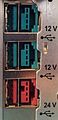
12 V and 24 V USB 1.0 / 2.0 Type A sockets
with high-current 4-pin connections (poweredUSB)
The USB 1.0 / 2.0 type A connector can
clearly be seen in the leading outer pins for the supply voltage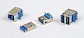
USB 3.0 sockets
v. l. Right: Type B socket, Type A plug, Type A socket, stack with two Type A sockets
USB Y cable
for connecting an external hard drive to two USB 2.0 sockets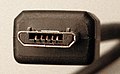
USB 2.0 Micro-B plug
in power supply units widely used for mobile phones
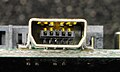
USB 1.0 / 2.0 and USB 3.0 pin header on board

USB 3.0 and USB 1.0 / 2.0 female connector

USB 3.1 Gen 2 connector on a motherboard for connecting a USB-C socket in computer cases.

USB 1.0 / 2.0 Type A socket

USB 1.0 / 2.0 Type B connector

USB 3.0 Type B connector

USB 2.0 mini-B connector
USB 3.0 mini-B socket

USB 3.0 Micro-B connector

USB 3.0 Micro-B socket

USB 3.1 Type-C connector


.jpg)

.jpg)


Mechanical execution
The plugs of a USB cable are protected against polarity reversal and confusion. Flat plugs (type A "DIN IEC 61076-3-107") are used in the direction of the host controller (upstream) . Towards the connected device (downstream) , the cables are either permanently installed or connected via approximately square connectors (type B "DIN IEC 61076-3-108") (occasionally and not in compliance with the standard, also with type A connectors). According to the USB 1.1 to 2.0 standards, USB type A and type B connectors have four cables plus shield. Both connectors should be designed in one of the three colors gray, "natural" (ivory / white) or black. With USB 3.0, new variants of the type A and type B connectors are coming onto the market (see below).
The construction details resulting from the standard can lead to contact problems and damage when the plug is used, especially if it is frequently reconnected: Since there is no screw connection of the sockets and plugs on the circuit board or on the housing, all forces that occur during plugging processes or movements act on the plug and socket, are absorbed by the (less resilient) solder joints of the socket. For this reason, but also because of the lack of locking options , other interfaces are preferred in professional data cabling.
For some time now, plugs and sockets of type A and B have been available with knurled screws that prevent them from slipping out. However, the receiving device must also support this. Various manufacturers occasionally released mechanically incompatible versions of USB connectors, which, however, do not differ electrically from USB 1.x or 2.0, examples:
- "UltraPort" on some IBM Thinkpads
- 10-pin modular sockets (10P10C / RJ50) on the UPS from APC
- Proprietary USB connector on Microsoft's Xbox
- Jack plug that doubles as an audio connector on Apple's iPod Shuffle
variants
| Voltage (in V) |
Load capacity (in W) |
Color coding | |
|---|---|---|---|
| recommended | alternatively | ||
| 5 | 30th | natural color (partly also yellow) | Gray |
| 12 | 72 | blue-green ( Pantone Teal 3262C) | black |
| 19th | 114 | violet | black |
| 24/25 | 144 | red (Pantone Red 032C) | black |
For industrial use, especially in POS applications such as cash register systems , there are other USB connector variants with significantly higher current ratings of up to 6 A (3 A per contact). These variants were not standardized by the USB consortium, but around 1999 in standards , some of which required a license, called Retail USB , PoweredUSB , USB PlusPower or USB + Power by companies such as IBM, Microsoft, NCR and Berg / FCI. Technically, the higher current carrying capacity is realized via four additional cables. While no special connector is defined on the client side (there are, however, various recommendations, some with different hotplug capabilities), the connectors on the host side consist of a combination of a mechanically and electrically unchanged USB type A connector on the one hand and a high-current four-pole connector on the other. Overall, they are almost square, similar to a stack of two USB sockets (see figure above). For the power connector, a mechanical lock is provided between the socket and plug. The power connectors are available in four variants, with mechanical coding preventing different variants from being plugged together.
Micro and mini USB
There are also various more compact USB connectors, particularly for devices with limited space (digital cameras, cell phones, MP3 players and other mobile devices). Only five-pole mini and micro versions (plus shield) are anchored in the USB 2.0 standard and have an additional ID pin compared to normal USB connectors.
First a trapezoidal mini-B connector was defined for the downstream side in 2000, which was to be made in black. For future devices, however, device manufacturers should switch to the micro-USB connector (see below). Mini-A (in white) and mini-AB (in gray) connectors were also part of the standard for a certain time and should play a role in connection with USB On-the-Go (OTG), but were in the Officially withdrawn May 2007. The cables from Mini-B fit into the connector from Mini-AB.
In January 2007, with the standard extension Micro-USB for USB 2.0, even smaller connectors were presented, which enable a particularly compact design of the devices. The micro USB specification can support USB On-the-Go (OTG). Micro-USB connectors are to completely replace the mini-connector in newer devices in the near future (as of January 2009), only the relatively widespread mini-B connector is currently (as of January 2009) still tolerated. The micro-USB connectors are electrically equivalent, but mechanically not plug-compatible, but made much more stable thanks to the stainless steel cramp required in the standard. According to the USB 2.0 standard, there are three variants, all of which are five-pole, just like mini-USB: Micro-A (rectangular design, for the host side, color white), Micro-AB (rectangular design, for USB On-the-Go devices, color gray) and Micro-B (trapezoidal design, for the device side, color black). The Open Mobile Terminal Platform (OMTP) adopted Micro-USB in 2007 as the standard connector for data transfer and the power supply of cellular devices. In China, cell phones have since been equipped with this interface in order to be approved. With USB 3.0, new variants of the Micro-A, AB and B connectors are coming onto the market (see below).
There is also a whole range of proprietary, i.e. device manufacturer-specific miniature connector designs (see also the first picture in the gallery), which are usually electrically compatible with USB 2.0, but only via adapter cables with USB components according to the USB that are sometimes difficult to obtain -Standard can be connected. However, these connectors are often incorrectly referred to as “mini” USB, which repeatedly leads to misunderstandings and should be avoided. A wide variety of designs are widespread
- 4 pins, especially variants from Mitsumi, Aiptek, Hirose
- 8 pins in a large number of variants, including several incompatible variants that have spread in digital cameras to a limited extent even beyond manufacturer limits
- 11 pins for ExtUSB for HTC mobile phones ; compatible with mini USB
- 12 pins for various Olympus digital cameras and
- 14 pins in two versions for various Fuji Finepix digital cameras and as Nokia's Pop port for some mobile phones. In addition to the USB signals, these combine other signals (e.g. analog video and audio for digital cameras) in the same connector.
For power supplies in the device class of smartphones, the European standard EN 62684: 2010 has required micro-USB plugs across Europe since 2011 to curb this diversity (see micro-USB standard ).
As part of the USB 3.0 standard adopted in 2008, a further six connector types with additional contacts were defined:
These are divided into three connectors each, which can be viewed as largely backward-compatible extensions of the previous type A and type B connectors (called: USB 3.0 Standard-A, USB 3.0 Standard-B and USB 3.0 Powered-B) and three smaller connectors that are based on the previous Micro-USB connectors (called: USB 3.0 Micro-A, USB 3.0 Micro-AB and USB 3.0 Micro-B). For clear identification, the previous connectors are now referred to as USB 2.0 Standard-A, USB 2.0 Standard-B, USB 2.0 Micro-A, USB 2.0 Micro-AB and USB 2.0 Micro-B. For better differentiation, the USB 3.0 standard A connectors should be blue (Pantone 300C) and, if necessary, marked with a double S symbol.
USB type C
In August 2014, the specification of the new Type-C connector, which is not compatible with previous hardware, was adopted. The new plug connection is point-symmetrical and can be inserted in both possible orientations.
It also supports all previous transmission specifications including USB 3.1 (up to 10 Gbit / s) and USB Power Delivery (maximum 100 W). Another advantage of the Type-C connector is the low overall height and width of the socket of 8.4 mm, compared to approx. 12.4 mm for a USB 3.0 Micro-B socket, as is the case with practically everyone today external USB 3.0 hard drives is used. The Type-C plug connection is therefore also better suited for portable devices such as smartphones, tablets or digital cameras, in which the USB 2.0 Micro-B socket was previously mostly used for reasons of space. There are also adapters and suitable accessories, such as B. external hard drives.
Problems with USB Type-C cables
As it became known through press releases at the beginning of 2016, problems with USB Type-C cables due to poor manufacturing and the resulting exceeding of specifications are increasing, which can cause irreversible damage to the devices connected to them.
Web pages have now been published listing non-hazardous USB Type-C cables.
USB Type-C authentication program
In 2016, the non-profit organization USB-IF, responsible for the marketing and specifications of the USB standard, announced the USB Type-C Authentication Program , which defines cryptographic authentication. Authentication is intended to prevent damage to devices.
Specifications
| Socket type | Connector type | ||||||||||||
|---|---|---|---|---|---|---|---|---|---|---|---|---|---|
| USB 2 standard A |
USB 3 standard A |
USB 2 standard B |
USB 3 standard B |
USB 3 Powered-B |
USB 2 mini-A |
USB 2 mini-B |
USB 2 Micro-A |
USB 2 Micro-B |
USB 3 Micro-B |
USB 3.1 Type C |
|||
|
|
|
|

|

|
|
|
|
|
|
|
|||
| USB 2 standard A | Yes | Yes | No | No | No | No | No | No | No | ||||
| USB 3 standard A | Yes | Yes | |||||||||||
| USB 2 standard B | No | Yes | No | ||||||||||
| USB 3 standard B | |
No | Yes | Yes | No | ||||||||
| USB 3 Powered-B | |
No | Yes | Yes | Yes | ||||||||
| USB 2 mini-AB | No | Yes | Yes | No | |||||||||
| USB 2 mini-B | No | Yes | |||||||||||
| USB 2 Micro-AB | No | No | Yes | Yes | |||||||||
| USB 2 Micro-B | No | Yes | |||||||||||
| USB 3 Micro-B | No | Yes | Yes | ||||||||||
| USB 3.1 Type C | No | Yes | |||||||||||
| Connection type | USB version | Minimum number of mating cycles | Connection type | Minimum number of mating cycles | |
|---|---|---|---|---|---|
| Standard USB | USB 1.1-2.0 | 500 ×, later 1,500 × | For comparison: | ||
| Standard USB | USB 3.0 | Standard Class: 1,500 ×, High Durability Class: 5,000 × | eSATA | 5,000 × | |
| Mini USB | USB 2.0 | 5,000 × | Firewire / IEEE 1394 | 1,500 × | |
| Micro USB | USB 2.0-3.0 | 10,000 × | |||
| USB-C | USB 2.0-3.1 | 10,000 × | |||
| plug | Connector dimensions | matching sockets |
permitted cable types |
|---|---|---|---|
| A. |

|
A. | → Connector B → Connector Mini-B → Connector Micro-B |
| B. |

|
B. | → Connector A |
| USB 3.0 B |

|
USB 3.0 B | → Connector USB 3.0 A → Connector A |
| Mini-B |

|
Mini-B | → Connector A |
| Micro-A |

|
Micro AB | → plug Micro-B → socket A (as adapter) |
| Micro-B |

|
Micro-B Micro-AB USB 3.0 Micro-B |
→ Connector A → Connector Micro-A |
| USB 3.0 Micro-B |

|
USB 3.0 Micro-B | → USB 3.0 A connector → USB 3.0 Micro-A connector |
In addition, various variants of pin headers with a grid dimension of 2.54 millimeters (= 100 mil ) on PC mainboards, predominantly with 1 × 4, 1 × 5 and 2 × 2 pins or for double USB connectors with 2 × 4 or 2 × 5 pins. While there were initially several mutually incompatible assignment variants, in the course of newer motherboard specifications from Intel, a certain 2 × 5-pin assignment has now been established that is also compatible with USB flash modules .
USB cable


Four wires are required in a USB 2.x cable. Two wires transfer the data while the other two provide the connected device with a voltage of 5 V . Devices conforming to the USB specification may draw up to 100 mA or 500 mA from the bus, depending on how much the port to which they are connected can deliver. Devices with an output of up to 2.5 W can therefore be supplied via the bus. Depending on the cable length, the cross-section of the two power supply cores must be adapted in order to maintain the permissible voltage drop; this is one of the reasons why extension cables are not standard.
The cables must be shielded differently depending on the speed . Cables that only meet the Low Speed specification must not have a B connector, but must be permanently attached to the device or use a manufacturer-specific connector. They are less strongly shielded, do not have any twisted wires and are therefore more flexible than full / hi-speed cables. They are therefore well suited for mice and keyboards, for example. The poor shielding of the cable would cause problems with devices running at higher speeds.
The lengths of full / hi-speed and low-speed cables from the hub to the device are limited to five and three meters, respectively. Longer distances can be overcome by connecting USB hubs. USB repeater cables correspond in their functions to a bus-powered hub (see below) with a single downstream port and a permanently connected cable to the upstream port. Since the electrical effects of these cables in the USB bus correspond to those of a bus-powered USB hub with a five-meter cable, the restrictions on cascading USB hubs must also be observed when using them.
USB works with a wave impedance of 90 Ω. Direct connection cables should therefore also have this characteristic impedance value. USB line extenders are available for bridging lengths over 30 meters. These consist of two components: a base module that is connected to the computer and a remote module for connecting the USB device. Ethernet cables or light guides are usually used to bridge the distance between these two components. However, since these line extenders always rely on certain behavior details of the connected devices that are not prescribed by the standard, and the signal delay leads to protocol violations over long cable runs, the use of these devices is often associated with problems.
Another possibility of connecting USB devices further away from the computer are solutions that use a "remote host", ie a USB host controller that is located outside the PC. Communication between the PC and host controller takes place via Ethernet, for example . The Ethernet replaces the local bus to which the host controller would otherwise be connected. So only a corresponding driver has to be installed on the PC, which takes over the communication with the host controller. Drivers for the USB devices then do not recognize any difference to a locally connected device. Examples of such a device are the USB server from Keyspan and the USB remote connection function of a Fritz! Box .
Contact assignment and wire colors
In addition to the assignment of the connectors, the USB standard also specifies the names of the individual signals; only recommendations are made for the wire color. In fact, the wire colors used vary from manufacturer to manufacturer. The number of a plug pin can be read from the schematic drawings above.

| Pin code | Signal name | Wire color | description |
|---|---|---|---|
| casing | umbrella | n / A | Braided shield |
| 1 | VBUS | red | +5 V |
| 2 | D− | White | Data USB 2.0, differential pair - / + |
| 3 | D + | green | |
| 4th | GND | black | Dimensions |

| Pin code | Signal name | Wire color | description |
|---|---|---|---|
| casing | umbrella | n / A | Braided shield |
| 1 | VBUS | red | +5 V |
| 2 | D− | White | Data USB 2.0, differential pair - / + |
| 3 | D + | green | |
| 4th | ID | no vein | allows distinction between Micro-A and Micro-B plugs: Type A: Ground ( On-The-Go ; [OTG] device works as host) Type B: not connected (OTG device works as a peripheral) |
| 5 | GND | black | Dimensions |
| Pin code | Signal name | Wire color | description | |
|---|---|---|---|---|
| Connector A | Connector B | |||
| casing | umbrella | n / A | Braided shield | |
| 1 | VBUS | red | +5 V | |
| 2 | D− | White | Data USB 2.0, differential pair - / + | |
| 3 | D + | green | ||
| 4th | Dimensions | black | Ground for +5 V. | |
| 5 | StdA_SSRX− | StdB_SSTX− | blue | Data SuperSpeed, transmitter, differential pair - / + |
| 6th | StdA_SSRX + | StdB_SSTX + | yellow | |
| 7th | GND_DRAIN | uninsulated | Mass for data SuperSpeed; One wire for each differential SuperSpeed pair, but connected to the same pin | |
| 8th | StdA_SSTX− | StdB_SSRX− | violet | Data SuperSpeed, receiver, differential pair - / + |
| 9 | StdA_SSTX + | StdB_SSRX + | orange | |
| 10 | n / A | DPWR | no specification | Power supply for device (only in connector USB 3 Powered-B) |
| 11 | n / A | DGND | no specification | Ground for DPWR (only in connector USB 3 Powered-B) |
| Type-C connector 1 | Type-C cable | Type-C connector 2 | |||||
|---|---|---|---|---|---|---|---|
| Pin code | Surname | Wire color | Surname | description | Pin code | Surname | |
| casing | umbrella | n / A | umbrella | Braided shield | casing | umbrella | |
| A1, B1, A12, B12 |
GND | Tinned | GND_PWRrt1 GND_PWRrt2 |
Dimensions | A1, B1, A12, B12 |
GND | |
| A4, B4, A9, B9 |
V BUS | red | PWR_V BUS 1 PWR_V BUS 2 |
V BUS voltage | A4, B4, A9, B9 |
V BUS | |
| B5 | V CONN | yellow | PWR_V CONN | V CONN voltage | B5 | V CONN | |
| A5 | CC | blue | CC | Configuration channel | A5 | CC | |
| A6 | Dp1 | White | UTP_Dp | Unshielded twisted pair , positive | A6 | Dp1 | |
| A7 | Dn1 | green | UTP_Dn | Unscreened twisted pair, negative | A7 | Dn1 | |
| A8 | SBU1 | red | SBU_A | Sideband usage A | B8 | SBU2 | |
| B8 | SBU2 | black | SBU_B | Sideband usage B | A8 | SBU1 | |
| A2 | SSTXp1 | Yellow * | SDPp1 | Shielded twisted pair cable 1, positive | B11 | SSRXp1 | |
| A3 | SSTXn1 | Brown * | SDPn1 | Shielded twisted pair 1, negative | B10 | SSRXn1 | |
| B11 | SSRXp1 | Green * | SDPp2 | Shielded twisted pair cable 2, positive | A2 | SSTXp1 | |
| B10 | SSRXn1 | Orange * | SDPn2 | Shielded twisted pair cable 2, negative | A3 | SSTXn1 | |
| B2 | SSTXp2 | White * | SDPp3 | Shielded twisted pair 3, positive | A11 | SSRXp2 | |
| B3 | SSTXn2 | Black * | SDPn3 | Shielded twisted pair 3, negative | A10 | SSRXn2 | |
| A11 | SSRXp2 | Red * | SDPp4 | Shielded twisted pair 4, positive | B2 | SSTXp2 | |
| A10 | SSRXn2 | Blue * | SDPn4 | Shielded twisted pair 4, negative | B3 | SSTXn2 | |
| * Wire colors for the shielded twisted cable pairs are not specified | |||||||
| A12 | A11 | A10 | A9 | A8 | A7 | A6 | A5 | A4 | A3 | A2 | A1 |
| GND | RX2 + | RX2− | VBUS | SBU1 | D− | D + | CC1 | VBUS | TX1− | TX1 + | GND |
| GND | TX2 + | TX2− | VBUS | CC2 | D + | D− | SBU2 | VBUS | RX1− | RX1 + | GND |
| B1 | B2 | B3 | B4 | B5 | B6 | B7 | B8 | B9 | B10 | B11 | B12 |
USB hubs
General


A USB hub is a USB device that distributes the USB signal to multiple ports. USB hubs with up to seven downstream ports are common, but hubs with up to 28 ports can also be found here and there.
Hubs can get their power from the bus themselves (called bus-powered or passive hubs ) or have their own power supply (called self-powered or active hubs ). Most self-powered hubs are powered by a plug-in power supply. Some monitors also have a built-in USB hub that is fed from the monitor's power supply. Self-powered hubs have the advantage that each device connected to them can draw up to 500 mA of current. With bus-powered hubs, the hub and all devices connected to it may collectively draw a maximum of 500 mA. Hybrid self- and bus-powered hubs are possible - the hub is self-powered when a power supply unit is connected to it, otherwise bus-powered.
When nesting hubs, the limits are set by the maximum of 127 possible USB devices per root hub and by the signal runtime - each hub increases the runtime, the nesting depth is limited to a maximum of five (hub) levels below the host controller or the root Stroke limited. Due to the limitation of 5 m per USB cable, the maximum distance between two USB-connected devices is 30 m - six cables each five meters long and five hubs in between.
With integrated components for USB hubs, the equipment with four ports dominates (this applies in particular to components in rather inexpensive hubs). If a larger number of USB connections is required, several modules can be cascaded. As a result, such a hub occupies several USB addresses and is equivalent to at least two hubs connected in series.
USB 2.0 and hubs
Low, full and hi-speed devices can be mixed almost at will on a USB 2.0 host without any speed disadvantages. Hubs based on the USB 1.x standard can be used on USB 2.0 hosts. Devices that are connected directly or indirectly to such a hub can only achieve full speed , i.e. 12 Mbit / s. A USB 2.0 host and a USB 2.0 hub always communicate at Hi-Speed, even if low-speed or full-speed devices are connected to the hub. It is the task of the hub to pack the data from these devices into the Hi-Speed protocol; for this purpose it has built in one or more transaction translators . The number of Transaction Translators determines how many slow devices can be connected to a USB 2.0 hub without slowing each other down. If this number is exceeded, the data rate of all low-speed and full-speed devices connected to this host drops to speeds well below those of a USB 1.1 host; however, the throughput of Hi-Speed devices on the same hub remains unaffected. The specification of the power consumption has not changed with USB 2.0 compared to USB 1.1.
USB 3.0 and hubs
There is a new hub concept under USB 3.0. Hubs consist of two sub-hubs. One is specifically responsible for the new SuperSpeed mode, the other for the previous speed modes (Low Speed, Full Speed, Hi-Speed). Both parts are only brought together at the ports. In December 2009 VIA presented the first chips for USB 3.0 hubs. The chip called VL810 is compatible with all speed modes.
USB switch
A USB switch (also known as a USB switch or USB switch) is a device for operating a peripheral device on several computers without having to plug it in. A USB hub can also be connected downstream of the switch or it can be located in the same housing.
Only one of the computers can be switched to the respective peripheral devices here. This is done either by a manual switch or automatically. B. switching on a computer and the accompanying USB power supply, the switchover.
USB card bus

The Cardbus standard (PC Card Standard 5.0) was originally developed for PCMCIA cards as a data storage medium , but differs from the PCMCIA standard in that it has a completely different architecture. There are also plug-in cards with CardBus controllers available on the market that convert USB into CardBus so that USB plugs can also be used, for example, on mobile devices without an integrated USB interface - but they are limited to the 32-bit CardBus. Retrofitting computers with a 16-bit bus is therefore not possible. CardBus has been replaced by the newer and more powerful ExpressCard standard.
Galvanic separation
In certain areas of application, such as in industrial environments or in medical technology , it may be necessary to provide galvanic separation between different USB devices in order to avoid problematic ground loops . In addition to the supply lines for the interface, this also includes the data lines using DC voltage converters with galvanic isolation. Since the data lines are operated bidirectionally up to Hi-Speed (480 Mbit / s), the electrical isolation of the interface requires corresponding additional control logic for controlling the driver stages, which is combined in integrated circuits and referred to as a USB isolator . This reduces the achievable data rate with USB isolators.
Software architecture
All USB transactions are realized by the USB software on the host computer. This is done by the respective USB device driver that wants to communicate with his device. The USB bus driver is the interface between the USB device driver and the USB host controller.
USB bus driver
The USB bus driver (USB driver) knows the specific communication properties of the individual USB devices, for example the amount of data per frame or the intervals between periodic accesses. It recognizes these properties when analyzing the device descriptors during the configuration phase. When the USB bus driver receives an IRP from a USB device driver, it generates individual transactions according to this request, which can be carried out within the transmission frame (frame) of one millisecond.
USB host controller driver
The USB host controller driver organizes the chronological sequence of the individual transactions (scheduling). To do this, he builds up a sequence of transaction lists. Each of these lists consists of the transactions that have not yet been processed in the direction of a device that is connected to the bus. It defines the order of transactions within the 1 ms time frame. The USB bus driver can split a single request for a data transfer into several transactions. Scheduling depends on a number of influencing factors such as type of transfer, device properties and bus load. The USB host controller driver then initiates the transactions via the root hub. This implements all transactions in the current list one after the other.
Support in operating systems
- Amiga OS4.x supports USB 1.1 from version 4.0. Since the AmigaOS4.1 Update3 it also supports USB 2.0.
- Amiga OS3.x does not support USB by default. USB 1.1 and USB 2.0 devices can only be connected with hardware and software from other providers (Poseidon, Sirion, Anaiis) (with broad support for various device classes from Poseidon). With Poseidon, you can even boot from USB mass storage devices in conjunction with a Flash ROM card. From Amiga OS4 - depending on the hardware - USB 1.1 and 2.0 is supported (no USB 2.0 Hi-Speed, as the EHCI driver is still missing). Alternatively, Poseidon can also be used under AmigaOS 4 Classic.
- AROS contains an open source port of Poseidon since August 2009, which replaces the old implementation. It supports OHCI / UHCI (USB 1.1) and EHCI (USB 2.0 Hi-Speed) as well as most of the device drivers available in Poseidon for AmigaOS. The stack is (partly) in the kernel and can be used to boot from USB mass storage devices.
- Atari MiNT does not support USB by default, but various drivers are being developed for MiNT that support add-on cards (such as EtherNAT, a combination of USB and Ethernet expansion for the Atari Falcon).
- As the successor to OS / 2 , eComStation also has support for USB 2.0.
- FreeBSD supports from version 3.0 OHCI and UHCI controllers (USB 1.1), from version 5.2 EHCI (USB 2.0) and from version 8.2 also XHCI (USB 3.x). There are drivers for USB devices such as keyboards, mice, printers, TV receivers, cameras, Ethernet, WLAN, mass storage devices, smartphones, serial interface adapters and many more. A completely new USB implementation was released in FreeBSD 8.0 that had affected the driver situation for a while. In the current version, however, the problem no longer exists.
- The Linux kernel supports USB 1.1 controllers from version 2.2.7 (1999). Since the kernel version 2.4, drivers for UHCI, OHCI (USB 1.1) and EHCI controllers (USB 2.0) as well as support for common USB devices have been integrated. The support for EHCI controllers in the kernel version 2.4 (2001) is however prone to errors and is only stable from version 2.6 (2003). There are also gadget drivers so that a Linux-based system that is connected to a USB host can itself appear as a USB device, for example as a mass storage device, network card or serial interface. From version 2.6.31 (2009) USB 3.0 is also supported by the Linux kernel.
- Mac OS supports USB 1.1 from Mac OS 8.1 (1998). Over time, the range of devices supported with class drivers has expanded significantly; from Mac OS 8.5 (also 1998) onwards, most common device classes are supported.
- macOS (from 1999 to 2012 “Mac OS X” or up to 2016 “OS X”) supports USB 1.1 in all versions and from version 10.2.8 also USB 2.0. As of OS X 10.8 ( Mountain Lion , 2012), USB 3.0 is also supported on Macs that are factory-equipped. With the appropriate driver, there is also the option of using expansion cards with USB 2.0 and 3.0 under earlier Mac OS X versions.
- MorphOS is supplied with the Poseidon USB stack with full support for UHCI, OHCI and EHCI (not all drivers support isochronous transfer).
- MS-DOS and compatibles do not support USB by default. USB keyboards and USB mass storage are on the Legacy - emulation of many modern PC BIOS yet capable versions, but usually not hot plug capable. USB mice also usually work with drivers designed for PS / 2 mice when legacy mode is activated. For FreeDOS there is the “motto hairu” driver, which provides USB 2.0. Other manufacturers offer special drivers that use a lot of conventional memory and are therefore not compatible with many DOS programs.
- NetBSD and OpenBSD support UHCI, OHCI and EHCI as well as common end devices. In 1998, NetBSD was the first free operating system with USB support.
- OS / 2 Warp 4 only supports USB 1.1 via the upgrade pack Warp 4.51 Convenience Pack 1 (from December 2000). This is chargeable. Driver updates to USB 2.0 are also available.
- Palm OS from version 3.2 supports USB as a communication platform for HotSync , from Palm OS 5 (partly with additional programs) modem functions can also be used via USB. Certain PDAs (such as Sony Clié) can emulate a mass storage device with the USB interface.
- QNX supports from version 6 UHCI, OHCI and EHCI, with separately available drivers USB support can also be retrofitted in QNX4. The drivers supplied are limited to the HID boot mode, some RS232 and Ethernet adapters and mass storage devices.
- As of OEM Service Release 2.1, Windows 95 has rudimentary support for USB 1.0, which is considered so defective that use is usually not possible.
- Windows 98 supports USB 1.0, from Windows 98 SE also USB 1.1. USB 2.0 is only possible with drivers from chipset manufacturers.
- Windows Me supports USB 1.1 and is the only system in the 9x series to have a generic device driver for mass storage devices. USB 2.0 is only possible with drivers from chipset manufacturers. In contrast to Windows 98 and 95, no restart is required after installing device-specific USB drivers.
- Windows NT 4.0 has no USB support whatsoever, but system expansions are available from other manufacturers. Device manufacturers rarely test their products with such extensions, which is why these system extensions are only suitable for special cases.
- Windows 2000 (SP4), Windows XP (from SP1), Windows Server 2003 , Windows Vista , Windows Server 2008 , Windows 7 and Microsoft Windows Server 2008 R2 support USB 1.1 and USB 2.0 and generically support mass storage devices right from the start. However, because the USB host controller is sometimes incorrectly recognized, most manufacturers recommend installing the drivers from the chipset manufacturer.
- Windows 8 supports USB 1.0, 1.1, 2.0, 3.0.
- Windows 10 supports USB 1.0, 1.1, 2.0, 3.0, 3.1.
PCs can use the BIOS to enable (older) operating systems without USB support to use USB input devices such as mice and keyboards. To do this, activate “USB Legacy Support ” (English for about “USB support for legacy systems”), whereby the USB devices appear as PS / 2 devices to the operating system . The settings required for this are called differently in each BIOS variant, for example simply "USB Keyboard Support". Also a start of USB storage devices is made possible by most firmware implementations. Under Open Firmware on Apple Macintosh computers with PowerPC processors, there is e.g. B. a firmware command, which can be started from a connected USB mass storage device. On PCs with BIOS, exactly one USB drive (such as USB stick, USB card reader, USB hard drive, USB floppy) is usually integrated; Additional USB drives are only integrated if the starting operating system itself supports USB. Older firmware (including BIOS on computers up to 1995) cannot handle USB. With the latest firmware it can be assumed that USB can be used for input devices (keyboard, mouse) as well as for the start medium. UEFI, for example, fully supported USB from the start.
Security issues
At Black Hat 2014 , Karsten Nohl and Jakob Lell explained the security risks of USB devices. Many USB controller chips in USB devices can be reprogrammed. There is no effective protection against rewriting, so that an apparently harmless USB device can be misused as a harmful device. A USB device can:
- emulate a keyboard and commands on behalf of the logged-in user, thus installing malware and infecting connected USB devices.
- impersonate a network card, change the DNS setting in the computer and redirect data traffic.
- Load a small virus during the boot process, which infects the operating system before it boots.
Such attacks have so far been difficult to defend against because malware scanners do not check the firmware in USB devices and behavioral detection is difficult. USB firewalls that only block certain device classes do not yet exist. MacOS offers a certain protection when plugging in a USB device recognized as a keyboard by asking whether you want to activate the keyboard. The usual removal of malware - by reinstalling the operating system - is of no use, as a USB storage device from which it is installed may already be infected. Other USB devices are also unaffected by reinstalling the operating system and therefore still contain the malware. It should be noted that USB is also widely used as an internal interface for connecting permanently installed peripheral components (such as a webcam in the laptop lid).
In October 2014, security researchers Adam Caudill and Brandon Wilson presented modified firmware and tools for repairing damage at the DerbyCon conference .
USB as a standardized voltage source

In addition, USB is sometimes used as a standardized voltage source. In 2009, for example, following pressure from the EU Commission , well-known mobile phone manufacturers agreed to use micro-USB as the standard device socket for the charging contact. Occasionally, manufacturers of other small electronic devices such as compact digital cameras have followed suit - in the field of (portable) media players (especially MP3 players ) charging via USB interface was already widespread.
The USB standard provides that devices first start in low-power mode (100 mA or 150 mA) and, if more power is required, request this from the host before switching to normal mode. With USB 2.0 this can be up to another four times 100 mA, with USB 3.0 up to another five times 150 mA. If this request fails, the device must switch off. Most of the devices mentioned above, however, only use the USB port as a voltage source without being asked and violate the USB standard by drawing more than 100 mA of current without the host's permission. In extreme cases, this could damage the host's USB connection or disrupt the computer's energy management, which can lead to unstable behavior. Economical 2.5-inch hard drives can usually be operated with 2.5 W (500 mA) on a 2.0 USB port with an adapter, but larger 3.5-inch hard drives cannot. There are also economical notebook CD / DVD / Bluray burners that can be operated via the USB port. However, their power consumption is far outside the USB specification, especially when burning at higher speeds with sometimes permanently over 1000 mA.
There are now power supplies that provide 5 V to a USB-A socket or a cable with a micro-USB-B connector. The available current is usually 1000 mA (generally between 500 and 2500 mA). The USB Battery Charging Specification is generally used as a reference for smartphones (this should not be confused with the energy management that takes place during the enumeration process when connecting to a USB host). This standardizes the wiring of the data lines so that there is a uniform configuration and, if possible, all smartphones can be charged with one and the same power supply unit. However, not all smartphone manufacturers adhere to this requirement, so that certain devices cannot be charged with every power supply unit (e.g. Apple). If a device is charged on a USB host (e.g. PC / notebook) rather than on a power supply unit built for this purpose, commands relating to energy management are exchanged during the enumeration. The latter is necessary if the device to be charged adheres exactly to the USB standard and only draws the power that has been approved for it. A well-known representative is the iPhone : It recognizes that it is being charged on a power supply unit when certain voltage levels are present on the data lines. Instead, a computer uses energy management to negotiate how much electricity the device is allowed to draw.
Oddities

Fancy devices have also come onto the market that primarily use USB for power supply. For example, there are USB hot plates that can be used to keep a coffee cup warm via the USB interface, USB lamps for notebooks to illuminate the keyboard, USB keyboard vacuum cleaners, USB fans, rotors with LED light effects, USB -Christmas trees or heated USB gloves, USB butt plugs , USB hearing aid dryers and USB slippers.
Ajay Bhatt was singled out among the group of developers of the USB standard when he appeared in the commercial Ajay Bhatt - The Real USB Rock Star! of the Intel company was portrayed as a rock star.
literature
- Hans-Joachim Kelm: USB 2.0 . Franzis, Poing 2006, ISBN 3-7723-7965-6 .
- Jan Axelson: USB Complete. Everything You Need to Develop Custom USB Peripherals . 4th edition. Lakeview Research, Madison 2009, ISBN 978-1-931448-08-6 .
- German: USB 2.0. Developer Guide . 3. Edition. mitp, Heidelberg 2007, ISBN 978-3-8266-1690-7 .
- Bernhard Redemann: Controlling and measuring with USB, hardware and software development with the FT232, 245 and 2232 . Self-published, Berlin 2006, ISBN 3-00-017884-8 .
Web links
Remarks
- ↑ The asymmetry due to the pull-up and pull-down resistors with which the peripheral device displays the data rate it supports can be neglected here due to the high values of these resistors; the resistance values are more than an order of magnitude above the wave resistance of the line.
Individual evidence
- ↑ usb.org ( Memento from May 14, 2009 in the Internet Archive )
- ↑ a b USB 3.2: USB-C speed doubled to 20 GBit / s - Heise , on September 27, 2017
- ↑ a b Interface: USB 3.2 doubles the data rate to 20 GBit / s - Golem , on July 26th 2017
- ↑ USB (Universal Serial Bus). (No longer available online.) Historical and cultural information processing, archived from the original on December 31, 2015 ; accessed on November 12, 2015 : “Despite its name - Universal Serial Bus - the USB is not a physical data bus.” Info: The archive link was automatically inserted and not yet checked. Please check the original and archive link according to the instructions and then remove this notice.
- ↑ Retrofitting a DVI output via USB - Heise , June 5, 2007
- ↑ 1394 Monthly Newsletter . Information Gatekeepers Inc ( google.at [accessed January 4, 2019]).
- ↑ Sven Hesse: USB 3.0 is coming in 2009 with 4.8 Gbit / s . ( Memento of the original from December 20, 2008 in the Internet Archive ) Info: The archive link was inserted automatically and has not yet been checked. Please check the original and archive link according to the instructions and then remove this notice. Allround-PC.com, November 21, 2008.
- ↑ USB 3.1: Starting shot for developers. at heise.de . 1 August 2013.
- ↑ Seth Colaner, Niels Broekhuijsen: All Things USB 3.1 And USB Type-C: An Explainer . tomshardware.com from August 27, 2015.
- ↑ SuperSpeed USB. ( Memento of the original from May 14, 2009 in the Internet Archive ) Info: The archive link was automatically inserted and not yet checked. Please check the original and archive link according to the instructions and then remove this notice. USB Implementers Forum, Inc., accessed January 3, 2016.
- ↑ USB 3.2 or “SuperSpeed USB 20Gbps” should come in 2019. February 27, 2019, accessed February 27, 2019 .
- ↑ USB Promoter Group USB4 Specification. In: usb.org. August 29, 2019, accessed May 15, 2020 .
- ↑ heise: USB4 gets hub topology. March 6, 2019, accessed May 15, 2019 .
- ↑ USB 2.0 ECN VBUS Max Limit.pdf
- ↑ a b Oliver Ehm: Power supply for the USB connection . Com-Magazin.de, February 22, 2012.
- ↑ a b c d e USB-PD - USB Power Delivery. In: www.elektronik-kompendium.de. Retrieved August 10, 2018 .
- ↑ a b Battery Charging Specification - Revision 1.2. (No longer available online.) USB Implementers Forum, December 7, 2010, archived from the original on March 28, 2016 ; accessed on August 20, 2016 . Info: The archive link was inserted automatically and has not yet been checked. Please check the original and archive link according to the instructions and then remove this notice.
- ↑ usb.org ( page no longer available , search in web archives ) Info: The link was automatically marked as defective. Please check the link according to the instructions and then remove this notice.
- ↑ usb.org ( Memento of the original from April 4, 2016 in the Internet Archive ) Info: The archive link was inserted automatically and has not yet been checked. Please check the original and archive link according to the instructions and then remove this notice. (PDF)
- ↑ eXtensible Host Controller Interface for Universal Serial Bus (xHCI). (PDF) Revision 1.1. Intel Corporation, December 20, 2013, p. 500 , accessed September 22, 2016 .
- ↑ USB specification 2.0 page 153
- ↑ USB Class Codes ( Memento of April 2, 2007 in the Internet Archive ) . usb.org. November 17, 2009
- ↑ USB specification 2.0, p. 46.
- ↑ USB specification 2.0 page 55
- ↑ a b Benjamin Benz: Fast as an arrow - the third USB generation delivers transfer rates of 300 MByte / s. In: c't . No. 22, 2008, p. 212.
- ↑ USB 2.0 Specification 2.0, 7.1.11 Data Signaling Rate
- ↑ courses.cit.cornell.edu (PDF)
- ↑ a b c d e f USB 3.2 Specification - Language Usage Guidelines from USB-IF. (PDF) Guidelines for Using the USB 3.2 Specification Language. usb.org, accessed January 30, 2020 (the link to this document can be found on the publisher's page https://usb.org/superspeed-usb ).
- ↑ a b Chaim Gartenberg: USB 3.2 standard gets new, even more confusing names ahead of its mainstream debut. February 27, 2019, accessed on May 13, 2020 .
- ↑ synopsys.com
- ↑ Universal Serial Bus Specification Revision 2.0 . April 27, 2000, p. 54-55, Tables 5-9 and 5-10 .
- ↑ Samsung Galaxy S II at samsungmobile.com ( Memento of the original from March 12, 2011 in the Internet Archive ) Info: The archive link was inserted automatically and has not yet been checked. Please check the original and archive link according to the instructions and then remove this notice.
- ↑ General allocation of frequencies for use by low-power applications of ultra-wideband (UWB) technology . (PDF; 94 kB) Federal Network Agency, 2010.
- ↑ Matthias Kremp: Cut the cables - preferably not yet. In: Spiegel Online . January 18, 2008, accessed September 17, 2016 .
- ↑ From USB 1.0 to USB 3.0: The triumphant advance of the Universal Serial Bus. In: player.de , September 25, 2009.
- ↑ Daniel Dubsky: USB 3.0 is ready. (No longer available online.) In: PC Professionell . November 18, 2008, archived from the original on February 14, 2011 ; accessed on September 17, 2016 .
- ↑ USB 3.0 Hard Drives Can Cause Wi-Fi Interference. Accessed December 31, 2015 .
- ↑ Anika Kehrer: Linux supports USB 3.0 . In: Linux Community. June 8, 2009.
- ↑ Nico Ernst: The new USB connector is ready and goes into production. Golem.de , August 12, 2014, p. 2 , accessed on August 12, 2014 .
- ↑ Dominic Jahn: New USB Type-C connection supplies your 4K monitor with video signals. 4kfilme.de , September 23, 2014, p. 1 , accessed October 11, 2014 .
- ↑ Synopsys demo: Prototype of USB 3.2 manages 1,600 MB / s - Golem , on May 29, 2018
- ↑ High-Speed Inter-Chip USB Electrical Specification, Version 1.0 (a supplement to the USB 2.0 specification.), 03/13/2006., Archived copy ( memento of the original from August 25, 2018 in the Internet Archive ) Info: The archive link was created automatically used and not yet tested. Please check the original and archive link according to the instructions and then remove this notice.
- ↑ Inter-Chip Supplement to the USB Revision 3.0 Specification, Revision 1.02, May 19, 2014, archived copy ( memento of the original from August 25, 2018 in the Internet Archive ) Info: The archive link was inserted automatically and has not yet been checked. Please check the original and archive link according to the instructions and then remove this notice.
- ↑ etsi.org
- ↑ PowerdUSB.org (English)
- ↑ Mobile phones to adopt new, smaller USB connector. ( Memento of the original from January 8, 2007 in the Internet Archive ) Info: The archive link was inserted automatically and has not yet been checked. Please check the original and archive link according to the instructions and then remove this notice. (PDF). In: USB Implementers Forum. January 4, 2007 (English, PDF; 128 kB)
- ↑ Mini-A and mini-AB connectors withdrawn . ( Memento of the original from March 6, 2009 in the Internet Archive ) Info: The archive link was inserted automatically and has not yet been checked. Please check the original and archive link according to the instructions and then remove this notice. (PDF) May 2007 (press release by USB-IF), PDF
- ↑ Smaller USB connector for mobile devices - Heise , January 5th, 2007
- ^ OMTP Local Connectivity Recommendations. Common Charging and Local Data Connectivity. In: omtp.org , June 8, 2010 ( Memento of July 25, 2011 in the Internet Archive )
- ↑ Overview of various non-standard miniature USB connectors (English, information page of an adapter cable manufacturer)
- ↑ The new USB plug is ready and goes into production on Golem.de
- ↑ Nico Ernst: Type C - USB gets a new twist-proof connector. Golem.de , December 4, 2013, accessed December 6, 2013 .
- ↑ Type C - USB gets new twist-proof connector. (No longer available online.) Usb.org , February 20, 2014, archived from the original on July 29, 2014 ; accessed on March 15, 2014 (English). Info: The archive link was inserted automatically and has not yet been checked. Please check the original and archive link according to the instructions and then remove this notice.
- ↑ a b Press release on the announcement of USB-C, published on usb.org on August 12, 2014 ( Memento from March 4, 2016 in the Internet Archive ) (PDF)
- ↑ Overview: USB Type-C adapters and products. USB-Type-C News, accessed on March 11, 2015 (German).
- ↑ USB-C Faulty cables become Russian roulette. DerStandard.at, accessed on February 6, 2016 (German).
- ↑ Overview: List of correctly specified Type-C cables. usbccompliant.com, accessed on February 6, 2016 (German).
- ↑ The USB Type-C Authentication Program will help protect against non-compliant USB chargers. In: xda-developers. January 2, 2019, Retrieved January 4, 2019 (American English).
- ↑ USB 3.0 specification. (zip / PDF (32.4 MB)) 5.2.2 Compliant Cable Assemblies. (No longer available online.) USB Implementers Forum, Inc., May 1, 2011, p. 79 , archived from the original on September 10, 2013 ; accessed on November 8, 2013 . Info: The archive link was inserted automatically and has not yet been checked. Please check the original and archive link according to the instructions and then remove this notice.
- ↑ a b USB 3.0 Interface Bus, Cable Diagram. Retrieved May 15, 2020 . 100806 interfacebus.com
- ↑ usb.org ( Memento of the original from February 4, 2016 in the Internet Archive ) Info: The archive link was inserted automatically and has not yet been checked. Please check the original and archive link according to the instructions and then remove this notice.
- ↑ thinkgeek.com accessed July 1, 2013
- ↑ Andreas Link: USB 3.0: All information about the new technology standard . In PC Games Hardware , January 25, 2010.
- ↑ Christoph Windeck: PC card and USB (practice / hotline) . In: c't . No. 14 , 2003, p. 204 .
- ↑ Alexander von Obert: Can I retrofit a USB interface? In: USB memory stick (USB memory module) FAQ - Part 1: Hardware. December 21, 2007, accessed March 27, 2008 .
- ↑ ADuM4160: Full / Low Speed 5 kV USB Digital Isolator. (PDF) Analog Devices, company publication, February 2012, accessed on March 6, 2017 .
- ↑ Linux kernel 2.6.31 supports USB 3.0. In golem.de , September 10, 2009.
- ↑ Marc Sauter: Windows 10 supports USB Type C . Golem.de, March 20, 2015, accessed October 8, 2015.
- ↑ BadUSB - On Accessories that Turn Evil by Karsten Nohl + Jakob Lell. Black Hat, August 11, 2014, accessed September 15, 2014 .
- ↑ Black Hat USA 2014 Briefings. Retrieved September 15, 2014 .
- ↑ a b c d e f g h i Turning USB peripherals into BadUSB ( Memento from April 18, 2016 in the Internet Archive ) Security Research Labs (English)
- ↑ Patrick Beuth: Any USB device can become a weapon. Die Zeit , July 31, 2014, accessed on September 15, 2014 .
- ↑ Ronald Eikenberg: BadUSB tools are circulating on the net, self-made attack stick. October 3, 2014, accessed October 16, 2014 .
- ↑ Commission welcomes industry agreement on a universal charger for mobile phones . European Union press release, June 29, 2009.
- ↑ Hearing aid dryer accessed on January 30, 2020.
- ↑ Ian Chiu: Ajay Bhatt - The Real USB Rock Star! (No longer available online.) May 8, 2009, archived from the original on April 3, 2014 ; accessed on September 17, 2016 .
- ↑ Mike Magee: Intel turns USB man into rock star . In TG Daily , May 7, 2009.