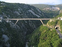
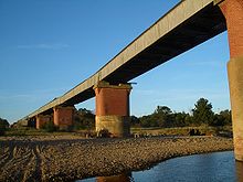
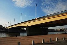
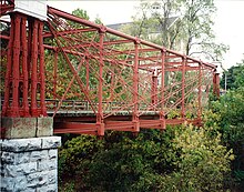
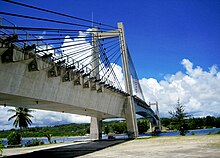
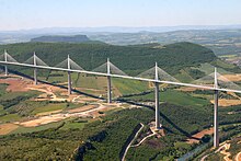
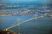
Technical classification of bridges
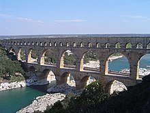
A classification of bridges can be technically - the technical classification of bridges - according to different criteria : according to function, supporting structure , durability of the transition, size of the bridge, type of obstacle overcome or span.
Classification according to function
The function of a bridge depends on the connection it makes:
| designation | image | description |
|---|---|---|
| Road bridge | Road bridges are structures that support a road . The highway bridges that support the highways belong to the road bridges. | |
| Railway bridge | Railway bridges carry railways or trams . | |
| footbridge | A pedestrian bridge (also a passerelle in Switzerland ) carries a footpath for pedestrians , and in many cases also a cycle path . | |
| aqueduct | An aqueduct carries a water channel or a water pipe, whereby the term sometimes describes the entire system for transporting the water, including the parts that are not on a bridge. The terms oluct and gas product , on the other hand, always refer to the entire structure for the transport of oil or gas and not just a bridge. | |
| Canal bridge | A canal bridge describes a structure that supports a shipping canal . | |
| Taxiway bridge | A taxiway bridge or taxiway bridge for airplanes enables airports to be extended across streets, for example the taxiway bridge at Frankfurt Airport . | |
| Green bridge | A green bridge describes a connection of natural habitats in populated areas, which animals and plants use to cross man-made obstacles. | |
| Double deck bridge | Double-deck bridges lead the traffic over the bridge girder on two levels one above the other. The two levels can be used by the same or different modes of transport. | |
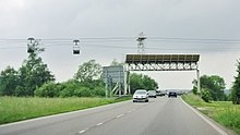
| Protective bridge | Protective bridges have the task of preventing objects from falling onto the traffic route below. They are built under cable cars and during the construction of overhead lines . | |
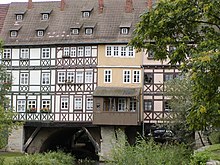
| Residential bridge | In the Middle Ages, some bridges were built which, in addition to the function of leading a traffic route across a body of water, also serve as residential or business premises. Some examples have been preserved, such as the Krämerbrücke in Erfurt or the Ponte Vecchio in Florence , Italy . | |
| Dam | Dams are systems that dam a flowing water . Often a public footpath or a road leads over the dam so that it also serves as a bridge. | |
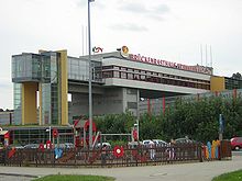
| Bridge restaurant | Many motorway service stations are built as bridges over the motorway lanes. In this way, both directions of traffic can be served with one structure. | |
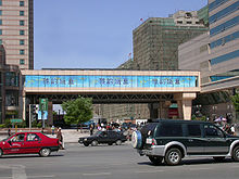
| Skyway | The terms Skyway , Skywalk and Skybridge are used for pedestrian bridges that connect two buildings and belong to the interior of these buildings. | |
| Passenger boarding bridge | A passenger boarding bridge is a technical device that connects the gate with the aircraft, better known in some places as a gangway . |
Classification according to structure
Bridge structures use the three basic types of forces that can appear on mechanical structures: bending , compression and tension . This results in the main groups of bridges: stone arch bridges , girder bridges , arch bridges , suspension bridges and cable-stayed bridges .
Stone arch bridges
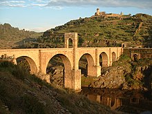
The stone arch bridges have been built for over 2500 years and are sometimes called masonry bridges. The building material was later replaced by structures made of prestressed concrete and steel, which allow larger spans. Today stone bridges are only built for subordinate purposes.
Stone arch bridges can span up to 100 meters. Small spans are mainly used for drainage and are usually designed as culverts made of concrete or other materials. These simple, robust, functional structures have no special architectural properties. Bridges made of precast concrete or steel elements are used for standard applications with a span of up to ten meters. Larger structures are built from reinforced concrete.
Stone bridges can differentiate between different features: the shape of the openings, the type of masonry, the design of the front rim and the shape of the flow dividers in front of and behind the pillars .
Shape of the flow divider
| Design | image |
|---|---|
| triangular | |
| oval | |
| rectangular |
Shape of the openings
| Design | drawing | image | description |
|---|---|---|---|
| Round arch | The opening is in the shape of a perfect semicircle.
The round arch is the most common. This shape was used almost exclusively on Roman bridges . |
||
| Pointed arch |
Pont Saint-Martial in Limoges |
The pointed arch is formed from two circular arcs that intersect at the apex.
This shape is very old but was mainly used in the Middle Ages . It has the advantage that the horizontal forces are reduced, making the arches easier to build, especially for bridges with multiple arches. The disadvantage is the higher overall height compared to a structure with a round arch. This design was rarely used in the German-speaking world, but was often used in Portugal , Spain , France , England and the Arab world . |
|
| Segment arch | In the case of segment arches, the center of the circle is well below the fighter .
This type of construction was developed as early as the 16th century, but it was not until the 18th century, under the influence of Jean-Rodolphe Perronet , that the arches were built really flat and the pillars narrowed so that the water could drain off better. |
||
|
Basket bow , basket handle bow |
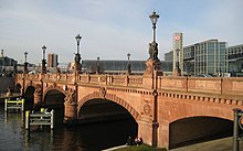
Moltke Bridge Bridge over the Lockwitzbach in Niedersedlitz | The arc is composed of an odd number of circular arcs which lose their curvature towards the apex.
The center points are mirrored in pairs on the perpendicular through the vertex. The outer pair lies on the line through the arched ends, the rest on parallels below. The lowest center point lies on the plumb line, which is why the apex of a basket arch is never at an acute angle. If the pairs of centers are arranged on the evolute of an ellipse, the basket arch approaches them more and more as the number increases. The rule is limited to three or five circular arcs, which reduces the flow cross-section of the river less than elliptical arcs and simplifies the construction. |
Type of forehead wreath
The front rim is the outermost row of stones on the front side of the vault , which forms the transition to the front wall. The two front walls support the filling material of the bridge over the vaults from the sides. The part of the vault that is visible from below is called the reveal.
The front rim can be designed architecturally different. The visible side is usually made flat, but it can also be provided with raised architectural ornamentation. The headbands are more or less representative of the era in which the bridge was built.
| raised in one row | double row | from blocks | two rows flush |
irregular |
|---|---|---|---|---|

|
|

|
|
|
| 1st to 19th century | 2nd to 19th century | 11th to 18th century | 11th to 17th century | 17th to 18th century |

|

|
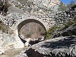
Roman bridge at Estoublon, |

Pont Lesdiguières in Claix |
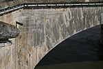
|
Passages
Passages can be seen as a special case of the arch bridge. They differ from the classic stone arch bridges in that the lateral forces are partially dissipated by the backfilling around the actual structure. Diffusers are used in a variety of ways. They are used to cross watercourses such as ditches, brooks and rivers as a wildlife bridge, but also as the smallest form of a railroad or road bridge or as an underpass for pedestrians or cyclists. They can be made of reinforced or unreinforced concrete, steel, stone or, for small cross-sections, made of hard plastic (HDPE). Passages must have a minimal covering of compacted material so that the structure achieves the intended strength for later use. Sometimes the ends are beveled to better follow the shape of the dam and make the passage less visible. The DIN 1076 strictly distinguishes between passage and bridge.
| Design | Graphic representation | image | comment |
|---|---|---|---|
| Concrete passage |
Wildlife Bridge over the Trans-Canada Highway |
Concrete culverts can be either round or arcuate. The latter can either be cast in one piece or consist of an arch on a foundation plate. Round concrete passages usually consist of prefabricated tubes, arched passages can consist of in- situ concrete or also of prefabricated elements. | |
| Metal passage |
Passage on a back road in the USA |
Metal passages usually consist of corrugated iron that is hot-dip galvanized to protect against corrosion . The cross section is either round, elliptical or arcuate. |
Girder bridges
All bridges whose superstructure consists of one or more beams are called girder bridges. Due to their own weight, the beams loaded in bending only exert vertical forces on the abutments and pillars. The bars can be divided according to design and material. The combination of the two properties results in a large number of design options. There are four beam shapes: the beam made of solid material, the hollow box girder or solid wall girder , the truss girder and the Langer beam , which is a combination of a beam and an arched truss. Bridges with Langer beams are usually counted among the arch bridges because the main structure is the arch. The building material used can be metal, non-prestressed reinforced concrete , prestressed concrete , wood or composite material in the true sense of the word, such as carbon fibers .
Integral bridges
Integral bridges are constructions that connect the superstructure to the substructure in a completely monolithic manner. They have neither road transitions (joints) nor supports at the bridge heads of the road girder. With semi-integral types, either joints or supports are avoided, but not both. In the past, such properties were only found in frame bridges and shorter bridges. It was shown that other girder bridges, with and without prestressing, can do without these bridge elements. The calculation of such structural systems is more difficult due to the soil-structure interaction, but their maintenance is easier.
Girder bridges made of non-prestressed reinforced concrete
The reinforced concrete beams, mostly made of solid material, lie lengthways under the roadway and are held together in the transverse direction by the underlying concrete walls, the stems. The beams are usually covered with a reinforced concrete slab, which connects the beams from above and together with them forms the bridge board. The bridge plate can also be made from several prefabricated hollow profile girders or completely without beams. Non-prestressed reinforced concrete bridges are mainly used for shorter spans, such as those required to cross roads or other traffic routes.
| Design | Graphic representation or cross-section |
image | description |
|---|---|---|---|
| Frame bridge |
Small game passage made of prefabricated elements on the A14 |
Frame bridges are often used as passages for pedestrians, game or streams. The abutment walls as well as the front walls hold back the backfilling. Such structures are mostly partially or completely prefabricated and can therefore be erected very quickly. | |
| Two-span frame bridge | The bridge plate is rigidly connected between the posts and the pillars and forms a solid frame with them without abutments and roadway joints, which means that less maintenance is required. | ||
| Full plate bridge |
Full slab bridges consist of a bridge slab made of in-situ concrete, which has a span of 8 to 20 meters and is between half a meter and a full meter thick and is supported on abutments and piers. The surface is usually slightly inclined so that the water can run off. |
||
| Bridge with rib plate |
The ribs of the bridge plate allow a lighter construction of the plate compared to plates without ribs. |
||
| T-beam bridge |
Test track of Aérotrain |
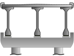
In this type of structure, the deck slab rests on beams, which are often shaped like a I. Due to their height, the beams have great rigidity, so that larger spans can be achieved with this type of construction.
|
Beam bridges made of prestressed concrete
Bridges with beams made of prestressed concrete are used from spans of approximately 30 meters. The following variants are available for the superstructure:
- Rib plate, which is created on a falsework , usable up to a span of about 60 meters
- Prestressed concrete beams with post-tensioning, applicable up to a span of about 60 meters
- Box girder, which is created on site and is pushed over the substructure using the incremental launching method , applicable up to a span of 100 meters
- Box girder, which is created in cantilever construction , can be used up to about 140 meters in exceptional cases up to 300 meters span. With this method, the structure is erected symmetrically from the pillars, whereby the bridge parts called segments are either cast on site or built as prefabricated elements. The stability of the structure even during its construction is achieved by bracing each segment with the existing structure after it has been installed.
| Design | Graphic representation | photo | description |
|---|---|---|---|
| Full-plate or T- beam bridge |
or
|
Bridge over the Canal de Briare |
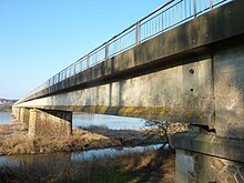
Bridge panels of prestressed concrete bridges can be erected with very low construction heights. Today around a quarter of all road bridges and most highway bridges are built this way. |
| T-beam bridge with post-tensioned single webs |
Bridge at Champtoceaux over the Loire |
The individual beams are pre-tensioned on site in the last step of their assembly. They can be connected by spacers in the transverse direction in order to achieve greater transverse rigidity. The carriageway slab can be completely concreted onto the girders on site or prefabricated slabs are placed, which also serve as formwork for the production of the cover slab . This type of construction is used for spans of 30 to 60 meters. | |
| T-beam bridge with individual webs prestressed ex works | The individual beams are pre-tensioned in the bed during production in the factory and then transported to the construction site. If the beams on the intermediate pillars are not frictionally connected to one another , they are statically determined , otherwise they are statically indeterminate . This type of construction is used for spans of 30 to 50 meters. | ||
| Box girder | The superstructure consists of a trapezoidal or rectangular hollow body with cantilever arms on the sides . Long cantilever arms are often additionally supported on the hollow body by compression struts. The hollow box girder can also have several cavities, so-called cells, and is generally accessible. The height of the hollow box girder can either be constant or taper towards the center of the bridge field, which is referred to as a haunched hollow box girder .
The pre-tensioning is carried out with continuous tensioning cables that either run outside the concrete or are laid in corrugated pipes within the concrete. If the bridge is cantilevered, cantilever cables ensure the strength of the bridge during the construction phase. Starting from the piers, these tendons are placed near the upper deck plate and anchored to the face of the segments that were added last. |
||
| Truss bridge | Truss bridges, like arch bridges, can reach large spans. They are often chosen for aesthetic reasons because they have a small side profile and no vertical lines, which are undesirable in some countries. | ||
| Extradosed bridge |
Twinkle Kisogawa Bridge near Tokyo |
Extradosed bridges are similar in appearance to cable-stayed bridges, with the difference that the pylons are lower. The structure is a prestressed concrete beam, the tensioning cables of which run over the pylons outside the cross-section of the beam. As a result, the beam can be more strongly pre-tensioned and therefore needs a smaller overall height. |
Steel composite bridges
Steel composite bridges have structural parts made of steel as well as those made of reinforced concrete or prestressed concrete. The building materials used are optimally used according to their properties, i.e. concrete is subjected to pressure and steel to tension . The materials are mechanically firmly connected to one another and thus form a unit. This construction method has undergone considerable development since the 1980s, especially the bridges with an open cross-section, which are a cheap solution for spans between 35 and 80 meters. It is also suitable for structures that are in tight arches or that require a particularly low construction height.
| Design | cross-section | photo | description |
|---|---|---|---|
|
WIB bridge
Rolled girder-in-concrete bridge |
Overpass on the Tours - Saint-Nazaire railway line |
The superstructure of these bridges consists of rolled girders that are partially or completely encased with concrete. They have the advantage that they do not require any falsework and can therefore be built with practically no interruption to traffic on the railway line below. Such bridges are used today by many railway administrations. | |
| Double-leg steel composite bridge |
Motorway bridge in France |
These bridges are often used for spans between 25 and 110 meters. The Isteel profiles can either be designed with a full or perforated web, with a constant height or with a haunch. Several bars can also be used for particularly wide superstructures. The bridge slab is made of reinforced concrete and is prestressed in the transverse direction from a width of 13 meters.
|
|
| Composite steel bridge with box girder superstructure |
Railway bridge on the high-speed line LGV Est européenne |
Composite steel bridges with box girder superstructures ensure good load distribution even with one-sided loads. They can withstand large torsional loads that are typically found in arched bridges. The hollow box girder can be designed with one or more cells or be provided with webs and partition walls. Pressure supports can also be attached under the side cantilever arms. |
Steel girder bridges
The steel girders can be arranged either under the roadway or on both sides of the roadway. The first steel bridges used lattice girders , today solid wall girders are mostly used because of the simple production. For particularly light bridges, the bridge deck is designed as an orthotropic plate - a steel construction that is stiffened in the longitudinal direction by welded beads and in the transverse direction by ribs.
| Design | Graphic representation | image | description |
|---|---|---|---|
| T-beam bridge with orthotropic deck slab |
Railway bridge over the Avon |
Particularly light and flexible construction, which however requires considerable calculation effort and careful construction of the details. It is suitable for earthquake prone areas where heavy and rigid structures are unsuitable and in very cold areas where concrete bridges are complicated and costly to build. | |
| Steel box girder bridge with orthotropic deck slab |
Box girders can withstand torsional forces better than solid wall girders. The box girder is provided with stiffeners that prevent the structure from kinking, shearing or twisting too much. Most steel box girders are sealed against the ambient air to prevent corrosion . |
||
| Steel girder bridge with a concrete slab | With this type of construction, the deck slab is not part of the structure because the forces from the deflection of the superstructure are only carried by the steel structure. The concrete deck is not mechanically connected to the steel structure, but only placed on top, which saves the costs of the connecting elements. | ||
| Bollman Girder Bridge | The Bollman girder , patented in 1852, was the first all-iron girder that could be used in the construction of railway bridges. It was used exclusively in the USA and was no longer in use by 1895. The girder consists of an upper chord designed as a frame, which is supported by posts that are braced at the ends of the upper chord. The construction is therefore not a truss , but a trussed girder . | ||
| Lattice girder bridge | Lattice girder bridges are bridges with girders made of a large number of diagonally crossing bars, which are connected to one another at the crossing points. Wrought-iron bridges could be made more cheaply than the first box girder bridges with completely closed surfaces. The technology was used around 1860, but was soon replaced by steel truss bridges. | ||
| Truss bridge | Truss consist of vertical, horizontal and oblique metal bars, between two belts are clamped, the upper chord and the lower chord. The carriers are mostly arranged to the side of the roadway or enclose it in a box-shaped structure. They were widely used in the 19th century, especially for railway bridges. Today, trusses are only used if, for structural reasons, it is not possible to choose a solution with a supporting structure under the roadway. Because truss bridges only require relatively small, lightweight individual parts that are easy to store and transport, they are often used as emergency bridges and are also used by the armed forces . | ||
| Solid wall girder bridge |
Werder railway bridge |
Solid girder bridges consist of two sheet metal longitudinal girders, which are provided with flange plates at the top and bottom and reinforced with ribs. They are often used for functional buildings with no architectural requirements with spans between 20 and 50 m. The roadway can either consist of concrete slabs, steel grids or steel plates that are placed on steel girders. | |
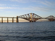
| Cantilever bridge | Cantilever bridges use cantilever beams in the structure. Early designs, such as the Forth Bridge, used trapezoidal tower-like trusses built over river pillars, which were connected with suspension girders . The most common type of construction is the Gerber girder bridge , in which two cantilever girders built from the river banks via a pillar are connected with a suspension girder. With this design, large spans can be achieved in a simple manner. | ||
| Scaffold pier viaduct | In this construction, the individual pillars are constructed as lattice towers tapering upwards with a rectangular cross-section. The distance between the individual pillars is relatively small. They are suitable for overcoming wide, not too deep cuts, as was often necessary when building railways. The largest gantry pier bridge is the more than one and a half kilometer long Lethbridge Viaduct in Canada . | ||
| Truss bridge | Truss bridges can also be built in steel. If there is no slope to support the truss, it can also be doubled to absorb the shear forces, as is the case with the bridge over the great canal in Le Havre . | ||
| Pendulum pier bridge |
Railway bridge in Norway |
With pendulum pier bridges, the piers are articulated to the superstructure and the foundation. They are among the oldest structures that used iron for the pillars, and were initially mainly used in urban areas, where there was too little space for masonry pillars or the height of the bridge was limited. The construction is occasionally still used today for the approach bridges of long suspension bridges. | |
| Box girder bridge | The structure consists of a hollow box that is reinforced by additional beams on the top and bottom. It is a forerunner of today's hollow box girders with the peculiarity that the roadway runs inside the box girder. The construction method was used very early in England for railway bridges. It was soon replaced by cheaper construction methods with lattice girders, later with trusses. |
Wooden bridges
Wood is one of the oldest materials used to build bridges. Wooden bridges can be built from solid wood or from glued laminated timber . The bridge parts can be held together either traditionally with tenon joints or with nails and screws . Different types of wood can be used to build bridges, such as pine , fir , spruce , oak , chestnut and Douglas fir . Depending on the weather, some species are more suitable than others. Pine, for example, is particularly suitable in the maritime climate. For the service life of the bridge, it is important that the structure can dry out or is protected from the weather.
| Design | Side elevation | image | description |
|---|---|---|---|
| Wooden beams |
Footbridge at Vallorcine |
Probably the oldest bridge construction ever: a tree trunk that is laid over a stream. It is still used extensively for very short spans on footpaths or for longer distances when additional pillars can be set. Wood is renewable and available in large quantities. Its great resistance to deflection (only perpendicular to the wood fibers), its lightness and its elasticity have contributed to the frequent use of this building material. | |
| Glulam bridge |
Pont de Keystone Wye |
The glulam beams consist of boards that are glued together with a thermosetting glue and can therefore withstand great mechanical forces. Such supporting structures can be used to create superstructures with spans of up to 40 meters, which have a lower overall height than solid wood structures. |
|
| Covered bridge |
Bridge over the Kleine Emme near Wolhusen |
Most of the covered bridges are timber frame bridges, the supporting structure of which is protected from the weather by cladding and a roof. Although an initial documentation of this construction method can already be found in the four books on architecture by Andrea Palladio , the construction method did not gain acceptance until the end of the 18th century. It was particularly common in wooded areas north of the Alps and in North America. The spans typically range from 20 to 50 meters. Many covered bridges are built as arch bridges or as a combination of girder and arch bridges. | |
| Truss bridge | With the same aesthetics as truss bridges made of concrete or steel, truss bridges can also be built with wood. The truss reduces the length of the cantilever beam so that spans of 20 to 40 meters can be achieved. The example in the picture shows a concrete slab as the roadway. | ||
| Trestle Bridge |
Wilburton Trestle |
Trestle bridges were primarily used in 19th century forestry and in building railways in the Wild West of the United States . They are quick and easy to build. |
Arch bridge
In contrast to stone arch bridges with several arches and pillars, arch bridges made of wood, concrete or steel overcome the river or the abyss with a single arched structure. In the main structure, the arch, only compressive forces occur, which are transferred to the foundations at the ends of the arch, the fighters . They can be built in different materials, the roadway can take different positions in relation to the arch. They are usually erected using cantilever methods .
| feature | Design | cut | image | description |
|---|---|---|---|---|
|
Location of the roadway |
Suspended roadway | The deck is suspended from the arch with the help of hangers . The hangers can be made of cables, metal rods, concrete posts or wooden beams. In the case of network arch bridges, the hangers are inclined, which means that one-sided loads can be better absorbed by the arch. | ||
| Sunken roadway | The roadway is placed halfway up so that it intersects the arch. This results in the lightest variant of the arched bridge, as the length of the hangers and posts is shorter than in the other two variants. | |||
| Elevated roadway | The roadway is on posts above the arch. This variant is particularly suitable for overcoming valleys, because the curve in this variant can be shorter than in the other variants. Furthermore, only in this variant can the arch be arranged over the entire width of the roadway. However, it is only suitable if the high position of the road above the fighters in the terrain is not a disadvantage. | |||
| material | steel | Steel bridges allow a great deal of freedom in the architectural design, as implemented by Santiago Calatrava , for example, for the Pont Bac de Roda . The arch bridges with the largest spans are made of steel. The current record is held by the Chaotianmen-Yangtze Bridge in the People's Republic of China with 552 m. | ||
| Reinforced concrete | Concrete is the most economical material for arch bridges with spans of 35 to 200 meters. The first bridges were built from concrete blocks similar to stone arch bridges. Rammed concrete , reinforced concrete and prestressed concrete were later used, so that ever bolder structures became possible. | |||
| CFST bridge | Only recently are CFST bridges ( English Concrete Filled Steel Tube ) built. Its main structure consists of a tubular steel arch that is filled with concrete and is thus protected from buckling. This construction method is mainly used in China. The first structures date from 1990. They are used for spans from 100 to over 400 meters. | |||
| Wood | Wood is suitable for the construction of arch bridges because of its good properties with regard to pressure loads. Many covered bridges are built as arch bridges, whereby the arch is not visible from the outside. | |||
| Number of joints | Two-hinged bridge |
With a two-hinge bridge, the joints are located at the base of the arch, with a three-hinge bridge they are also in the apex. They allow the bridge to move sideways and vertically, making the structure less rigid. Joints are mainly used in railway bridges and in particular in structures for high-speed lines, where the stresses in the longitudinal direction are particularly great. In concrete bridges, a joint in the apex prevents cracks from occurring when the fighters sit down differently . |
||
| Three-hinged bridge | ||||
| Special cases | Lenticular structure | These bridges consist of two arched supporting structures that face each other and thus resemble the shape of a lens. | ||
|
Langerscher beam
Tied arch bridge |
The two ends of the arch are connected by a beam that absorbs the tensile forces. In contrast to the other arch bridges, this type of construction only transfers vertical forces to the abutments, which is why they are often counted among the girder bridges. Bridges of this type are made in both steel and concrete. They are mostly used as road bridges, railway bridges or as pedestrian bridges. |
Suspension bridge
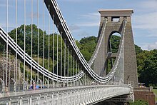
The classic suspension bridges consist of a roadway girder made of steel or concrete, which is suspended by means of hangers on two suspension cables that are guided over two pylons . The hangers are vertical suspension ropes that transfer the load of the track girder to the suspension cables. These parabolic sagging cables transmit a force acting vertically downwards to the pylons, which is then diverted into the subsoil. At the same time, the suspension cables are also subjected to tension, which is absorbed by the anchorages at the ends of the bridge.
In multi-span suspension bridges, the longitudinal forces caused by traffic are carried away by cables that run over the tops of the pylons. These cables do not carry any vertical loads. The vertical hangers can be supplemented by inclined ropes, which reduce the deflection of the pavement beam.
| feature | Design | cut | image | description |
|---|---|---|---|---|
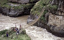
| suspension | Chains | Chain bridges were the first suspension bridges of the industrial age , although older examples are known from the Himalayan region , more precisely from Tibet and Bhutan . The first bridges used forged chains , later they used eye bars , which are movably connected to one another by means of eyes and bolts . They enabled spans that could not be achieved before, such as the Menai Bridge built by the Englishman Thomas Telford , which in 1826 enabled the record span of 176 m at the time. The technology is hardly used today, but there are still some existing structures. | ||
| Rope made of natural fiber | The oldest design of the suspension bridge consisted only of several natural fiber ropes. It could be built with few resources and in a short time, but the structure is very fragile and requires a lot of maintenance. This technique is now only used in remote rural areas for short spans. | |||
| Wire rope |
Wire ropes consist of individual wires that are first twisted into strands, the strands are then twisted into a rope. In technical terminology, this process does not speak of twisting but of hitting . Marc Seguin revolutionized the construction of suspension bridges in the 19th century by using wire ropes instead of chains for the first time. The ropes are much stronger and lighter than chains. The steel suspension cables used today are parallel wire ropes , which are usually provided with a cladding as corrosion protection. |
|||
| Tension band bridge | The superstructure of these bridges usually consists of thin concrete or wooden segments that are placed on the supporting ropes below. Execution is also possible without carrying ropes by connecting the elements directly to one another. These slim bridges require little material and can be erected relatively easily, which results in an inexpensive design. Today it is only used for cycling and walking, as the slack lane is unsuitable for faster traffic. | |||
| Carriageway girders | Concrete slabs with stiffening beams | Concrete slabs connected to stiffening girders are more cost-effective than deck girders made entirely of steel. However, this design is only suitable for medium-span structures. The stiffening beams can either be placed under the roadway or as a parapet. They distribute the load evenly over the hangers of the bridge. | ||
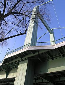
| Orthotropic plate | An orthotropic plate consists of steel plates that are stiffened by longitudinal and transverse profiles. This type of lightweight, torsionally rigid superstructure is typical for suspension bridges and only allows the large spans that are possible today. In Germany, the technology was first used on the Mülheim Bridge, which opened in 1951 . | |||
| anchoring | Anchor blocks in the subsoil |
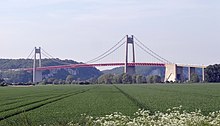
Pont de Tancarville with anchor block |
The anchor blocks of a classic anchoring in the ground must transfer the entire weight of the superstructure, which reaches them in the form of tensile forces via the suspension cables, to the subsoil. The longer and therefore heavier the superstructure, the greater these forces, which is why the anchor blocks are made from heavy materials such as concrete and are buried deep in the subsoil. The subsoil must also be relatively stable in order to be able to absorb the forces. The suspension cables are distributed in the anchor block so that the forces are distributed over the largest possible area. |
|
| Self- anchoring (false suspension bridge) |
In this design, the suspension ropes are anchored to the deck. If they are present, the anchor blocks only absorb vertical forces, while the horizontal forces are diverted into the deck, which must be designed to be heavy and stiff. This solution is used in poor subsoil that cannot absorb the forces of the anchor blocks. The design is also known as a false suspension bridge because the tensile forces are not diverted into the subsoil. |
Cable-stayed bridge
A cable-stayed bridge consists of a girder made of steel or concrete, which is supported by several tensioning cables anchored to pylons . The vertical loads are transmitted to the pylons in the form of tensile forces via the tensioning ropes and are then introduced vertically into the subsoil in the form of compressive forces. The horizontal forces arise on both sides in the direction of the pylon and are absorbed by the deck girder, which is also called the stretch girder.
The cable-stayed bridges differ in the design of the cable field and the bridge girder, as well as the number of pylons and their arrangement.
| feature | Design | Elevation | image | comment |
|---|---|---|---|---|
| Arrangement of the ropes | tufted | In the tufted arrangement, all ropes are anchored at a single knot in the pylon head. The short ropes are practically vertical and hardly hinder horizontal movement of the bridge girder relative to the pylon. In bridges with two pylons, the temperature-related change in length of the bridge girder can be easily controlled with the cluster arrangement; it only has to be ensured that the bridge girder can move freely in the longitudinal direction with at least one pylon. | ||
| fan-shaped |
|
The ropes are arranged in a fan-shaped arrangement in the upper area in several nodes. In this way, the nodes can be formed more easily. | ||
| harp-shaped |
|
In the harp-shaped arrangement, the ropes are parallel to each other. The aesthetically pleasing arrangement shows a mechanically complex behavior. The short ropes prevent longitudinal movement between the pylon and the track girder, so that the latter has to absorb additional horizontal forces.
Slanting pylons einhüftiger constructions remember in a special way to a spar (Engl. Saving ), which harp-like cable-stayed bridges are further sub-divided. |
||
| star-shaped | Looking for a picture of an implementation | This arrangement anchors the stay cables to a large extent point-by-point with the roadway girder and in return distributes the connection points on the hips (pylon) over the height. | ||
| Arrangement of the rope field | central | Some bridges were built with a single centrally positioned rope field. They are usually motorway bridges , where the anchorage of the rope field is in the central reservation of the motorway. Protection against possible damage to the ropes by accident trucks is required. With this design, the roadway girder is usually designed as a hollow box girder because it has to transfer the twisting forces that arise from one-sided loading to the abutments. | ||
| laterally | When arranging two cable fields on both sides of the deck girder, it is sufficient if the pylons on both sides are connected to one another in the foundation. Only with very long cable-stayed bridges is it necessary that the two pylons on each side are connected with a crossbeam. | |||
| Carriageway girders | steel | The steel deck girders of long cable-stayed bridges are usually designed as orthotropic slabs, as is the case with suspension bridges. They weigh only about a fifth of an equivalent concrete structure. | ||
| concrete |
In the case of cable-stayed bridges with two cable levels, the deck girder does not have to be torsion-proof. This allows the use of concrete beams that are cast on site or assembled from prefabricated parts. For small spans, a simple concrete slab is sufficient to which the ropes can be anchored to the side. |
|||
| Number of pylons | a pylon (one -hip construction) |
Some bridges were built with a pylon that is symmetrical to the bridge girder. An asymmetrical construction is more frequently used, the pylon being anchored back in the fore bridge or in an anchor block and part of the vertical forces acting on the bridge girder being absorbed by the abutment opposite the pylon. | ||
| two pylons ( two-hip construction) |
This is the most common type of cable-stayed bridge. The ratio between the span between the pylon and the abutment to the span between the pylons is less than 0.4 in order to avoid that the ropes between the pylons and the abutment can relax in unfavorable cases. | |||
| several pylons | This design allows large valleys such as the Viaduc de Millau in France , straits such as the Rio-Andirrio Bridge in Greece or broad rivers such as the 1600 m long Ganges Bridge with ten pylons to be overcome. Compared to conventional girder bridges, the number of pillar foundations can be reduced, thereby saving costs. |
Classification according to the duration of the transition
Fixed bridges
The structure of a fixed bridge is unchangeable in shape and created for permanent use. Most bridges fall into this category.
Movable bridges
A moving bridge has a structure that can be moved as a whole or in parts. They are mainly used to cross port approaches and canals, where the clearance required for shipping would require an expensive fixed bridge with long access ramps. Provided that road or rail traffic, as well as shipping traffic, is not hindered too much by the temporary interruptions, bridges can be used at such locations whose supporting structure can be moved in such a way that traffic over the bridge girder or the traffic passing underneath is free. They are less expensive than an equivalent fixed bridge.
In individual cases, movable bridges are also used to cross train tracks. Examples are the Grünenwald bascule bridge in Switzerland, which crossed a cogwheel route, or the shovel bridge on the grounds of the Wegberg-Wildenrath test center , which allows access to the test center without the test track having to be interrupted by a level crossing , which increases the speed the test track would degrade.
The drawbridges used in defense construction are also movable bridges. They enable access control by folding up the bridge to make it unusable in the event of imminent danger.
| Design | Side elevation | image | description |
|---|---|---|---|
| Lift bridge | The roadway girder is moved upwards in a horizontal position, thereby clearing the waterway. In contrast to other movable bridges, the clearance height for shipping is limited by the raised deck girder. | ||
| Swing bridge | The deck girder rotates around a vertical axis, mostly a single pillar standing in the water. In order to open the passage for shipping, the deck girder is rotated 90 degrees so that it is parallel to the waterway. | ||
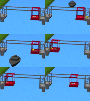
| Transporter bridge |
Transporter bridge under the Rendsburg high bridge |
The bridge girder does not carry the roadway, but a trolley to which a gondola is attached with ropes, in which the traffic can cross. The operation is similar to a ferry . In special cases, the transporter bridge uses the girder of an existing bridge and thus allows traffic to be handled on a further level.
The operation and maintenance of a transporter ferry is expensive, which is why no new such systems are built. The existing facilities are mostly under monument protection. |
|
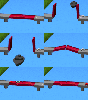
| drawbridge |
Drawbridge in Breukelen |
In this form, a flap rotating around a horizontal axis is pulled up by ropes, chains or rods that attach to the outer end of the bridge flap.
This design is used both in defense structures (see above) and for civil use. The civil applications mostly use two opposing drawbridges and are particularly common in Holland and Belgium. In this design, the flaps are attached to bars, the swing rods, which run parallel over the flap. These have their own axis of rotation above that of the flap and are balanced behind it with counterweights. The bridge can be operated with little effort because only the frictional forces of the hinges and joints have to be overcome. |
|
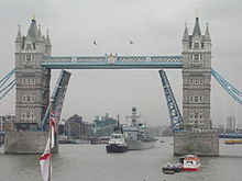
| Bascule bridge | This is similar to the drawbridge. The movable flaps are balanced with counterweights located under the fixed part of the bridge. The bascule bridge is easier to move than the drawbridge, since only the frictional resistance of the horizontal axis has to be overcome. | ||
| Floating bridge | In this design, which is also built as a fixed or temporary bridge, the bridge girder is supported by floating bodies lying in the water. It is possible to swim out part of the bridge girder in order to open the water for navigation. |
Temporary bridges
Temporary bridges are used when the crossing of bodies of water or terrain cuts is only intended for a limited time. They are used by the engineering troops of the armed forces, but also serve civil purposes, such as replacement bridges, during repairs or the construction of an existing bridge. The ice bridges, which only exist in winter, are also among the only temporary bridges.
| Design | image | description |
|---|---|---|
| Temporary bridge | Temporary bridges usually consist of bolted truss constructions, the individual parts of which are transported with normal trucks and can usually even be carried by several people. The parts can be put together like a construction kit to form bridges of various lengths and designs. | |
| Floating bridge |
Pontoon Bridge in Northern Ireland |
Swimming or pontoon bridges are used for both military and civil purposes in places where bodies of water have to be crossed. The individual parts can be transported by truck. They can be erected quickly because they do not need any bridge piers or abutments; only the floating bodies have to be anchored so that they are not driven off by any current. This design was used in Europe to restore river crossings that had been destroyed in the war. |
| Bridge-laying armor | Bridge-laying tanks are used purely for military purposes. At the front, the armored vehicle can move a bridge that is carried over the terrain. The maximum span of the laid bridge is almost 20 meters. | |
| Ice bridge |
Ice bridge in Canada |
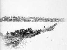
Ice bridges are crossings of frozen rivers that only exist in the cold season. They are still used today in Russia and Canada . Railroad lines were also seldom laid across frozen waters, for example in the early days of the Trans-Siberian Railway a section across Lake Baikal, or the ice trams in Saint Petersburg. If the traffic route runs lengthways along the river, it is called an ice road, not an ice bridge. |
Classification according to size
In addition to many thousands of inconspicuous bridges, there is a much smaller number of structures which, due to their size or other properties, receive special attention and usually also require special maintenance. An example of such a distinction is given here as it is used in the road network of France to distinguish between ordinary bridges and extraordinary bridges . In Germany, bridges over 100 m in length are called large bridges.
| Design | image | description |
|---|---|---|
| Extraordinary bridge | A bridge is considered an extraordinary bridge if at least one of the following properties is met:
|
|
| Ordinary bridges |
Pedestrian bridge in Dresden |
All bridges that do not meet the criteria of the extraordinary bridge are counted as ordinary bridges . |
Classification according to the crossing
| Design | image | description |
|---|---|---|
| viaduct | There is no generally accepted definition of the term viaduct . It is mostly used on railway and road bridges that are longer or higher than would be necessary to cross the actual obstacle. The position of the bridge girder is mostly determined by the route of the traffic route over it. | |
| Viaduct | A valley bridge overcomes a valley and makes it easier for a traffic route to cross it. Railway bridges are called valley bridges in Germany if the bridge deck is higher than 14 m above the terrain. | |
| Slope bridge | Slope bridges, in Switzerland the Lehnen Viaduct , are used to route traffic routes along slopes that are unstable and crossed with the help of the bridge. | |
| River bridge | A bridge that crosses a river . The crossing takes place as perpendicular as possible to the direction of flow of the water in order to save the length of the bridge. The opening of the bridge must be large enough so as not to obstruct the current and ship traffic. | |
| Sea bridge | A bridge that crosses the sea . Sea bridges cross inlets and straits , shortening traffic routes or opening up islands. With these structures, special attention must be paid to the corrosive behavior of salt water and the additional loads of wind and waves during storms, and the needs of shipping must also be taken into account. | |
| Pier , landing stage | A bridge that only crosses the sea in the area of a coastal strip. It can temporarily serve as a jetty . |
Classification according to span
The graphic on the right shows the range of spans in which a particular bridge design can be implemented most cost-effectively. Sometimes, for architectural or technical reasons, designs are chosen that are not in the specified range.
| Design | Side elevation | image | description |
|---|---|---|---|
| Stone arch bridge |
|
Stone arch or masonry bridges are only suitable for short spans. For a long time, the Trezzo Bridge in Italy , which only existed for a short time, was the record holder with 72 m, which was only replaced in 1903 by the Adolphe Bridge in Luxembourg with a span of 85 m. The Danhe Bridge has been in operation in China since 2001 and spans a highway in Shanxi province with a span of 146 m . | |
| Girder bridge |
|
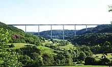
The steel girder bridge with the longest span is the Rio-Niterói Bridge in Brazil , where the central span has a span of 300 m. In France , the record is held by the Pont de Cornouaille near Bénodet . It was opened in 1972 and has a wingspan of 200 m. In Germany, the Zoobrücke in Cologne is the most spanning girder bridge at 259 m. The girder bridges are most economical for spans between 5 and 200 m. | |
| Arch bridge |
|
Arch bridges allow larger spans. They are used today in the range from 200 to 500 meters. The largest arch bridges are in China , which is also the world record holder: the Chaotianmen Yangtze Bridge over the Yangtze with a span of 552 m, which was completed in 2009. (see also list of the largest arch bridges ) | |
| Cable-stayed bridge |

|
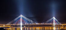
The cable-stayed bridges are particularly suitable for large spans, but are also used for shorter spans. The cable-stayed bridge with the largest span is the Russky Bridge in Vladivostok , Russia . The pillars are 1104 m apart. | |
| Suspension bridge |

|
Japanese Akashi Kaikyō Bridge with 1991 m span. |
Classification according to length
The bridges can also be divided according to the length of the entire structure without taking the number of pillars into account. There are currently over sixty bridges that are longer than 3 km. Most of it is in the People's Republic of China.
literature
- Eugène Degrand, Jean Resal: Ponts en maçonnerie - tome 2 - Construction . Baudry et Cie, Paris 1887.
- Angia Sassi Perino, Giorgio Faraggiana: Les ponts . Gründ, Paris 2004, ISBN 2-7000-2640-3 .
- Les ponts en maçonnerie . Ministère des Transports, Direction des routes, Bagneux 1982.
- Jules Pillet: Traité de stabilité des constructions . Baudry et Cie, Paris 1895, ISBN 2-902170-65-3 ( bibli.ec-lyon.fr/exl-doc [PDF]).
- Anne Bernard-Gély, Jean-Armand Calgaro: Conception des ponts . Presses des Ponts et Chaussées, Paris 1994, ISBN 2-85978-215-X , p. 360 .
- Marcel Prade: Les Ponts, Monuments historiques . Brissaud, Poitiers, ISBN 2-902170-54-8 .
- Marcel Prade: Ponts et Viaducs au XIXe siècle . Brissaud, Poitiers 1988, ISBN 2-902170-59-9 .
- Marcel Prade: Les grands ponts du Monde . Brissaud, Poitiers, ISBN 2-902170-68-8 .
- Marcel Prade: Ponts remarquables d'Europe . Brissaud, Poitiers, ISBN 2-902170-65-3 .
- René Walther, Bernard Houriet, Walmar Isler, Pierre Moïa: Ponts haubanés . Presses Polytechniques Romandes, 1985, ISBN 2-88074-091-6 .
- Charles Abdunur: Arch'01 - Troisième conference internationale sur les ponts en arc . Presses de l'Ecole national, Paris 2001, ISBN 2-85978-347-4 .
Individual evidence
- ↑ Bernard-Gely, Jean-Armand Calgaro: Conception des ponts . 1994, ISBN 2-85978-215-X (French).
- ^ Arch 01. troisieme conference international sur les ponts en arc . Ponts et Chaussees, 2001, ISBN 978-2-85978-347-1 (French).
- ↑ Les ponts en maçonnerie, constitution et stabilité. (PDF; 5.9 MB) In: Publications et logiciels du SETRA. Ministère des Transports, Direction des routes, 1982, accessed February 19, 2013 (French).
- ^ JB Berard: Statique des voûtes . Courcier, Paris 1810, p. 137 ( limited preview in Google Book search).
- ↑ Cadre de PV de visite - buse en béton armé. (PDF; 6.3 MB) Plateforme ouvrages d'art PILES by SETRA, accessed on April 17, 2010 (French).
- ↑ Tuyaux de tôle ondulée. (PDF) (No longer available online.) Ail.ca, archived from the original on May 30, 2009 ; Retrieved April 17, 2010 (French). Info: The archive link was inserted automatically and has not yet been checked. Please check the original and archive link according to the instructions and then remove this notice.
- ^ Cadre de PV de visite - buse métallique. (PDF; 2.7 MB) Plateforme ouvrages d'art PILES by SETRA, accessed on April 17, 2010 (French).
- ^ W. Kaufmann: Integral Bridges. Status report. (No longer available online.) Archived from the original on October 31, 2017 ; accessed on October 31, 2017 .
- ↑ V. Angelmaier, M. Potzl, C.-A. Graubner: Integral Bridges . Ernst & Sohn, 2017, ISBN 978-3-433-03030-1 ( archive.org [PDF]).
- ^ Ponts-dalles, guide de conception . SETRA, Bagneux 1989, p. 7, 31 and 32 (French).
- ↑ Cotation des ponts-dalles en béton armé. (PDF; 527 kB) Plateforme ouvrages d'art PILES by SETRA, accessed on April 11, 2010 (French).
- ↑ Cotation de ponts-dalles en béton précontraint. (PDF; 416 kB) piles.setra.equipement.gouv.fr, accessed on April 10, 2010 (French).
- ↑ Highways Agency, Transport Research Laboratory, SETRA, LCPC (ed.): Ponts en béton précontraint par post-tension . Thomas Telford Publishing, 1999, ISBN 0-7277-2760-5 (French).
- ↑ Recueil de statistiques - Construction des ouvrages d'art - Année 2005. (PDF; 4.1 MB) piles.setra.equipement.gouv.fr, accessed on April 10, 2010 (French).
- ↑ Cotation de viaduc à travées indépendantes à poutres précontraintes par post-tension. (PDF; 1.3 MB) Plateforme ouvrages d'art PILES by SETRA, accessed on April 10, 2010 (French).
- ↑ Cotation pont à poutres précontraintes par fil adhérent. (PDF; 862 kB) Plateforme ouvrages d'art PILES by SETRA, accessed on April 9, 2010 (French).
- ↑ Ponts à poutres préfabriquées précontraintes par adhérence. (PDF) (No longer available online.) Cpcbtp.com, archived from the original on December 14, 2015 ; Retrieved April 9, 2010 (French). Info: The archive link was inserted automatically and has not yet been checked. Please check the original and archive link according to the instructions and then remove this notice.
- ↑ Ponts-routes à poutres préfabriquées par adhérence . SETRA, Bagneux 1996, ISBN 2-11-085784-6 , pp. 5 (French).
- ↑ Cotation poutre caisson en béton précontraint. (PDF; 1.6 MB) Plateforme ouvrages d'art PILES by SETRA, accessed on April 9, 2010 (French).
- ↑ Patrick Losset, DOA du CETE-SO: Ponts en béton précontraint construits par encorbellement - le pont de Layrac. (PDF) Plateforme ouvrages d'art PILES by SETRA, 2006, accessed on April 9, 2010 (French).
- ↑ Anne Bernard-Gely, Jean-Armand Calgaro: Ouvrages d'art - architectural aspect et environnement. (PDF) (No longer available online.) Techniques de l'ingénieur, 1997, archived from the original on April 16, 2014 ; Retrieved April 9, 2010 (French). Info: The archive link was inserted automatically and has not yet been checked. Please check the original and archive link according to the instructions and then remove this notice.
- ↑ Les ponts en béton. (PDF) (No longer available online.) University of Joseph Fourier Grenoble I , archived from the original on October 10, 2010 ; Retrieved April 9, 2010 (French). Info: The archive link was inserted automatically and has not yet been checked. Please check the original and archive link according to the instructions and then remove this notice.
- ↑ Route des Tamarins à la Réunion. (No longer available online.) Archived from the original on February 25, 2010 ; Retrieved April 9, 2010 (French). Info: The archive link was inserted automatically and has not yet been checked. Please check the original and archive link according to the instructions and then remove this notice.
- ↑ Projet de pont: Le viaduc d ́Elle. (PDF) (No longer available online.) Formerly in the original ; Retrieved April 9, 2010 (French). ( Page no longer available , search in web archives )
- ↑ Pnmikti.org - Projet national Mikti, ponts et passerelles de demain. pnmikti.org, accessed April 15, 2010 (French).
- ↑ SETRA: ponts mixtes acier-béton bipoutres . SETRA, Bagneux 1989 (French).
- ↑ RD239 - Suppression of the PN2 and PN3 - Avignon. (PDF; 6.6 MB) piles.setra.equipement.gouv.fr, accessed on April 8, 2010 (French).
- ^ Ponts mixtes acier-béton. (PDF; 1.5 MB) piles.setra.equipement.gouv.fr, accessed on April 8, 2010 (French).
- ↑ a b Guide COMBRI: Pratique actuelle et conception des ponts métalliques et mixtes. (PDF) (No longer available online.) In: Center Technique Industriel de la Construction Métallique. Formerly in the original ; Retrieved April 8, 2010 (French). ( Page no longer available , search in web archives )
- ↑ Les ponts mixtes poutres-caisson. In: Gramme unité construction. Retrieved April 8, 2010 (French).
- ^ Alfred R. Mangus: A Fresh Look at Orthotropic Technology. In: US Department of Transportation, Federal Highway Administration. Retrieved April 8, 2010 .
- ↑ Le viaduc. Retrieved April 8, 2010 (French).
- ↑ Conditions climatiques et l'intérieur des grands corrosion à caissons métalliques. (PDF; 297 kB) piles.setra.equipement.gouv.fr, accessed on April 8, 2010 (French).
- ↑ Internet source Noyan Turkkan: Conception des ponts. (PDF; 2.5 MB) (No longer available online.) In: Cours-genie-civil.com. 2001, archived from the original on April 19, 2009 ; Retrieved April 13, 2010 (French). Info: The archive link was inserted automatically and has not yet been checked. Please check the original and archive link according to the instructions and then remove this notice.
- ^ Wilhelm Ritter: The bridge building in the United States of America: With 12 panels and 60 text figures ... Haller, 1895 ( archive.org ).
- ^ Robert M. Vogel: The Engineering Contributions of Wendel Bollman. In: Smithsonian Institution United States National Museum Bulletin. Smithsonian Press, accessed January 19, 2014 .
- ^ Karl Gotsch: Bollman Truss. Retrieved December 20, 2013 .
- ↑ Petros P. Xanthakos: Theory and Design of Bridges . John Wiley & Sons, 1994, ISBN 978-0-471-57097-4 , pp. 413 ff . ( Google Book in Google Book Search).
- ^ Lethbridge Viaduct. In: Historique et patrimoine du génie civil canadien. Retrieved April 7, 2010 .
- ↑ Le pont Victoria: la 8e merveille du monde. (PDF; 310 kB) (No longer available online.) In: Musée McCord d'histoire canadienne. musee-mccord.qc.ca, 2002, archived from the original on May 14, 2013 ; Retrieved April 6, 2010 (French). Info: The archive link was inserted automatically and has not yet been checked. Please check the original and archive link according to the instructions and then remove this notice.
- ^ Karl Gotsch: Concrete arch bridge. Retrieved April 13, 2013 .
- ^ Thomas Boothby: Designing American Lenticular Truss Bridges 1878-1900. (No longer available online.) Historycooperative.org, archived from the original on October 10, 2008 ; accessed on March 30, 2010 (English).
- ^ Berlin Iron Bridges in Connecticut. (No longer available online.) In: Public Archeology Survey Team, Inc. Archived from the original on July 5, 2010 ; accessed on March 30, 2010 (English). Info: The archive link was inserted automatically and has not yet been checked. Please check the original and archive link according to the instructions and then remove this notice.
- ↑ SETRA: Instruction technique du 19 October 1979 pour la surveillance et l'entretien des ouvrages d'art - fascicule 34 - Ponts suspendus et ponts à haubans . SETRA, Bagneux 1979, p. 7 (French).
- ^ Conception & dimensionnement des ponts en acier. polytechpress.com, accessed March 27, 2010 (French).
- ^ Peters, Tom F .: Transitions in Engineering: Guillaume Henri Dufour and the Early 19th Century Cable Suspension Bridges . Birkhauser, Basel 1987, ISBN 3-7643-1929-1 ( books.google.com ).
- ^ Les ponts suspendus, l'invention. art-et-histoire.com, accessed on March 28, 2010 (French).
- ↑ Technique cables acier. (PDF) fatzer.com, accessed on September 7, 2013 (French).
- ↑ Jiri Strasky: Stress-ribbon pedestrian bridges supported or suspended on arches. (PDF) (No longer available online.) Arch-bridges.cn, 2008, archived from the original on December 14, 2013 ; accessed on March 29, 2010 (English). Info: The archive link was inserted automatically and has not yet been checked. Please check the original and archive link according to the instructions and then remove this notice.
- ^ Leonhardt, Fritz (1909-1999). (No longer available online.) In: great-engineers.de. Brandenburg University of Technology Cottbus , archived from the original on September 22, 2013 ; Retrieved September 13, 2013 . Info: The archive link was inserted automatically and has not yet been checked. Please check the original and archive link according to the instructions and then remove this notice.
- ^ Les solutions aux contraintes. (No longer available online.) Zebac.free.fr, formerly in the original ; Retrieved March 27, 2010 (French). ( Page no longer available , search in web archives )
- ↑ Les ponts suspendus classiques. ponts-suspendus.chez-alice.fr, accessed on March 27, 2010 (French).
- ↑ Le grand pont sur la Loire. fr.structurae.de, accessed on March 27, 2010 (French).
- ↑ Revue de presse Baudin Chateauneuf 2008. (PDF) (No longer available online.) Le Moniteur, March 28, 2008, pp. 11, 12 and 13 , formerly in the original ; Retrieved March 27, 2010 (French). ( Page no longer available , search in web archives )
- ↑ Instruction technique du 19 October 1979 pour la surveillance et l'entretien des ouvrages d'art - fascicule 34 - Ponts suspendus et ponts à haubans . SETRA, Bagneux 1979, p. 26 .
- ↑ a b c d René Walther, Bernard Houriet, Walmar Isler, Pierre Moïa: Ponts haubanés . Presses Polytechniques Romandes, 1985, ISBN 2-88074-091-6 .
- ↑ a b c d e f Anne Bernard-Gély, Jean-Armand Calgaro: Conception des ponts , 1994.
- ↑ Sven Ewert: Bridges - The development of spans and systems . Ernst & Sohn, Berlin 2003, ISBN 3-433-01612-7 , pp. 155 .
- ↑ The Trans-Siberian Express. Retrieved September 8, 2013 .
- ↑ The Eisstrassenbahnen in Saint Petersburg. Retrieved September 8, 2013 .
- ↑ Circulaire n ° 94-56 from May 5, 1994 définissant les modalités d'élaboration, d'instruction et d'approbation des opérations d'investissements sur le réseau routier national non concédé. (PDF) In: Portail documentaire du SETRA. Retrieved February 16, 2010 .
- ^ Rolf H. Pfeifer, Tristan M. Mölter: Handbuch Eisenbahnbrücken . DVV Media Group, Hamburg 2008, ISBN 978-3-7771-0378-5 , p. 60.
- ↑ Charles Abdunur: ARCH'01 - 3rd Conference on arch bridges. Presses de l'École nationale des ponts et chaussées, Paris 2001, ISBN 2-85978-347-4 , pp. 667-670.
- ↑ Danhe Bridge. In: HighestBridges.com. Retrieved August 25, 2020 (with pictures).
- ↑ Rio-Niterói Bridge. In: Structurae
- ↑ Jean-Pierre Ducout: Ponts métalliques - Conception générale
- ^ Serge Montens: Les plus beaux ponts de France , Benneton, 2001.


