
Rail (rail transport)

.jpg)
Rails are Bahnwesen linear bearing and guide elements, which are usually in pairs and parallel to one another in the spacing of the track width of the travel path for arranged rail vehicles form.
Early rails in this sense were ruts, tree trunks laid out lengthways or wooden planks. Modern rails are standardized and standardized rolled steel products . They are mostly in regular, short intervals to transversely laid out to the track axis sleepers of concrete , steel , wood or plastic attached and form a track together with the hardware (which are the fixing parts of the rail on the threshold) and the bedding the superstructure of a railway line .
Beginnings

In order to improve the driving characteristics of horse carts on bad ground, "rail systems" made of wood were developed as early as the 17th century. These wooden rails prevented the wagon wheels from sinking in and thus enabled heavy loads to be transported regardless of the nature of the ground. Unfortunately, these wooden rails did not prove to be very durable, so the search for other suitable materials began. New rail systems were developed in England during industrialization with its burgeoning iron and steel production. The first iron rails for railways were comparatively thin sheet metal strips that were nailed to "road trees" parallel to the direction of travel in order to increase stability and reduce wear.
In 1767 Richard Reynolds , one of the owners of the Coalbrookdale ironworks, had cast iron ingots in plate form in stock as a result of sales problems . In order to be able to use these meaningfully in the meantime, he had worn wooden plank rails of the hut railway laid out with them, where they served the intended purpose excellently. This is seen as the birth of iron rails for vehicle wheels.
Profiles
Historical profiles
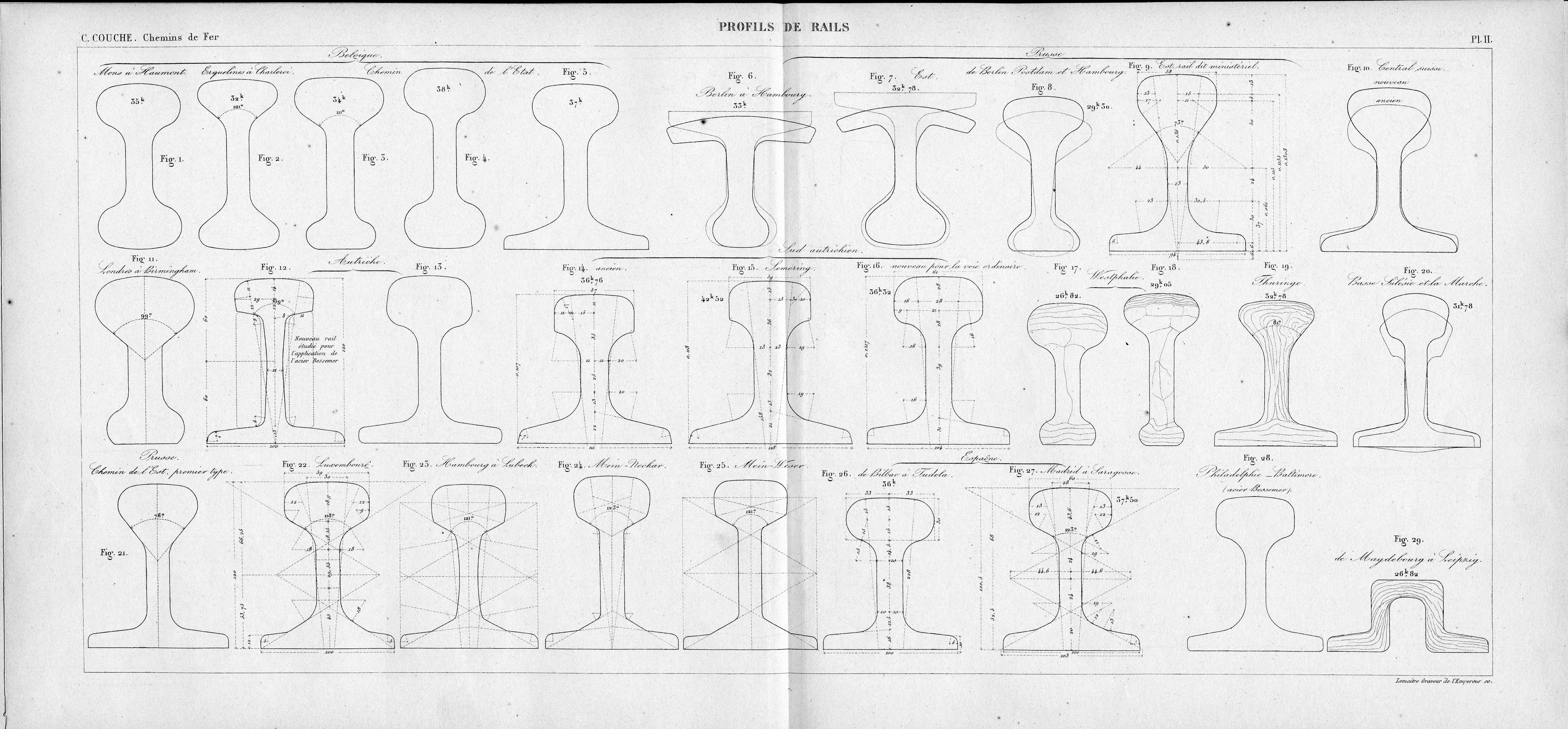
Charles Couche (1815–1879), Inspector General, Author and Professor of Construction and Railway Engineering at the National School of Mining, has compiled an overview of the international rail profiles in one of his many treatises on technical innovations.
Fish belly splint

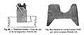
Profile of the wedge head rail

Double head rail (2),
1 = wheel tire with flange,
3 = rail chair,
4 = wooden sleeper
Double head rails in rail chairs were among the first iron rail systems.

Cross-section of a Barlow rail, formerly used by the Sydney Railway Company

Haarmann's sleeper rail, cross-sectional drawing

historical rail profiles of the Leipzig tram


Angle rail

John Curr resulted in 1776 in the coal mines in the coal mines of Sheffield angle rails one. These first rails had the advantage that vehicles with normal wheels could run on them and were not dependent on the rail guide alone. In the first years of the 20th century, the historical use of angle rails ended. With the use of track vehicles with pneumatic tires , it has now experienced a locally limited renaissance: The wagons of the Poma 2000 automatic funicular railway in Laon , northern France, set up in 1989, ran on L-profiles, they were held on these rails by their laterally protruding edges.
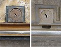
Mushroom rail
One of the oldest steel rail forms at all consisted only of the thickened rail head with the running surface and a vertical web for stiffening and fastening. The fastening consisted of clamping in specially shaped stone blocks. So it is a sub-shape of the chair rail . Because of their cross-sectional shape, these rails were also called head-and-web rails or mushroom rails . The vertical bar offered only little resistance to deflection, so that in the course of development a thickening was also attached to the underside of the rail. This development initially led to the double-head rail described below and later, after systematic tests, to the Vignole rail, which is still in use today.
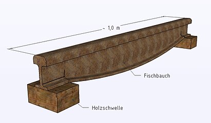
Fish belly splint
Because of the relatively light vehicles, early railroad tracks had far fewer support points than they do today. The usual distances between bases were about one meter. On the other hand, since it was not yet possible to roll long rail profiles, cast iron rails one meter in length were often used. This means that these rails only rested at both ends. With increasing axle loads, this led to ever greater deflections of the mushroom rails that had been used up until then, which led to uneven running of the vehicle and increased wear and tear.

Based on the principle of the fish-belly girder used in bridge building , the fish-belly splint was developed by William Jessop around 1789 . It is about a yard (approx. 91 cm) long piece of rail, the height of which increases steadily on the underside from the ends towards the middle, whereby a higher bending resistance moment is achieved. However, the material consumption for fish belly splints is relatively high; they also cannot be rolled continuously. With the introduction of shorter support points and the possibility of rolling longer pieces of rail, this historical rail shape was abandoned.
Wedge head rail

Wedge head rails are very similar to Vignole rails. In contrast to these, the flanks of the rail heads are bevelled in a wedge or trapezoidal shape, so that the cross-section of the rail head decreases towards the bottom. Wedge head rails are mainly used in mountain railways. They are used as running rails, for example, on the Reichenbachfallbahn in Meiringen , which have an additional caliper brake , the brake shoes of which grip the rail head on both sides and cling to the rail so that they cannot be lost. Wedge head rails were in use at the Pöstlingbergbahn in Linz until they were replaced in 2009. Racks from the Strub system are milled from wedge head rails with a raised head.
Double head rail

Built-in rails are only hit by the wheelsets on the inside, i.e. they are worn on one side. To increase the service life, the rails are rotated on tracks with little traffic or they are exchanged for one another so that the still intact outer edge of the rail now lies on the inside. With the double-head rail, the service life of the rail was to be further increased by using a symmetrical profile with a rail head each on the top and bottom and attached by means of rail chairs. This gave four installation options, in which the two rail heads were used one after the other as a running surface and the rails were also swapped for one another using the method described. However, experience has shown that the rails with the material at that time were already brittle before they could be rotated for multiple use.
Variants of the double-head rail were later developed, which could no longer be turned because the head was flattened on one side, but could still be installed in the existing rail chairs for double-head rails. These rails, known in English as Bull Head Rail , were the standard rails in Great Britain well into the 20th century, they are still in use on low-traffic routes in Great Britain, Ireland and France and even on sections of the London Underground .
Bridge, Brunel and Barlow rails
In 1835, Strickland invented the bridge rail with a cross-section similar to a hat cut vertically. It was mostly laid on long sleepers, later also called the Brunel rail after the engineer Isambard Kingdom Brunel , who used it on a large scale on the Great Western Railway in 1836 .
A further developed form was designed by William Henry Barlow in 1849 - the rolled Barlow rail with a hat-shaped cross-section, but a considerably reinforced running surface. It was also a saddle rail that was laid directly in the bedding without sleepers. Seaton created a saddle rail in 1856 that was mounted on a triangular wooden long sleeper.
Haarmann's sleeper rail
August Haarmann developed a concept of a longitudinally symmetrical two-part rail profile with T-bars attached underneath transversely to the longitudinal direction. The longitudinal division was intended to enable the rail vehicles to run more smoothly at the rail joints by slightly overlapping assembly. The twin and triple rails , which are composed of two to three individual profiles and were used in tram networks before the introduction of one-piece rolled grooved rails , also come from Haarmann .
Development towards the standard profiles
In the second half of the 19th century, the cross-section that is common today, with a reinforced head and a broad base, prevailed for most railways. Initially, the mostly private railway companies procured rails according to their own dimensions, which were hardly interchangeable with the rails of the neighboring railways. In an overview table from 1871, 50 rail variants of various dimensions and material qualities are listed for the German railways alone. At that time, the track lengths were mostly between 6.00 and 7.00 m.
After the importance of the railways as a means of military transport was recognized, the first requirements for standardization were drawn up. At the same time, nationalization efforts began in Germany in order to gain control over the railways. The standard rail profile introduced by the Lower Silesian-Märkische Eisenbahn in 1867 with a weight per meter of 36.96 kg / m was introduced to other railways that were under Prussian influence.
The concentration processes continued after the founding of the Empire in 1871 and especially after the founders' crash in 1873. The rail profiles were standardized according to load classes at the larger railway companies and gradually reinforced. The table shows a selection of the development of Prussian standard profiles from 1868 to the standard profile of the Deutsche Reichsbahn S 49 in the 1920s.
| designation | Mass kg / m |
Height mm |
Head width mm |
Web width mm |
Foot width mm |
Remarks |
|---|---|---|---|---|---|---|
| Prussia. Shape 5 | 24.39 | 115 | 53 | 10 | 90 | |
| Prussia. Shape 6 | 33.40 | 134 | 58 | 11th | 105 | |
| NME form 7 | 36.96 | 131 | 58 | 14th | 102 | Standard profile of the Niederschl.- Märk.-Eisenbahn from 1867 |
| Prussia. Shape 7 | 37.24 | 134 | 58 | 18th | 105 | Special profile for bridges |
| Prussia. Shape 8 | 41.38 41.00 |
138 | 72 | 14th | 110 | |
| Prussia. Form 9 | 43.43 | 138 | 72 | 18th | 110 | Special profile for bridges |
| Prussia. Form 15 | 45.05 | 144 | 72 | 14th | 110 | |
| Prussia. Form 16 | 47.28 | 144 | 72 | 18th | 110 | Special profile for bridges |
| P 45 | 45.25 | 142 | 67 | 14th | 125 | |
| P 49 | 49.05 | 149 | 67 | 14th | 125 | Standard profile of the DRG |
The material quality was improved by using Bessemer or Martin steel . In addition, the rail length has been increased several times to standard lengths such as 9, 12 or 15 m in order to reduce the number of rail joints.
Rail inclination
In order to adapt to the running surfaces of the wheels, which are conical for self-centering in the track, the rails in the track are usually inclined towards the center of the track. This inclination is worked into either the production boards or the sleepers. In the past, the European standard of this inclination, adapted to long-axis two- and three-axle vehicles, was 1:20. In bogie vehicles, a smaller taper of the wheel running surfaces has proven to be more favorable for wear and smoothness. Due to their increasing share in the vehicle population, the regular slope of the rails has been reduced to 1:40 since the 1960s, at the same time as the introduction of heavy rail profiles. Track types with concrete sleepers or rails heavier than S 49 were usually developed from the outset with an incline of 1:40. In Germany, tracks with 1:20 inclined rails can only be found in side tracks and on branch lines with low loads and long periods in which the superstructure is in place.
Some tram networks have vertical rails and cylindrical wheel tires. At the time of construction, it was believed that the self-centering due to the sinusoidal motion was hardly effective anyway due to the small track clearance and the narrow arc radii. A well-known example of vertical rails and cylindrical wheel tires is the network of the Berlin U-Bahn . In operation, however, a conical wear profile occurs.
In switches and crossings and on short pieces of track up to 40 meters between switches, the rails are vertical, especially to simplify the construction and to avoid multiple changes in inclination. In some newer turnout constructions, the inclination is incorporated into the running surface of the rails. Between tracks with vertical and 1:20 inclined rails, transition sleepers are installed with an inclination of 1:40.
Today's rail types
Standard profiles


In the area of Deutsche Bahn AG, three rail profiles are generally used today. With a mass per meter of 49 kg / m, the S 49 profile is the lightest. It was the standard profile of the Deutsche Reichsbahn and its successors from 1922 to 1963. It is still available on many lines, but is only installed for less loaded tracks. This profile is also used for narrow-gauge railways , in street and subway networks. The standard profile S 54 with 54 kg / m can be found on main lines and station tracks . It was created by reinforcing the S 49 profile, especially with regard to the height of the rail head and the thickness of the rail base, and was the standard profile of the Deutsche Bundesbahn from 1963 . Both profiles have the same foot width at 125 millimeters and are therefore largely interchangeable with one another. The UIC 60 profile weighs 60 kg / m and has generally been used for heavily loaded routes since 1970, both for high axle and tensile loads and for high speeds. The foot width of this profile is 150 millimeters. Another profile standardized by the UIC, UIC 54, is comparable to the German profile S 54 and is mainly used in other European countries (e.g. in Spain and the Netherlands). This profile has a foot width of 140 millimeters, so it requires special pads or rail mounts.
| designation | Mass kg / m |
Height mm |
Head width mm |
Web width mm |
Foot width mm |
Remarks |
|---|---|---|---|---|---|---|
| P 49 | 49.05 | 149 | 67 | 14th | 125 | Standard profile of the DRG |
| P. 54 | 54.54 | 154 | 67 | 16 | 125 | from 1963 standard profile of the DB |
| UIC 54 | 54.77 | 159 | 70 | 16 | 140 | |
| UIC 60 | 60.34 | 172 | 72 | 16.5 | 150 | from 1970 for heavily used routes |
| R 65 | 64.64 | 180 | 75 | 18th | 150 | for high loads in the GDR |
In the network of the Deutsche Reichsbahn in the GDR , the Soviet R 65 profile with 65 kg / m was installed for high loads. Thanks to the foot width of 150 millimeters, the UIC 60 and R 65 profiles are also interchangeable on the horizontal track. The R 50 profile, comparable to the German S 49, was mainly used in tram networks, but also, for example, on the Windbergbahn to Dresden-Gittersee. For narrow-gauge lines, the S 33 profile was rolled for the last time with 33 kg / m in the 1960s. Profile S 41, which corresponds to a rail S 49 with a reduced head height, is still common in subway networks. In side tracks and connections there are also rail profiles such as form 8 from the era of the regional railways.
In the USA , the 140-RE (70 kg / m) profile is installed for heavily used routes.

When changing the rail profile in the track, transition rails produced industrially by flash butt welding are installed , especially in the case of conversions . When changing rails as part of maintenance and if transition rails are not available, for example between R 65 and UIC 60, the different profiles must be connected with aluminothermic transition welds . If this is not possible due to a lack of space, for example in crossovers or because there are no corresponding welding forms, the rail ends must be connected by manual arc welding . Arc welding is the standard procedure in many tram networks. Kropf and transition straps are only permitted in construction stages and for temporarily securing broken rails. If the profiles to be connected are too geometrically different, several transition rails or welds must be provided one behind the other.
If possible, the same rail profile is used for turnouts as for the adjacent tracks, and if the two lines are subjected to different loads, that of the more heavily loaded one. The switch blades on switches of German design are made from special, asymmetrical switch rail profiles with a reduced height.
Vignole rail or broad foot rail


.JPG)
Ultimately, the broad-footed splint developed by the American Robert Livingston Stevens around 1830 prevailed, which was later improved by the Englishman Charles Vignoles , after whom it is named. It consists of a wide, flat base with which it is usually attached to sleepers with tension clamps . On top of it stands a narrow web that carries the rail head at its upper end, which in turn forms the track for the wheels. The UIC 60 rail profile is predominantly used today in the area of Deutsche Bahn. It differs from older designs in that it has a more curved running surface and a higher web.
In order to avoid mix-ups and incorrect use, a defined identification with letters and numbers is rolled into the web of the rail profile. The current EU standard for this rolling mark as of 2014 is DIN EN 13674-1: 2011-04 (D). Older forms of labeling were partly purely manufacturer-specific .
The Vignole rail is fastened to the sleepers mostly with the interposition of a base plate or ribbed plate, which on the one hand supports the rail foot and guides it laterally, as well as providing the bores and recesses for the fastening screws or spring elements towards the sleeper . In the past and under simple conditions, the supports for the Hs superstructure were simply planed into the surface of wooden sleepers and the rails were fastened with sleeper screws. Advances in concrete production made it possible to dispense with production plates for the W superstructure .
Crane rail
A second variant of the Vignole rail is the crane rail. There are different types of crane rails:
Form A and F according to DIN 536: these are lower compared to the rails used on railways and have a thicker web to withstand the heavier loads. They are usually mounted on a continuous further support, especially a steel base, which is referred to as "continuous storage".
Vignole rails are used in exceptional cases as crane rails and are often mounted on rail chairs or sleepers, which is referred to as "discontinuous storage". Discontinuous storage is considered to be very susceptible to damage here.
Heavy special profiles, mainly with the designation MRS, are not standardized and are used for high loads. There is now a "modern variant": the AS 86 rail. It was further developed from an MRS 87a profile (with a flat wheel running surface) so that the rounded head, analogous to Form A, shifts the force transmission as far as possible to the center of the head.
Grooved rail
Description and use


.jpg)
The grooved rail is mostly a rolled steel profile that is used in particular to build tracks for trams. It differs from the Vignol rail by the groove rolled into the head. The groove always ensures a free track channel in which the wheel flange rolls. Differences in height of the road surface or the pavement are kept away from the wheel flange. In contrast to Vignole rails, grooved rails sometimes get by without a ballast bed and without sleepers, in this case they are placed on a solid concrete base and anchored in this. For a larger support surface in these cases, grooved rails have a wider rail foot than comparable Vignole rails; 180 millimeters are common. A special form of the grooved rail superstructure is the so-called large composite slab, which is prefabricated track sections with road surface that only need to be used on site.
The rail vehicle is guided by the contact between the flange and the rail head; the outer edge of the groove essentially only serves to protect against unintentional narrowing. This is especially important when the covered grooved rail track is run over by road vehicles. In tight bends, wear and tear also results in a rear surface guide on the inside of the bend after a while. To increase the length of stay, rails with reinforced grooves are therefore laid in such arches. Basically, grooved rails are selected according to the application. In most tram networks, due to historical developments, narrower wheel flanges and wheel tires are used; grooved tram rails adapted to them have a groove width of around 40 millimeters. In railway networks, wider wheel flanges and wheel tires are used; in grooved rail tracks, the groove width is around 60 millimeters.
For drainage of surface water, grooved rails that are built into the road surface have drainage openings and water boxes at regular intervals. The openings are only created after the rail has been installed. The cleaning of other dirt or sand from the track channel used to be done by unskilled workers , the so-called Ritzenschiebern . Today this is done mechanically with rail cleaning vehicles .
In the past, it was also common practice for many tram operators to install grooved rails on the open sleeper superstructure. The reasons for this were, on the one hand, the geometry of the driving edge, which is usually better adapted to the tram wheel tire profile with a smaller radius of curvature between the tread and the flange flank, and, on the other hand, the waiver of the complex transition welds between grooved and vignole rails due to the different height and position of the rail web. Grooved rail superstructure in arches that was not covered lasted for a particularly long time. It was assumed that the wear-related rear surface guidance on the inside rail, comparable to guard rails on railroads, would improve the running safety. However, this assumption was not confirmed, apart from very tight curves, for example in turning loops .
In addition, some transport companies also set up short grooved rail sections on pure Vignole rail routes. These are only a few meters long and are usually next to a street. They enable two-way vehicles to be tracked in for rescue or maintenance purposes so that they can reach their destination away from the roads by rail from there. Alternatively, level crossings can be used for railing on and off. To avoid profile changes, however, there are also additional profiles for Vignole rails that are screwed to these sections or suitably profiled concrete or rubber elements.
benefits
Grooved rails are sometimes installed and covered in areas where there is usually no individual traffic on the track. However, in an emergency this can be used by rescue vehicles, which can be particularly advantageous in the case of tunnels. Furthermore, a rail replacement service with buses can be set up more easily on such sections , and wrecked rail vehicles can also be towed there by road vehicles. In the same way, grooved rail sections can also be cleared of snow with road vehicles, and vegetation control , i.e. weed killing with chemicals , is no longer necessary .
disadvantage

In general, with grooved rails there is an increased risk of derailment compared to Vignole rails due to potential foreign bodies in the groove . Another major disadvantage is the risk of falling for cyclists, especially if the rails have to be crossed at an acute angle or are wet. For this reason, disused grooved rail sections are often temporarily filled with rubber or cement until the rails can be removed years later.
Furthermore, grooved rails are also worn out by road traffic. In addition, the installation in the road surface promotes corrosion of both the rail profile and the fasteners through penetrating surface water. Covered grooved rails must therefore be replaced more frequently than Vignole rails. This, in turn, is always associated with hindrances for road traffic and, after the completion of the track construction work, also requires the restoration of the road surface.
In winter, heavy snowfall can quickly clog the grooves from precipitation. This is especially true if the snow is pushed into the groove by other road users and is also compressed there. Sections flush with the road therefore often have to be kept clear in winter by so-called lane drives , especially during the night-time break in operations, while sections of the road that are not covered only have to be cleared when the snow depths are significantly greater.
Since grooved rails pose a danger to cyclists, there are rails with rubber fillings to prevent cyclists from falling into the groove and falling. They will be tested by the Basler Verkehrs-Betriebe until the end of 2022. However, they cannot be used by some rail vehicles that are too light to press the rubber into the groove.
story
After the world's first tram operated in New York as early as 1832, the problem arose that the rail heads of the Vignol rails protruded from the roadway and hindered other road users. For the first tram in Europe, the Paris tram , the engineer Alphonse Loubat applied for a patent in 1852 for U-shaped rails sunk into the roadway, which could be nailed to longitudinal beams and built into the roadway without protruding. George Broca , director of Tramways du Nord in Paris, invented and patented a steel grooved tram rail with a flat base in 1876 , which could be manufactured in rolling mills.
Before the invention of the grooved rail as a single profile, two vignole rails with lining pieces were often screwed next to each other (Haarmann rail, comparable to the Lindau type still used for crossings), or a special angle profile (groove rail) was screwed to the side of a vignole rail. This procedure is still used in some cases today. Such profiles are still rolled for rails S 49 and S 54.
The first one-piece grooved rails were rolled in 1880 at Phönix AG in Ruhrort for the city of Plymouth's trams . Due to the inept formulation of the Phönix patent , other German steelworks, such as the Gesellschaft für Stahlindustrie in Bochum in 1884 and the Hörder Verein in 1887, began production using slightly modified rolling processes. It was only after 1900 that foreign rolling mills succeeded in producing Vignol grooved rails. This rail profile was also called the Phoenix rail after the original manufacturer .
Early grooved rail based on the Loubat system

Cross-section of a grooved rail of the Berliner Verkehrsbetriebe

Tram track with grooved rails on concrete substrate during renovation work
Device for draining a grooved rail, on the left under construction, on the right when installed

Warning notice to cyclists in Nottingham


Track rails for rail systems with pneumatic tires

The use of vehicles with pneumatic tires partly led to new types of track systems with likewise new types of guidance and track changing systems.
Single track rails
Saddle railways use concrete beams with lateral and central track guidance as the route. For the lateral track guidance, vertically mounted flat steel strips are sufficient, which transfer the track guidance forces to horizontal guide rollers attached to the side of the vehicle. If the lateral track guidance is not also used for the energy supply, wooden and concrete beams can also be used for this.
The less common system of central lane guidance is used for vehicles that also participate in general road traffic (e.g. Tramway de Nancy ). In this case, a groove is milled in the road surface, into which specially shaped (mostly U-shaped) rails are inserted, into which the vehicle's guide pin engages. The guide rail is constructed in a similar way on guardrail tracks such as Translohr or Neoval , but its head has a hexagonal cross-section and the two guide wheels inclined by about 45 ° laterally enclose this rail head. In the original Véhicule automatique léger system , the double guardrails in this case are only available in the switch area. Otherwise, the trolleys are guided through the vertical guide rails on both sides, which are also used as power rails and are therefore suspended in an isolated manner.
Suspended gondola lifts such as the Wuppertal suspension railway mostly use steel rails on which the wheels run, the rails in turn are suspended from supporting frames or concrete beams.
Manufacturing
From cast iron to steel
From 1770 cast iron rails were laid on stone blocks, for the first time on the Derby Canal Railway in England. The Englishman Ralph Allen invented the one-sided wheel flange in the 1730s, which guides the wagons safely on the track. According to other sources, the wheel flange was not introduced until 1789.
With the introduction of the flange wheels, rails with a mushroom-shaped cross-section with and without a lower reinforcement of the web were used. The short, cast-iron rails could only form a very poor track, unsuitable for larger wheel pressures (as required by the locomotives in the making). In 1820, John Berkinshaw in Durham succeeded in producing rails by rolling, thus making them from more durable material and in great lengths (15 feet at the time).
“The cross-sectional shape initially remained the same mushroom shape and the support also remained the same with cast-iron rail chairs on stone cubes. Strangely enough, it was believed not to be allowed to deviate from the fish-belly shape in the longitudinal direction and rolled the corrugated rail with great effort. These rolled rails were first laid on part of the small Stocton-Darlington [sic!] Railway (1825) and on the first large locomotive railway, Liverpool-Manchester (1826–1830). ”(Meyers Konversationslexikon, 1905)
In the middle of the 19th century, the transition to the much longer-lasting steel rails took place. For example, the forerunners of VÖEST from 1850 supplied the first rail heads made of welded iron , from 1857 Robert Forester Mushet supplied the first steel rails ( Bessemer process ), from 1862 Alfred Krupp steel rails (Bessemer process) and from 1869 forerunners of voestalpine first rails made of SM steel ( Siemens-Martin process) ).
Rail production today
Railroad tracks are rolled from high quality steel, which requires around ten rolling passes. If necessary, the splints are then subjected to a hardening of the head . This consists of quenching from the rolling heat by immersion in a hardening bath or inductive heating and subsequent compressed air cooling of the rail head. After rolling, the rails are cooled uniformly and in a controlled manner as a whole in a correspondingly long cooling bed; The resulting deviations from the straight course are eliminated by cold straightening on a roller straightening machine under high pressure, also known as "ironing" in technical jargon.
This is followed by the quality control of each individual rail; it is checked for straightness, correct surface and internal condition. The high initial quality of the steel used enables the scrap material to be recycled directly. In the final processing, the sawing to the desired length and possibly also the drilling of so-called " tab holes " takes place. Just in time (JIT) delivery to the relevant construction site is customary .

Long rails for rail transport are either manufactured with a length of 120 meters or welded in the factory from two to four sections to form long rails. Further welds up to 360 m or even 500 m pieces are possible. In the case of deliveries by ship overseas, the rail length is limited to 60 meters. Long rail logistics require long special wagons ("long rail units") and several cranes working in parallel . It is advantageous to minimize the expensive welding work on site in the construction track using the thermite welding process or the flash butt welding process and the maintenance effort required for the seams (so-called " rail joints "). 30 m long rails were common on the Deutsche Reichsbahn from 1928, and around 1930 60 m long rails were also being tested.
Rails for tight curve radii (e.g. less than 300 m or as switch parts) that cannot be laid in the curve on site are pre-bent in the factory on a three-roll machine.
In the past, railroad tracks were a standard product of almost all rolling mills , but the quality requirements are now so high that there are only a few specialized rail mills left . High steel quality, low rolling tolerances and eddy current surface testing of all rails have become a matter of course. The largest rail rolling mill in Europe (in Donawitz , Austria ) belongs to Voestalpine . The last remaining producer in Germany, TSTG Schienen Technik , also belonged to Voestalpine AG and was closed at the end of 2013. Until 2011, there was a price cartel on the German market that referred to itself as " Eisenbahnfreunde ".
Manufacturer
In 2012, 9.1 million tons of rails were produced worldwide, including 1.5 million tons in Europe.
Rail rolling mills:
- Voestalpine: Leoben-Donawitz
- Moravia Steel : Třinec (Czech Republic)
- Tata Steel (until June 1, 2016): Usine Saint Jacques Hayange (France), Scunthorpe (Great Britain)
- ArcelorMittal : Steelton (USA), Gijón (Spain), Ostrava (Czech Republic), Rodange (Luxembourg), Dąbrowa Górnicza and Chorzów (Poland)
- Evraz : NTMK / Nizhny Tagil , NKMK / Novokuznetsk , Pueblo (USA)
- Kardemir : Karabük (Turkey)
- Nippon Steel & Sumitomo Metal Corporation : Yawata, Kitakyūshū
- JFE : West Japan Works
- Panzhihua Iron and Steel : Panzhihua (China)
Qualitative distinction
For a more precise description, the meter mass of the profile is used in Germany . The Bavarian Ludwig Railway from Nuremberg to Fürth (1835) used a profile of 12 kg / m. After 1920, the installation of rail profiles began with 49 kg / m (S 49). The profiles currently used at Deutsche Bahn AG are described in more detail earlier in this article. In the area of the OSJD (Eastern European Railway Association), profiles with 65 kg / m (R 65) were also common.
Tram operators usually install an S-41 profile on their own track body due to the low load, the railway operators in open-cast mines use the S 64 profile due to the high load . However, in addition to the S 49 profile, the lighter S 33 profile is still used today, especially for narrow-gauge railways with 33.5 kg / m or in some cases even profiles from the Länderbahn era (e.g. Va in Saxony ) are used.
The advantage of light rail profiles is, on the one hand, the savings in material, and on the other hand, however, that the forces due to thermal expansion are lower when there are strong fluctuations in temperature . This has a particular effect in tight curves, where large temperature fluctuations can lead to track position errors. Their disadvantages are the lower load-bearing capacity and the lower section modulus.
Rails are generally classified according to their quality, which is measured as tensile strength in N / mm² and rolled into the rail with the manufacturer, the profile designation and the rolling year. Grades of 700, 800 or 900 are common. In individual cases, rails with a quality of 1000, 1100 or even 1400 were also produced. With a higher tensile strength, however, not only does the wear resistance increase, but the risk of breakage also increases.
Substructure
IMG0760.jpg)
Soundproofing
Wooden sleepers themselves have favorable vibration-damping properties and also have a relatively low weight, so that they are preferred to be installed in steel bridges. When attaching rails to steel and reinforced concrete sleepers or reinforced concrete slabs, around 5 mm thick plastic plates are often placed under the rail foot for sound insulation at each fastening point. The rail is clamped by resilient pressure from above; the elastic, damping plate can have protruding webs on two longitudinal edges that also enclose the rail foot on the sides. Reinforced concrete slabs of modern railways, whether trams or high-speed railways, are sometimes covered by a closed-cell foam layer underneath and on the side in such a way that the structure-borne noise emission to the subsurface and the sound radiation upwards are reduced. Substructure, rails, wheelset, bogie and car body , as well as the drive and brakes, represent a chain of resiliently connected oscillating masses, the vibration and noise of which is a complex task to reduce.
Busbars
Unlike the aforementioned rail forms serve busbars neither wearing nor the driving of a vehicle, but its supply of electrical energy. For this purpose, special busbar profiles, occasionally old usable rails or other designs are used. Due to the lower resistance required , busbars made of aluminum are often used. To reduce wear and tear, there are aluminum busbars with attached contact surfaces made of steel , for example on the Vienna subway .
Damage

,_Schiene_mit_L%C3%A4ngsriss.jpg)
Damage to rails can have various causes. A distinction is roughly made between the following types of damage:
- Manufacturing defects (rolling defects, material defects)
- corrosion
- Crack formation (head check)
- Wear (e.g. in arches with radii less than 700 m)
- Runway defects (corrugations, slip waves, skid marks)
- Pitting (pitting)
- Deformation due to temperature stress
- Broken rail
See also
- Railway wheel
- track
- Superstructure
- Rail joint
- Grinding trolley
- Rolling mark
- Switch (traffic engineering)
literature
- 140 years of the Hanover Railway Directorate. 1843-1983. Railway Directorate, Hanover 1983, p. 61 ff.
- Karl-Otto Edel : Investigation of the fracture behavior of railway rails and solid wheels. Magdeburg 1987 (Magdeburg, Techn. Hochsch., Diss., 1987).
- Fritz Fastenrath (ed.): The railroad track. Theoretical and practical information on stress, material properties, profile selection, welding and treatment in the track and workshop. Ernst & Sohn, Berlin and others 1977, ISBN 3-433-00783-7 .
- Heinrich Köstermann, Klaus Meißner, Herbert Sladek (eds.): Manual of the rail technology. Materials, production and processing, quality assurance (= welding technology series of books. 152). DVS Media, Düsseldorf 2008, ISBN 978-3-87155-218-2 .
- Markus Barth, Sepp Moser: Practice book roadway . AS Verlag, Zurich 2014, ISBN 978-3-906055-29-9 , p. 25-32 .
Web links
- gleisbau-welt.de
- European standard DIN EN 13674-12008-01: ThyssenKrupp GfT Gleistechnik GmbH ( Memento from January 11, 2013 in the web archive archive.today )
- Historical images of various rail shapes and rail fastenings from various railway administrations , zeno.org
- Lueger 1904: Superstructure of the railways
Individual evidence
- ^ Ralf Roman Rossberg : History of the Railway. Sigloch-Edition, Künzelsau 1999, ISBN 3-89393-174-0 , pp. 14 and 424.
- ^ Charles Couche: Profils de rails . Voie, matériel roulant et exploitation technique des chemins de fer , Paris 1867
- ^ John Curr: The Coal Viewer. And the Engine Builder's Practical Companion. John Northall, Sheffield 1797.
- ↑ ERA : Accident report ( Memento of December 27, 2009 in the Internet Archive ) (p. 33, English) Retrieved on October 3, 2015.
- ↑ Track at Surrey Quays. In: www.trainweb.org. Archived from the original on March 10, 2016 ; Retrieved March 7, 2016 .
- ^ A b Lueger, Otto: Lexicon of the entire technology and its auxiliary sciences, Stuttgart, Leipzig 1909 , volume. 7 page 629 "Rail production"
- ↑ Rails of the Deutsche Bahn in the organ for progress in the railway system , Supplementary volume 2.2, The latest Oberbau-Constructionen, Edmund Heusinger von Waldegg (Ed.), CW Kreidel's Verlag , Wiesbaden 1871, accessed on February 5, 2021
- ↑ Kgl. Pr. Minister d. public Work (ed.): Berlin and its railways. 1846-1896 . Springer-Verlag, Berlin 1896, Aesthetics and Communication, Berlin 1982, pp. 190ff. (Repr.) ISBN 3-88245-106-8 , Vol. 1, p. 193.
- ↑ See the nationalization of the Lower Silesian-Märkische Eisenbahn and the Berlin-Dresdener Eisenbahn-Gesellschaft as well as the list of the Royal Prussian Military Railway .
- ↑ Alfred Schau : The railway construction 1st part, general principles, railway design, basic features for the layout of the railways. Verlag B. G. Teubner , Leipzig and Berlin, 1914, pp. 55ff.
- ↑ Dimensions of historical rail shapes and profiles on Drahtkupplung.de, accessed on January 25, 2021.
- ↑ The Reichsbahn superstructure dimensions of historical rail shapes and profiles on brandenburger-in.de, accessed on January 25, 2021.
- ↑ Historical rail profiles - tables and sources on Drehscheibe-online.de, accessed on January 21, 2021.
- ↑ sda: Bike-friendly track being tested at the Bruderholzstrasse stop in Basel. Badische Zeitung, December 1, 2021, accessed on December 3, 2021 .
- ↑ The first bike-friendly track goes into operation. Building and Transport Department of the Canton of Basel-Stadt, November 29, 2021, accessed on December 3, 2021 .
- ↑ Josette Desrues: En coche, en tram, en bus: le Paris-Saint-Germain, DISLAB, 2005, p. 102.
- ↑ German Reich Patent DRP Kl. 49 No. 9863 of September 23, 1879. Quoted in: Rolling mill for grooved rails and other profile iron ( Polytechnisches Journal, 1880, Volume 238, Table 2 and pages 23-24).
- ↑ Philipp Fischer : The grooved rail, its origin and development. In: Steel and Iron. Vol. 29, 1909, ISSN 0340-479X , pp. 1217-1221, 1262-1267.
- ^ Entry horse trams in the Encyclopedia of Railways from 1912
- ^ Ralf Roman Rossberg : History of the Railway. Sigloch-Edition, Künzelsau 1999, ISBN 3-89393-174-0 , p. 10 ff.
- ↑ a b c Railway construction. In: Meyers Großes Konversations-Lexikon. 6th edition 1905–1909 zeno.org .
- ↑ voestalpine short chronicle ( Memento from November 20, 2008 in the Internet Archive )
- ^ LTC Rolt : Victorian engineering . Allen Lane The Penguin Press, London 1970, ISBN 0-7139-0104-7 .
- ↑ Alfred Krupp. Tabular curriculum vitae in the LeMO ( DHM and HdG )
- ↑ a b c The rails - obsolete model or the transport route of the future? ( Memento from October 5, 2015 in the Internet Archive ), TV documentary from the Xenius series , Arte 2015
- ^ Müller: The superstructure of the Reichsbahn in the post-war period . In: The Reichsbahn . tape 6 , no. 38/39 17 September 1930 ZDB -ID 512289-2 , S. 1005-1013 / 1029-1039 .
- ↑ Martin Murphy: Steered to the siding . In: Handelsblatt . No. 66 , April 5, 2013, p. 20 ( schiene-deutschland.de [PDF]).
- ^ Voestalpine Schienen GmbH
- ↑ Třinecké železárny: Rails
- ↑ British Steel name back on Teesside as Greybull completes £ 400m deal to buy Tata Long Products sites
- ^ Tata Hayange
- ^ Rail Rolling Mills in the World ( Memento from March 4, 2016 in the Internet Archive )
- ↑ Evraz Pueblo Rail Mill ( Memento from March 4, 2016 in the Internet Archive )
- ↑ steelbb.com
- ↑ NSSMC: Railways , Catalog
- ↑ JFE: Catalog (PDF; 4.5 MB).
- ↑ General situation of Chinese rail steel production (2005)