
Potash and rock salt mine Conow
| Potash and rock salt mine Conow | |||
|---|---|---|---|
| General information about the mine | |||
 |
|||
| other names | Conow shaft | ||
| Mining technology | Firsten chamber construction | ||
| Information about the mining company | |||
| Operating company | Conow Union | ||
| Employees | Workforce up to 260 | ||
| Start of operation | 1912 | ||
| End of operation | 1926 | ||
| Successor use | Today food company on the Schacht area | ||
| Funded raw materials | |||
| Degradation of | Carnallite, hard salt, sylvine, kainite and rock salt | ||
| Mightiness | Carnallitite up to 15 m | ||
| Raw material content | Carnallite: K 2 O up to 10% | ||
| Mightiness | Hard salt up to 20 m | ||
| Raw material content | Hard salt: K 2 O up to 15% | ||
| Raw material content | Rock salt: NaCl up to 95% | ||
| Geographical location | |||
| Coordinates | 53 ° 13 '27.2 " N , 11 ° 18' 28.1" E | ||
|
|||
| Location | Conow | ||
| local community | Malliss | ||
| country | State of Mecklenburg-Western Pomerania | ||
| Country | Germany | ||
| District | North German Potash District (Mecklenburg) | ||

The Conow potash and rock salt mine was a salt mine in Conow (today part of the Malliss community in the Ludwigslust-Parchim district , Mecklenburg-Western Pomerania ). From 1914 to 1926 rock and potash salts were mined there. To 1914 that was shaft tube to a depth ( depth ) of 594 m ahead and from 1916 to 1917 m completed to the final depth of the 720th In addition to this day shaft , the mine consisted of four main and eight partial floors , which were connected by five blind shafts . The total cavity excavated was 434,000 m 3 .
The salt mine, known for short as the Conow potash mine , was the first ever in Germany to be flooded with salt solutions from the so-called gypsum dome of the Conow salt dome for safety reasons after it was shut down for reasons of sales in 1926 . By introducing solutions that are already saturated with salt, the underground dissolution of the salt pillars between mining operations should be minimized. Collapses in the overburden and associated damage to the surface should be prevented. The mine shaft was then full of saline water up to the surface of the day . In 1996 divers built a steel watertight barrier at a depth of 54 m to secure the immediate area of the shaft, which is now used by a food company. Then, the shaft was until then gesümpft and a Schachtplombe of reinforced concrete provided.
Geological conditions

Regional Geologic the area around Conow- is waiting as tertiary temporal plateau in the range saaleeiszeitlicher to address formations, which is partly covered with younger Talsanden or dunes formations. The sudden rise in terrain of the ridge, also known as the Wanzeberg , is particularly visible to the northwest of Karenz and is due to the bulging of the pre-Quaternary sediment layers above the top of the Conower salt dome . The special geological subsurface conditions on the Wanzeberg were the subject of numerous scientific researches at a very early stage.


The development of the Conower salt dome began 235 to 200 million years ago, in the Keuper . Until the Lower Cretaceous (145 to 100 million years ago), the salt initially formed a flat salt cushion . As a result of the high weight of the overlying overburden , the salt began to move due to its flow properties and broke through the hanging layers. This plastic movement of the salt in the subsurface ( halokinesis ) led from the Lower Cretaceous to the accumulation of salt and the formation of a salt dome. In contrast to most of Mecklenburg's salt structures, the salt rise in Conow continued to a lesser extent in the Neogene (13 to 2.6 million years) and Quaternary .
The salt dome in Conow has an approximately elliptical base and measures around 21.125 km 2 at a depth of 500 meters . The flanks of the salt dome are formed quite differently. It has the flattest flank slope with a depth of around 20 degrees to 900 meters to the northeast, with the slope increasing further to the northwest. The northwest to southwest flank area shows a flank overhang. To the south-east there is a vertical flank position up to about 500 m depth, which then sinks to about 45 degrees. In the southern field of the deposit, an east-south-east-west- north-westerly strike can be identified with a generally steep to overturned general collapse of the potash salt seams in a north-northeast-south-south-west direction.
Quaternary and tertiary layers form the approximately 100 m thick sediment overlay of the salt dome. The Quaternary deposits are on average 25–30 m thick and consist of alternating layers of yellow boulder clay and gray boulder clay with yellow sand. At the edge of the salt dome Conow are deposits from the last ice age, the Weichsel glacial period , found in the form of valleys and basins sands, particularly in the northwest and north of young flight sands from the Holocene are superimposed. In a subrosion depression at the top of the salt dome, which was formed by the leaching of gypsum , anhydrite and salts in the subsurface, larger thicknesses of Ice Age sediments could be deposited and, due to the tectonically protected location in the depression, were preserved from recent erosion.
The thickness of the tertiary deposits in the area of the salt dome vary between 25 and 80 m. The highest tertiary thicknesses can be found on the flanks of the salt dome. The tertiary layer sequences are formed from Paleocene to Pliocene sediments (66 to 2.6 million years old), which are composed of black-gray, mica-containing clays and sands and black, fat clays , especially the septarian clay (a blue-gray, and sometimes also richer in calcareous septaries Gypsum-bearing clay), as well as glauconite and mica-containing sands from the Lower to Upper Oligocene . In the Miocene , there were also thin layers of lignite , which had been the subject of local mining on the south-western slope of the Wanzeberg since 1817 and which was not finally stopped until 1960. The salts and sulphates (anhydrite, gypsum) developed through exploratory drilling and mining can be assigned to the Middle and Upper Zechstein Sequences. The following formations of the Zechstein could be detected:
- Leine formation: Zechstein 3, with clay medium salt, steam salt, anhydrite medium salt, orange salt, line salt and the main anhydrite.
- Staßfurt formation: Zechstein 2, with the potash salt seam Staßfurt and the Staßfurt rock salt resp. the hard salt bearings A and B as well as the carnallite bearing C.

By drilling and sinking the shaft, the heavily fissured main anhydrite of the Leine formation was first unlocked, which has turned into a gypsum hat in the upper part . This has its upper edge at 5 m below sea level and drops sharply towards the flanks. Anhydrite and gypsum range up to the above the salt dome at 115 m below sea level lying salt mirror ; its thickness averages 110 m.
Due to the latent danger of lye ingress in the upper parts of the salt domes, the overlying part of the salt dome was excluded from further geological exploration in the southern section of the 480 m level - for example from Blind Shaft II.
The potash salts occur in close alternation with the younger and older rock salt of the Staßfurt Formation. The thickness of the potash deposits varies due to the tectonic stresses between a few centimeters and dams of almost 55 m in thickness. Steep and overturned storage as well as compression, fissures, gas and alkali inclusions as well as the layer doubling are due to intensive tectonic movements during the salt rise and lead to the great differences in thickness. The very changeable formation of the deposit was explored by means of pre-drilled holes. One of them reached z. B. on the 2nd level on May 25, 1914 a length of 442.75 m.
The most important potash salt deposits are (see illustration of the strong alternation of steep saline layers in the Conow potash works , opposite):
- The bearing A is composed of hard salt from an average of 13 to 15% K 2 O with a thickness of 20 m; Langbeinit occurs in places on the lying surface .
- The bearing B includes hard salt from an average of 13 to 15% K 2 O, to the west, it gradually changes in carnallite. It reaches a thickness of 4–10 m.
- The support C has Brekzienstruktur is 4-15 m thick and leads carnallite of 9-10% K 2 O. It goes up to between the 530- and 480-m level in kainite over.
At a distance of around 500 m southeast of the shaft, the warehouse turns; it has been compressed here and widens to a carnallitic dam of 55 m thickness. A carnallite store sets about 400 m from the bend to the west into the younger rock salt. Pure white carnallite occurs at the bend, probably metamorphic as a result of the intense tectonic stress . Up to this bend in camp C, the entire part of the pit opened to the south faces an anhydrite wedge up to 75 m thick. This is already anhydrite from the salt dome flank (see figure on the right). This is followed in a southerly direction by a rock salt deposit with a maximum thickness of about 200 m. Subsequently, the carnallite deposit C, which had been swiveled to the south-west, could be detected by southern horizontal drilling. The older rock salt store opened to the north of the shaft contained narrow deposits of potash salts and younger, highly pure Staßfurt rock salt, which was mined as table and industrial salt. The potash salts were processed at the Lübenheen plant.
Hydrogeological conditions
From a hydrogeological point of view, the Conow salt dome is located in the Mecklenburg-Brandenburg depression, a subsidence area that is characterized by the occurrence of numerous salt cushion and salt diapir structures. Due to the bulging of the tertiary layers above the top of the Conow salt diapir, tertiary aquifers are the only occurrence in Mecklenburg-Western Pomerania. The hydrogeological conditions in the area of the top of the Conower salt dome within the Pleistocene sediments were scientifically investigated. The investigation area comprised around 7 km 2 between Grebs and Conow. The collapse of the surface layers as a result of the subrosion of sulphate rocks in the area of the top of the salt dome resulted in narrow fault zones which, according to Eugen Geinitz, can be seen in connection with postglacial movements. In the area of the Wanzeberg, the Pleistocene and Miocene layers are directly adjacent to one another.
The salt dome is covered by loose sediments, which are interrupted by cohesive interim deposits such as boulder clay , marl or septarian clay . This creates three relatively powerful aquifers that are connected to each other. The exact course of the groundwater divide has not yet been proven beyond doubt. According to hydrogeological investigations, it runs near the shaft in an east-west direction in the top area of the salt dome.
The gypsum hat leads to salty water on countless crevices and crevices filled with gravel and sand . It cannot be predicted to what extent this water will run off over the flanks of the salt dome. One thing is certain - proven , among other things, by the existing connection between the groundwater and the gypsum hat water and the presence of the brine source southwest of Conow - that such a process must take place, which ultimately leads to a continuous drop in the salt level.
The brine source, which has been documented since the early Middle Ages and has been used intermittently for salt production, but has been discontinued since 1746 and considered to have dried up, was rediscovered in 1975 as part of research work for an analysis of mining damage .
Due to the low hydrogeological influences on the operation could during the active operating time on a dewatering can be omitted. 23 lye sites were found in the Conow mine. By means of geophysical investigations at one of these caustic sites, a connection between the caustic solutions and the near-surface groundwater could be demonstrated.
business
Establishing a business

The right to found a mining union was regulated differently according to national law. The Prussian mining law it was sufficient if two people apply for awards presented a trade union by the mining authority due to their discoveries presumption men casting. On March 31, 1910, the Conow union was founded with its legal seat in Lübenheen . The number of Kuxe was the usual 1000 for mining unions at the time; 335 of these were owned by the Mecklenburg Ministry of Finance and 259 by the grand ducal family.
The management of the mine, which was under construction, was based at the site of the plant in Conow. The right of the mine was in the districts of Göhren, Malliss , Conow , Karenz, Bockup, Grebs-Menckendorf, Tews-Woos, Hohen-Woos, Niendorf , Schleim and Laupin . The size of the rightful encompassed about 42 Prussian maximum fields , which at 218.9 ha for a Prussian maximum field corresponded to an area of 9193.8 ha.
A so - called two - shaft compulsory in other mining areas - i.e. H. the creation of a second passable exit; Today referred to as an escape shaft in mining parlance - it did not exist in the Free State of Mecklenburg-Schwerin according to the “Bergordnung” . For the "mining regulations" applicable to the Conower mine and the social and legal conditions of the employees at the time, see Miners' Union in Mecklenburg .
Bergrat Leo Loewe was the representative of the Conow union from the start of operations until the plant was closed .
After the First World War , the Conow trade union bought part of the Mallissian lignite field . With the funding from 1922 to 1926, the insufficient supply of lignite at the time was circumvented and the energy supply of the potash plant was ensured.
Shaft construction


The operating plan for the sinking of a shaft of the "Bohrgesellschaft Mecklenburg GmbH bei Conow i./M." Of February 1, 1910 provided for the shaft to be sunk by hand to a depth of 16 m. However, should water-bearing layers hinder sinking, the freezing process would then be used . As a result of the strong water pressure, only a 5 m deep fore shaft with a diameter of 10 m was sunk by hand, on the bottom of which 30 freeze boreholes were drilled around 200 m deep with a radius of 4.40 m.
The freezing machines of the shaft construction company Tiefbau- und Kälteindustrie Aktiengesellschaft vorm. Gebhardt & Koenig Nordhausen (especially mentioned here because, unlike other shaft builders , they used the so-called deep - freezing process for the first time ) were put into operation on June 19, 1912. And just three months later, on September 16, 1912, the frost wall was closed. The sinking began in three shifts by hand (chopping). At a depth of 11.50 m, the base of the wall for the shaft wall was sharpened, which was completed on September 27th in double-brick brickwork. Up to the depth of about 27 m there was an unfrozen core about 2 meters in diameter in the middle. It did not interfere with the sinking, as the impacts were otherwise frozen solid and prevented the water-bearing layers (sandy clays, solid clays, gravel and stones) from collapsing.
From a depth of 49.50 m, the shaft was completely frozen. At a depth of 51.80 m, the wedge bed for the first tubbing section was sharpened (October 30, 1912). Already on November 9th, the lining of the segments was pulled up to the masonry. Now the demolition was carried out by means of blasting work and rotary hammers . Additional wedge wreaths for the installation of the following segments were placed in the depths of 73.28 m, 103.80 m, 134.33 m, 143.83 m, 171.83 m and 200.90 m. The temperature of the frost jacket at a depth of 50 m was minus 5 degrees Celsius, at 150 m it was minus 4 degrees Celsius. The freezers could already be turned off on April 1, 1913. The further sinking went without difficulties. At a depth of 251.03 m, the lowest wedge for the tubbing column was laid in the older rock salt. On February 5, 1914, at a depth of 593.80 m, the lowest of the total of six wall feet for the shaft lining was pointed out using brickwork. The filling points of the individual floors were also lined.
The planning for the final completion of the shaft tube up to the final depth of 720 m began as early as 1916. This envisaged that the further sale would be implemented via a detour so that the previous shaft could continue to be used for extraction without interruptions. Not far from the shaft, a blind shaft was initially to be sunk from the 580 m level to the final depth. From this, in turn, the main shaft was to be driven under and both pits were to be connected by a borehole that would later only have to be expanded to the desired dimensions.
And this plan was implemented as follows: First, blind shaft I was sunk from the 580 m level - about 162 m from the shaft - to the 706 m level. From there, the shaft was driven under with this invert. A borehole has now been sunk from the previous sump at a depth of 594 m. This reached the 706-m level on December 4, 1916. The expansion of this borehole to a diameter of about 1 m was carried out by Aussolen and was completed on February 15, 1917. This hole served to supply fresh weather to the 706 m level and at the same time served as a break in for the further expansion of the shaft. From June 1, 1917, the shaft cross-section was traditionally expanded to the final dimension of 4 m clear width by chopping . This part of the main shaft stands in the older rock salt without expansion. A total of 19 single line pairs were laid in this shaft section . A conveyor frame for only one conveyor carriage with counterweight compensation was installed at the eastern shaft joint . The conveyor frame was guided on 4 guide ropes, the counterweight on 2 ropes. This conveyance was driven by an electric reel that was installed at the northern filling point of the 580 m floor. At the southern shaft impact is the vertonnte Fahrtrum (separate, earlier usually by means of wooden planks partitioned - that's "vertonnt" called - part of the shaft tube, the ladders, so-called trips , is equipped It is the escape of the miners in case of failure of the conveyor.). The space under the conveying rubble (the part of the shaft tube in which the conveying cages / vessels are guided) of the main conveyance to the 580 m level remained free.
- Shaft lining: from 0.00 to 11.50 m masonry; from 11.50 to 251.03 m segments; from 251.03 to 593.8 m of masonry and from 593.80 to 720.0 m without expansion.
- Mine workings : 1 day shaft , 5 blind shafts , 4 main levels , 8 midsoles.
Funding facilities

During the shaft sinking one twin was for material handling steam carrier with the counter of the company J. Westermann from Witten installed (built in 1902). It was a bobbin with flat ropes. To mountains promoting another reel of served Dingler of two bridges (built in 1899). The final conveyor system was designed as a co- funding . The winder was supplied by the Königin-Marien-Hütte from Cainsdorf . The wood-lined traction sheave had a diameter of 5500 mm. The conveyor baskets were supplied by F. A. Münzner from Obergruna near Siebenlehn in Saxony . The steel hoisting ropes came from the Landsberg cable factory (Warthe), were 750 m long, 43 mm in diameter and had a load-bearing capacity of 122 t. The same company supplied the lower ropes . They consisted of eight individual ropes with six strands of seven wires each (breaking strength 130 kg / mm 2 ).
The shaft received two subsidies : a main subsidy in the western strand (= segments or sections of the shaft disk ). to the 580 m level and a secondary production in the eastern run to the 480 m level. The figure on the right also shows the positions of the various rubble of the shaft tube, which was later accessible to the 706 m level due to the expansion of the shaft.
The two main pines (180 × 260 mm) laid in a west-east direction were laid at intervals of 3 to 3 m on the central main flanges of the segments or in the wall. The guide rails for the main conveyance were attached to these lines . The track slats made of pitch pine were used to guide the conveyor baskets and had the dimensions 100 mm × 200 mm. The kiefernen were reaped to the main buntons low promotion attached (dimensions 150 mm × 200 mm). These carried the guide rails of the secondary funding (dimensions 100 mm × 200 mm). The drive section is located in the southern part of the shaft, which is delimited by the main line. It was separated by 3 cm thick pine trimmed planks ; Resting platforms were located 6 m apart. The weather separator was in the northern part of the shaft. It only led up to the 480 m level and consisted of 4 cm thick, pounded pine planks (see right figure: Conow shaft disc ).
Day systems

The number and, in particular, the size of the daily facilities at the Conow potash and rock salt mine were rather modest compared to other salt-mining and salt-processing plants. This was due to the fact that the entire processing of the extracted raw materials and the sale of the finished products was handled by the potash factory of the neighboring Friedrich Franz Lübenheen mine. The development plan (1909) shown on the right gives an overview.
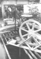
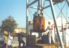
On October 14, 1916, during a tour of the surface and underground facilities by Friedrich Franz IV , the Grand Duke of Mecklenburg-Schwerin, photographs of the factory facilities were also taken.
Preparation and arrangement of the deposit areas
In order to be able to build and operate a safe and profitable mine in the Conow salt dome, which has only been investigated by four deep boreholes, a certain willingness to take risks was required, in particular, high mining expertise. After the shaft had been brought down, several investigation stretches and horizontal boreholes (some over 400 m long) were necessary for further investigation of the saline formation of the salt dome.
After the shaft had been built to a depth of 592 m in 1914, the first main levels were struck on July 4, 1913 at a depth of 380 m, on November 9, 1913 at a depth of 480 m and on January 21, 1914 at a depth of 580 m. Later - after reaching the final shaft depth of 720 m - the 706 m bottom was added. The individual soles were connected to one another by five blind shafts, from which several partial soles (also known as midsoles) were created.
Extraction, extraction and offset
The steep saline layers of the Conow salt dome, which sometimes change rapidly at short intervals, required a large number of main and partial levels.
- From the 380 m level (profile 3.00 × 2.30 m), exploratory crosscuts were set to the north and west , which were set in the north in the older rock salt of predominantly rare purity and in the west in sylvinite . On October 13, 1913, about 45 m from the main shaft, a first inflow of caustic (approx. 0.2 l / h) was noticed. Based on the experience gained during the operation of the neighboring potash works in Lübenheen , the dismantling of this sylvinite deposit was refrained from because of the further caustic inflows to be expected in the wall.
- The 480 m level (profile 3.00 × 2.30 m) was driven to the north and south. Only sylvin-rich hard salt was mined here in the southern field. So-called "sloping butt construction " (now known as a striking partial bottom chamber construction with pus-like displacement ) was used as the mining method , with the total construction height reaching 22 m with a mining width of around 6 m. The cross passages are, apart from a few places where narrow layers of carnallite , hard salt , sylvinite and anhydrite were passed, without exception, in younger as well as older rock salt . The striking stretch to the west at Blindschacht II is also covered with rock salt. The other striking investigation stretches in the southern field follow the hard salt deposits. The 480 m level served primarily as the main weather bed .
- The 580 m level was the main delivery level (profile 3.50 × 2.30 m) and had a filling point lined to the north and south . It opened up a rock salt field (older rock salt) in the north, in which four mines were created using the so-called "ridge construction process" (now more correctly referred to as open chamber construction in several slices with ridge- like displacement ) with a maximum length of 103 m, 22 m width and 16.5 m height were. The extracted salt was sold as table and industrial salt. In the south, the hard salt stores A and B as well as the so-called northern and C-carnallite stores were dismantled. The width of these excavations, also called the ridge construction method (today's name: delete the ridge joint construction with and without subsequent offset), extended over the entire thickness of the steep bearings and measured up to 45 m. The height of these excavations was up to 22.2 m, the excavation length up to 52 m. The latter was mostly limited by the necessary safety pillars that were required to stand opposite routes and dismantling. The SW on the III. The cross passage driven at 580 m level cut through an approximately 5 m thick hard salt deposit 28 m from the center of the shaft and then a carnallite deposit of the same thickness. In a later amendment of February 13, 1918, the carnallite store is given as 15 m, the hard salt store as 8 m and the stratum collapse at 80–90 °.

- The 706 m level, accessed from blind shaft I in profile 3.50 × 2.30 m, was only driven to the north as far as under the main shaft and later connected to it, especially for weather management. This stretch to the south, which is nevertheless known as the “main cross passage”, is also covered with rock salt. Here in the southern field the deep hard salt deposits A and B and the carnallite deposit C were dismantled. The construction height in hard salt store A reached a maximum of 22 m, in camps B and C it was limited to 12.2 m. The width of the mines encompassed the entire width of the deposit.
The partial soles (midsoles) listed below were created for the construction of the mining fields, for weather management and / or for the immediate mining facility itself.
- The 500-m sublevel only provides the Lying route is the "shock construction" in Südfeld the 480-m level. She was nowhere durchschlägig .
- The 530 m subsoil , developed from blind shafts II and III, opened up hard salt storage A through one mining and hard salt storage B through two excavations. The width of these excavations also covered the entire depth of the deposits; the excavation height was limited to 4.5 m. In the direction of strike, this sole stands in hard salt with a width of up to 5 m. It crosses the rock salt with a width between 3 and 5 m. It was necessary for orderly weather management.
- The 560 m sub-level was set from blind shaft V as an offset section for the carnallite structures 5, 6 and 7 of camp C of the 580 m level. Blind shaft V, which was only started in 1922, was referred to as the “backfill high break”. The 550 and 570 m levels going from it were called part level B and A. Part level B was only about 25 m long. Part level A served as a weather and backfill section of the carnallite camp C. It had a connection to the 580 m level in the south-eastern part of the field via blind shafts III and V, and in the south-western part of the field via the backfill.
- The 635 m partial level was the head section for the 645 m partial level. The latter opened up a carnallite store located west of the main crosscuts in a dam, which also has an east-west strike. This partial sole stood in the rock salt, which was interspersed with narrow carnallite cords. The mines 1 and 2 set up here extend in their width over the entire depth of the deposit, which is up to 22 m thick. The construction height was 12.2 m.
- The 686-m partial level , driven from blind shaft IV to the east 1 excavation (C.1.0.) Of the 706-m level, was intended to serve as an offset section for this elongated and high excavation.
- In the hanging wall of mining C.1.0. the 696 m partial floor was driven north into the Older Rock Salt. Here, a so-called has been Mountains mill created from which the workings C.1.0., C.2.0. and C.3.0. should be moved up to partial level. At the same time, an attempt was made from Blind Shaft IV in the opposite location to connect the 696 m partial floor to the western field.
Despite the variety of the ground plan forms of potash mining due to the geological conditions, the following simplified mining scheme can be summarized:
- Stroking cutting : The cutting width corresponds to the thickness of the deposit. The length of the mines is dependent on the thickness and is up to 50 m for deposits over 8 m thick, and up to 100 m in length for deposits below 8 m.
Piers around 10 m thick were left between the dismantling operations. If the excavation width exceeded 15 m, every third pillar was approximately 15 m thick. The height of the ridges reached 12.20 m in carnallitite and up to 24 m in hard salt. The mine workings - with the exception of the main shaft down to a depth of 593.80 m and the filling point of the 580 m level - were all without expansion. In the common (mining term for little stability) carnallite mining was introduced dry backfill . This consisted of rock salt or vertaubtem (inferior) hard salt from the Roadway drivages and out of the mountains mill, from the from the uphole salt mill ausgeklaubten rock salt, from slaked boiler house ash and from the material of the slag heap , which was created during shaft sinking Conow and Roadway drivages. The misalignment was brought about by falling ("tipping in" of materials). Individual workings have remained without sets, others are currently below the First full debris .
In the quarries, the crude salts were loaded into the trolleys by hand using shovels. The promotion of the loaded trolley made on laid mine train -Rails either manually or through open (per reel ) and closed cable production (so-called "endless cableway"; comparable to the ski lift system). The trolleys were "taken along" by the rotating steel cable by means of driving forks (a driving fork is a fixed fork-shaped device on the trolley into which the hauling rope is inserted).
According to the mining book entries and archived mining authority records, the work in the mine and surface operation proceeded without any particular disturbances compared to the other potash works in Germany at the time. Unfortunately, there were also 5 fatal accidents in the Conow potash plant (two in 1913; one each in 1914, 1922 and 1925) and one fatal accident in the Malliss lignite mine in 1925. A major operational disruption occurred in March 1922. On the weather side of the main shaft (see illustration on the right: Conow shaft disc), sintered salt fell two times , caused by the penetration of salt water through leaks in the cast iron tubbing column at a depth of around 140 m (in the plaster hat area) . The warm weather flowing out of the pit was conducted in the weather section of the Conow single shaft system. This warm air withdrew the water from the strongly salty seeping solutions and thus, over the course of time, extremely heavy salt precipitates were formed, which suddenly crashed due to their own weight and, in particular, smashed the wooden lining of the shaft fittings underneath. The manhole repairs lasted from March 17 to April 3, 1922. By injecting cement milk behind this segment, it was possible to achieve tightness again. However, the severity of these crashes must have been enormous, because even the press reported on this malfunction.
The fissures, cracks and ravines in various salt layers found in the mine area are more due to geotectonic than to subrosive effects. For example, a fissure on the 500 m level to the north, which was verified by a horizontal borehole (designated in the drilling profile as "Rachel" with a width of 1.1 m) that was driven north on the 706 m level. Another gap was discovered in September 1921 in mine 2 of the 645 m level. At the height of the ridge there was a cavity about 0.5 m in diameter and 5–6 m in length, which was filled with loose carnallitite. Also in the striking stretch to the west (northern border of the eastern carnallite camp of the 580 m level, in front of the bend of the carnallite camp to the south), a cavity about 3.5 m wide was also found in September 1921 at a route length of 75.2 m, 4 m in length and 10 to 12 m in height. This cavity had an approximately elliptical cross-section with a sharply delimited sliding surface at the western face; In it were about 130 wagons of carnallitite with an average of 11.7% K 2 O.
The appearance of caustic in an investigation section in the south-eastern field of the 580 m level in 1924 caused the mine administration to stop any blasting work in this area. Damming measures were prepared, but not completed after the lye inflows decreased ( for details on the lye situation, see: Lye inflows into the salt mines of Southwest Mecklenburg ).
In a note of Mecklenburg-Schwerin's mining authority of 26 July 1925, literally means: "The undersigned mining authority it is not on to explain that since entry of these circumstances - that seem to prove a well-founded in the mountain structure of the Mecklenburg Kalisalzlager special liquor hazard - on A long service life for the Conow potash mine was no longer to be hoped for, that rather the likelihood of a worsening of the inflows and thus, as experience has shown that shut-off measures are not very successful, the mine workings were drowned ”.
Factory operation
| month | Cainite | Carnallite | Rock salt | Picked up | Relocated | Total funding | every layer | Rest days |
|---|---|---|---|---|---|---|---|---|
| metric tons | metric tons | metric tons | metric tons | metric tons | metric tons | metric tons | number | |
| January | 1408.0 | 7276.6 | 914.6 | 61.6 | 186.1 | 9599.2 | 400.0 | 0 |
| February | 1155.3 | 6990.9 | 998.8 | 55.2 | 328.6 | 9145.0 | 415.67 | 0 |
| March | 694.3 | 7490.9 | 518.2 | 47.8 | 516.5 | 8703.4 | 395.6 | 4th |
| April | 235.9 | 5052.7 | 965.8 | 31.9 | 242.6 | 6254.4 | 481.1 | 10 |
| May | 368.55 | 5211.6 | 1660.6 | 40.0 | 118.7 | 7240.75 | 517.2 | 10 |
| June | 987.2 | 6998.1 | 1275.7 | 79.7 | 363.9 | 9261.0 | 419.6 | 4th |
| July | 250.4 | 7458.5 | 1936.6 | 53.8 | 321.1 | 9645.5 | 401.9 | 2 |
| August | 676.9 | 8255.2 | 1212.5 | 64.5 | 460.0 | 10144.6 | 390.2 | 0 |
| September | 197.25 | 4519.7 | 1365.0 | 30.6 | 128.2 | 6081.95 | 405.5 | 6th |
| October | 215.9 | 4595.2 | 2256.9 | 28.9 | 233.1 | 7068.0 | 353.4 | 8th |
| November | 83.1 | 3878.0 | 1952.8 | 23.5 | 206.5 | 5913.9 | 394.3 | 9 |
| December | 160.2 | 4661.6 | 5223.1 | 32.9 | 259.8 | 10044.9 | 558.05 | 3 |
In the Conow shaft area, the extracted salt was only ground and temporarily stored. The raw salt mill had two systems of 35 t each. The production took place in Friedrich Franz's factory [meaning the neighboring Friedrich Franz Lübenheen mine], with whom a corresponding contract was concluded. The factory was bought by the Conow union in 1916, when the Friedrich-Franz-Schacht was drowned. The storage shed for the ground crude salts had a storage space of 10,000 t. The material to be conveyed was processed in a crude salt mill in the Lübenheen factory with three grinding systems and a chlorinated potassium factory. Of the 3 grinding systems, one was used to process factory salt, the second to produce the Kainit brand and the third to grind rock salt. Each system had a capacity of 40-45 tons per day. The factory produced potassium chloride and high-percentage fertilizer salt, as well as large quantities of sulfuric acid salts. It processed approx. 500 t per day. Rock salt, chlorine magnesium ( magnesium chloride ), block kieserite , bromine and probably also Epsom salt were produced as by-products. The final liquor from the factory was conveyed to the Elbe through a 17 km long cast iron pipeline, whereby the wastewater concession was unlimited.
In 1923, due to a lack of sales, there were repeated holiday shifts: in March 4; on April 10; on May 10; on June 4; on July 2; on September 6; on October 8; on November 9; in December 3. The table shaft extraction in 1923 is intended to bring the reader closer to the difficult economic situation of the potash plant.
Shutdown
At the beginning of the 20th century, drilling activities in Germany experienced a real boom after the search for salt and hard coal deposits . The technical and technological improvements of the drilling rigs - at that time it was z. For example, it is already possible to extract complete drill cores in saline rock strata using diamond drill bits - and the financial willingness of the banking industry to grant appropriate loans for the search and exploration of new deposits, ultimately led to the acquisition of new deposit fields via requests for advice . In order to prevent the proliferation of new potash works (as well as hard coal mines ) and thus overproduction, the Prussian state parliament passed, at the request of MP Karl von Gamp-Massaunen, among other things, the “ Law on the Amendment of the General Mining Act of June 24, 1865/1892 , dated July 5, 1905 (GB, p. 265) ”, so referred to as Lex Gamp . It initially led to a temporary ban on speculation of potash salts and hard coal for two years. This meant that only the state could acquire mining property. The latter was able to transfer it to third parties in the form of a time-limited real extraction right.
The Lex Gamp was the beginning of further state interventions to avoid the formation of monopoly up to the regulation of prices and the overproduction caused by the excessive increase of potash mines. The so-called decommissioning ordinance of October 22, 1921 (" Ordinance on the amendment of the regulations for the implementation of the law on regulating the potash industry of July 18, 1919", Reichs-Gesetzblatt p. 663 ) served to regulate the potash market.
In § 83a of this ordinance it says (here in the 1st paragraph of § 83a, applicable to the Conow plant): "A change in the circumstances relevant for the assessment remains until December 31, 1953 on the continuation and the amount of the participation figure of those plants without influence, which are voluntarily shut down up to this point in time. An irrevocable declaration to this effect must be submitted to the potash inspection office by April 1, 1923 (extended to December 31, 1926). Taking into account the economic situation, in particular the salt stocks, this determines the point in time by which the shutdown must be carried out; an extension of this period beyond April 1, 1924 is not permitted. A shutdown within the meaning of this paragraph requires that any extraction of usable minerals from the shutdown shaft ceases. Exceptions can only be granted by the Reich Minister of Economics after hearing the Reichskalirat and the potash testing office ”.
Due to the war-related labor shortage and the economic problems after the end of the First World War , the production capacity in the Conow potash plant remained at a low level. In Germany, around 40 percent of all potash plants were shut down or deferred for a limited period in 1925/26 . Of the 147 potash plants in Germany in 1921, 79 plants were finally shut down. The Conower plant was also affected by this development. As a single company, unlike the larger potash groups with several pits , they could not face the increasing competition .
The closure of the union was decided by the majority of the unions at the union assembly in Berlin on December 29, 1925. The union sold the portion of potash products stipulated for Conow by the potash certificate of 1919 to the Westeregeln Group for 3 million marks. The entire system was shut down in 1926 and the pit void volume (approx. 320,800 m 3 ) was flooded by introducing mineralized solutions from the overburden .
In 1926, the geologist Ernst Fulda reported on the salt deposit of the Conow potash plant, which was registered for closure. In 1936 he examined a. a. the safety of the surface above the mine workings of the now closed potash and rock salt mine Conow.
Flooding
| stretch | approx. 92,200 m 3 |
| Workings (non-set) | approx. 211,000 m 3 |
| Blind shafts | 2,400 m 3 |
| Main shaft | 15,200 m 3 |
| total | approx. 320,800 m 3 |
The shutdown was limited to December 31, 1953. Flooding the mine was supposed to ensure safe storage until it was put back into operation. In order not to flood with fresh water, the salt water in countless crevices and crevices of the salt cap (depth range 51–160 m) should be used for flooding. The table on the right lists the cavities that were still open before flooding.
Before the mine workings were flooded, all furnishings that could still be used were removed. To introduce the salt water into the mine building, the segments were drilled at a depth of 120 m and three high-pressure taps were installed. The recordings indicate that a pressure of 13.2 at was measured at the tapping points . The density of the salt water was 1.202 g / cm 3 .
Flooding began on August 7, 1926. The salt water was by means of a on a track bar strand fastened low promotion rectangular wooden luttentour (100 x 200 mm) for the filling location of the 480 m level and from there by means of a bend directed in the eastern route. The further flooding path ran over the main cross passage to the south, over the blind shaft II to the 580 m level, on through the eastern constructions to the weather borehole , then to the 645 m level and over the blind shaft I to the 706 m level. Weak dams were built to maintain this path. So z. B. on the 580 m level in the diagonal cable car route leading from the main cross passage to Blindschacht II, in order to prevent the water from directly penetrating the shaft.
For the flooding process, operator v. Boremski began in his documentation with the introduction of 192 m 3 gypsum hat water on August 7, 1926. According to this documentation, a cumulative total of 281,000 m 3 were discharged by April 30, 1927 (on some days up to 5,000 m 3 ). According to calculations, such an amount exceeded the productivity of the open flooding taps, so that in addition to the gypsum hat waters, considerable amounts of fresh water must have been discharged from above ground. During the flooding, the water levels in five nearby wells were observed. Changes that could be due to the flooding were not found.
After the water had risen to the taps in the shaft tube, according to the records of the mine administration, these were closed. The shaft tube area above was filled with fresh water. As can be seen from the table above, the total void volume of all mine workings was approximately 320,800 m 3 . However, since air-filled cavities remain even if a mine is flooded, the exact amount of water discharged into the Conow salt mine cannot be precisely quantified.
On behalf of the Oberbergamt Halle / Saale, Bergrat Ludwig Tübben - professor of mining science at the Bergakademie Berlin and later at the Royal Technical University of Berlin - drove into the Conow mine, which was flooded, on August 28, 1926. He reported that the solution-related destruction on the line joints in the hard salt was insignificant and only noticeable to a small extent in the rock salt and carnallite. The well-known old caustic drip points in the pit also remained unchanged.
The mine book of the mine was closed on March 8, 1928.
Dismantling of the plant
After the headframe and the main and secondary hoisting machine buildings had been dismantled in 1927, access to the shaft tube was secured by a circular wall with an embedded rail grid. There is no archival documentation of anything about the further demolition of buildings, for example the large storage facility or the grinding plant. Bergrat Loewe acted as the liquidator of the Conow union . With a notary contract of March 20, 1927, he sold the last operator of Boremski, among other things, the "property lot 1" (that was the entire shaft area) with the exception of the shaft opening (purchase price 20,000 RM ). With a further notarized purchase agreement, also dated March 20, 1927, von Boremski also became the owner of the Doppelhäuslerei No. 34 in Conow (the former factory casino; purchase price 4000 RM ). This property changed hands on August 27, 1930 for 10000 GM (the new owner became the Conower businessman Albert Peters ).
Removal of a solder obstacle
With the decree of the GDR in custody dated October 19, 1971 (GDR 1971 II p. 621), the council of the district of Schwerin was appointed for the three potash works Jessenitz, Lübenheen and Conow, so-called "Grubenbaue old mining without legal successors", responsible.
After the pits of the Conow mine were flooded in 1926, in addition to archival research, extensive research work was carried out on and in the shaft tube by the district office for geology at the Schwerin District Council (later - through incorporation into the Schwerin District Council - by the Geology Department of Council of the District of Schwerin). In addition to other work, it was necessary to extract the water and salt solutions from the Conow shaft, to analyze them and to check their information content with regard to negative subrosive processes that had occurred or were still to be expected . This plumbing and sampling work was impaired by an insurmountable solder obstacle at a depth of around 480 m. This so-called mirror coating (mining term for an obstacle that hinders the movement; here a vertical obstacle) - at the time deliberately built in to control the flood water - ultimately had to be removed by a targeted blasting (see the following photo series).
The blast was carried out by a measuring train from VEB Geophysik Leipzig, borehole measurement department . After the blast, unhindered access was possible to take further solution samples down to the shaft depth of 675 m.
For the first time in 1981 an attempt was made to evaluate the subrosive processes that have already expired and those that are still to be expected in the salt mining pits, using the chemical information content of water and solution samples taken from drowned or flooded shafts of these mines. The first investigations in this regard were carried out at the Conow shaft.
After submitting these analysis results and their physico-chemical interpretation (i.e. mineralization of the solutions in the various depths and their relationship to the surrounding salt rock), no further saline dissolution processes are to be expected in the Conow shaft area. These statements were confirmed by the echometric cavity measurements carried out in 2004.
Situation on the shaft head protection

Winch vehicle from VEB Geophysik Leipzig
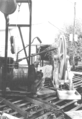
View from the shaft to the winch vehicle

Loading the dip tank with explosives

Arming the explosive charge

The "remains" of the explosive device


Further security measures
In the years 1984 to 1986 the previous walling of the shaft tube was demolished and the shaft opening was secured by means of a reinforced concrete cover plate (diameter 6.51 m). In this cover there was an access hatch and a control hatch (both with a diameter of 0.6 m), secured by means of a cast iron cover. Three warning systems were installed on a control platform 3.26 m below the floor, which were supposed to register movements or even breaks within the shaft tube. Their measuring anchors were in the depths of 11.5 m, 40.0 m and 60.0 m.
The weather channel was filled with lean concrete and the upper shaft lining was renovated. After completing this safety work, the Stralsund Mining Authority had a new safety radius of 24 m around the shaft tube, because there was a risk of a sudden failure of the near-surface shaft lining and the falling of the reinforced concrete slab, combined with dangers for uninvolved third parties and the development near the shaft.
The successor company of the former " VEB Nordfrucht Conow " (since 1992 belonging to the Nestlé Group under the name " WCO Kinderkost GmbH Conow ") endeavored to carry out permanent custody of the Conow shaft with the aim of abolishing the shaft security area. In 1994 the Stralsund Mining Authority commissioned ERCOSPLAN Ingenieurgesellschaft Geotechnik und Bergbau mbH Erfurt to develop such a custody project .
Safekeeping of the shaft tube
The aim of the safekeeping was to prevent possible breakage processes in the area close to the surface over a period of several decades in order to enable the resident company to use the areas permanently. "After considering possible storage options , it was decided to only secure the shaft head area and to keep the remaining shaft tube in compliance with the solution."
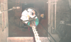
For this purpose, a load-bearing shaft seal was installed from September 1996 to November 1996 in the area of the Quaternary loose rock masses from 0 to 51 m depth. To do this, divers had to remove the sealed areas up to a depth of 54.5 m and a formwork platform had to be installed under water (see video clip). After making a pre-plug from underwater concrete , the sump work and the robbery of the manhole installations began . The shaft seal is a reinforced concrete structure consisting of a shaft that fills the shaft up to a depth of 51 m and is shifted in the protruding shaft head area (Ø 10 m, approx. 1.5 m high). Concrete of strength class B 25 was used to fill the shaft up to the bottom of the lawn . After the work was completed, the risk of sudden failure of the uppermost section of the shaft lining was permanently eliminated. In the following years the condition was regularly monitored through subsidence measurements and control plumbing.

Entry into the weather channel in 1975

Shaft view in 1975 (with installed warning systems)
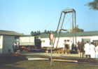
Overall view of the conveyor system on the occasion of the maintenance work on the Conow shaft
View down into the shaft: Entry of the feed bucket into the Conow shaft
Exit of the conveyor bucket occupied with people

View of the pit area (left 1975; right 2010)


Final cavity exploration
In 2004, the Stralsund Mining Authority initiated another investigation into the stability of the Conow shaft. The reason was that during investigations by means of an investigation and monitoring program designed for the specific conditions of the old potash wells (see also " Echometric cavity measurements ") in a large number of drowned shafts at the level of the saline rocks (mostly in the potash seam ) cavity structures ( e.g. around 18,000 m 3 am Leopoldshall III shaft in Staßfurt) and a collapse of the lower shaft sections were found.
Complex dissolution processes as a result of the uncontrolled drowning of the mines and shafts with unsaturated, aqueous solutions (mostly groundwater ) have been identified as the cause of the cavity formation .
Since similar sequences of events during the drinking were documented for the old potash shafts located in Mecklenburg, similar processes and the associated risks for the surface of the surface had to be assumed, especially for the Conow shaft secured with a near-surface concrete plug . In order to carry out the relevant investigations, it was necessary to completely pierce the concrete plug with a borehole and to install protective piping up to the final depth of the shaft at a depth of more than 700 m to protect the measuring equipment . After this was done, the planned measurements could be carried out. This made it possible to prove beyond doubt that more than 80 years after leaving the shaft, no changes in the shaft contour had occurred and the solutions in the shaft were in equilibrium with the surrounding salt rock. The geotechnical assumptions made during the partial custody of a largely undamaged shaft tube could thus be confirmed.
A final mining damage assessment comes to the conclusion that, according to human judgment, there are no dangers for the surface near the shaft used by an industrial company.
literature
- J. Bölsche, B. Hörig, G. Schraps u. a .: Conow-Lübenheen results report . Leipzig 1981 (Unpublished report by VEB Geophysik Leipzig; specialist archive of the State Office for the Environment, Nature Conservation and Geology Mecklenburg-Western Pomerania (LUNG MV) , inventory signature no. GYSM0603).
- Günter Pinzke: The salt mines of Mecklenburg . 1st edition. Books on Demand, Norderstedt 2014, ISBN 978-3-7357-7441-5 .
- Günter Pinzke: A contribution to the assessment of mining damage of disused potash and rock salt mines . Freiberg 1981 (dissertation, Bergakademie Freiberg , Geotechnical and Mining Section).
- Günter Pinzke: Assessment of the stability of the mine workings of the potash and rock salt mine Conow and the expected effects during the injection of liquid pollutants by means of drilling into the mine building . Freiberg 1976 (Unpublished diploma thesis, Bergakademie Freiberg, Geotechnical and Mining Section; Special Archives of the State Office for the Environment, Nature Conservation and Geology Mecklenburg-Western Pomerania (LUNG MV), inventory signature no. GM-003.525).
- Günter Pinzke: The salt production in southwest Mecklenburg - geology and development of the deposits; an outline of mining history. Part 2: Search, exploration and development of new salt deposits: the potash and rock salt mines Jessenitz, Lübheen and Conow. In: Association of Friends of Art and Culture in Mining e. V. (Ed.): THE cut . 64th volume, No. 2 -3, pp 76-92, 2012th
- Günter Pinzke: On the history of the mining and saltworks in Mecklenburg and their initiators . In: Scientific journal of the Wilhelm Pieck University Rostock . G series. tape 35 . Ostseedruck Rostock, 1986, ISSN 0323-4630 , p. 78-80 .
- Günter Pinzke: personalities of the mining and salt works in Mecklenburg . In: Schweriner Blätter . Contributions to the local history of the Schwerin district. tape 6 , 1986, ISSN 0232-7902 , pp. 56-59 .
- Günter Pinzke: For the calculation of saline dissolution phenomena in carnallitite . In: New mining technology . 17th year, 1987, p. 25-27 .
- Günter Pinzke: Mining damage analysis of the potash and rock salt mine Conow . 1975 (Unpublished report of the district office for geology at the advice of the district of Schwerin; specialist archive of the state office for the environment, nature conservation and geology Mecklenburg-Western Pomerania (LUNG MV, archive no. KA 0040.)).
- Günter Pinzke: Site assessment for the construction of structural facilities on the site of the disused potash mine Conow . 1975 (Unpublished report of the district office for geology at the advice of the district of Schwerin, archive of the MV Stralsund mining authority.).
- Günter Pinzke, Thomas Triller, Andreas Jockel: Potash and rock salt mining in SW Mecklenburg . In: Martin Froben (Hrsg.): 20 years Bergamt Stralsund . 1990-2010. Ministry of Economy, Labor and Tourism Mecklenburg-Western Pomerania, Neubrandenburg 2010, p. 46-55 ( mvnet.de ).
- Final report on the safekeeping of the Conow mine . Nordhausen 1986 (unpublished report of the VEB Schachtbau Nordhausen; specialist archive of the State Office for the Environment, Nature Conservation and Geology Mecklenburg-Western Pomerania (LUNG MV), inventory signature no. KA 0037).
Web links
- More photos of the Conow mine, including those of the daytime systems and underground views during the flooding of the mine
- Videos about a control trip and the shaft custody of the Conow shaft
- Lars Baumgarten: Germany's potash and rock salt pits. 7.3 Conow. Retrieved December 9, 2013 (photos, coordinates).
- Günter Pinzke: Old mining in Mecklenburg-Western Pomerania. Retrieved May 10, 2016 (documentation).
Explanation of the technical terms
- ↑ The qualitative and quantitative calculation of the various potash salts is based on their fictitious K 2 O content (conversion factor: 100% KCl corresponds to 63.17% K 2 O).
- ↑ Even before 1900 there was a provision in the Clausthal District Mining Authority, according to which all mining facilities should have two separate, mobile exits to the surface, i.e. a target regulation. This was not the case in Mecklenburg, but the Mining Authority was free to order a special provision for salt mines as to whether and by what time they were to be provided with a second exit. However, there was no relevant official order for the three Mecklenburg potash mines.
- ↑ The direction that runs horizontally across the longitudinal axis of the deposit is referred to as cross-cutting . (Source: Förderverein Rammelsberger Bergbaumuseum Goslar e.V. (Ed.): Ore mining in Rammelsberg .)
- ↑ Mountain mills in potash mining are quarries created in rock salt which were used to extract backfill material for the common carnallite mining chambers. (See also 5dic.de - dictionary of technology. Accessed on 22 March 2013 . )
Individual evidence
- ↑ a b c d e f Gerhard Katzung, Klaus Granitzki: Salts. In: Geology of Mecklenburg-Western Pomerania. E. Schweitzerbart'sche Verlagbuchhandlung (Nägele and Obermiller), Stuttgart 2004, ISBN 3-510-65210-X , p. 423 f.
- ↑ a b Günter Pinzke: The salt production in southwest Mecklenburg - geology and development of the deposits; a mining historical outline; Part 2. In: The cut . Volume 64, Issue No. 2-3, 2012, p. 88; For the current use of the shaft area, see also WCO Kinderkost GmbH Conow. Retrieved March 22, 2013 .
- ↑ a b c Werner von Bülow: Geological overview. In: Werner von Bülow (Ed.): Geological development of southwest Mecklenburg since the Upper Oligocene . Series of publications f. Geowissensch., Heft 11, Berlin 2000, p. 3 f.
- ↑ a b c Werner von Bülow: Storage conditions since the Chatt, derived from outcrops. In: Werner von Bülow (Ed.): Geology of Southwest Mecklenburg since the Upper Oligocene . Series of publications f. Geowissensch., Heft 11, Berlin 2000, p. 395 f.
- ^ Werner von Bülow: Historical use and research history of SW Mecklenburgs. In: Werner von Bülow (Ed.): Geology of Southwest Mecklenburg since the Upper Oligocene . Series of publications f. Geowissensch., Heft 11, Berlin 2000, p. 7 ff.
- ↑ Manfred Petzka: Halokinesis and tectonics in the paleogene and deeper neogene. In: Werner von Bülow (Ed.): Geology of Southwest Mecklenburg since the Upper Oligocene . Series of publications f. Geowissensch., Heft 11, Berlin 2000, p. 378.
- ↑ Günter Pinzke: Salt production in southwest Mecklenburg - geology and development of deposits; a mining historical outline; Part 2. In: The cut. Volume 64, Issue No. 2-3, 2012, pp. 84 ff .; VEB Geophysik Leipzig (Ed.): Conow-Lübenheen results report . Leipzig 1969.
- ↑ a b c d e f Günter Pinzke: The salt production in southwest Mecklenburg - geology and development of the deposits; an outline of mining history . In: The cut . 64th year, no. 1, 2-3 , 2012, pp. 18-24 u. 76-92 (here p. 85).
- ^ Werner von Bülow: Historical use and research history of SW Mecklenburgs. In: Werner von Bülow (Ed.): Geology of Southwest Mecklenburg since the Upper Oligocene . Series of publications f. Geowissensch., Heft 11, Berlin 2000, p. 8.
- ↑ a b c d Günter Pinzke: The salt production in southwest Mecklenburg - geology and development of the deposits; an outline of mining history . In: The cut . 64th year, no. 1, 2-3 , 2012, pp. 18-24 u. 76-92 (here p. 86).
- ↑ a b c d e f g Gerhard Katzung, Klaus Granitzki: Salts. In: Geology of Mecklenburg-Western Pomerania. E. Schweitzerbart'sche Verlagbuchhandlung (Nägele and Obermiller), Stuttgart 2004, ISBN 3-510-65210-X , p. 424.
- ↑ Günter Pinzke: Salt production in southwest Mecklenburg - geology and development of deposits; a mining historical outline; Part 2. In: The cut. Volume 64, Issue No. 2-3, 2012, pp. 84 ff .; Günter Pinzke: Mining damage analysis of the potash and rock salt mine Conow . Ed .: District Office for Geology at the Council of the District of Schwerin, Department of Geology. Stralsund 1975 (Bergamt Stralsund archive; unpublished report).
- ↑ Hanspeter Jordan, Hans-Jörg Weber (ed.): Hydrogeology - Basics and Methods. Regional hydrogeology: Mecklenburg-Western Pomerania, Brandenburg and Berlin, Saxony-Anhalt, Saxony, Thuringia . Ferdinand Enke, Stuttgart 1995, ISBN 3-432-26882-3 , p. 285 f.
- ↑ Hanspeter Jordan, Hans-Jörg Weber (ed.): Hydrogeology - Basics and Methods. Regional hydrogeology: Mecklenburg-Western Pomerania, Brandenburg and Berlin, Saxony-Anhalt, Saxony, Thuringia . Ferdinand Enke, Stuttgart 1995, ISBN 3-432-26882-3 , p. 308.
- ↑ a b Markus Wehring: Hydrogeological report DE Grebs . VEB Hydrogeology Nordhausen, 1974; 2 volumes, 11 tables, 22 appendices; available in the archive of the State Office for the Environment, Nature Conservation and Geology Mecklenburg-Western Pomerania (LUNG MV, inventory signature HYEB0353)
- ^ Franz Eugen Geinitz: Contribution to the geology of Mecklenburg . Carl Hinstorffs Hofbuchdruckerei, Rostock 1922, p. 167 .
- ↑ Werner von Bülow: Storage conditions since the Chatt, derived from outcrops. In: Werner von Bülow (Ed.): Geology of Southwest Mecklenburg since the Upper Oligocene . Series of publications f. Geowissensch., Heft 11, Berlin 2000, p. 396.
- ↑ Werner von Bülow: Geological overview. In: Werner von Bülow (Ed.): Geology of Southwest Mecklenburg since the Upper Oligocene . Series of publications f. Geowissensch., Heft 11, Berlin 2000, p. 4.
- ↑ Günter Pinzke: Salt production in southwest Mecklenburg - geology and development of deposits; a mining historical outline; Part 1: The Conow Saline. In: The cut. Volume 64, Issue No. 1, 2012, p. 22 f.
- ↑ a b c d e f g Günter Pinzke: The salt production in southwest Mecklenburg - geology and development of the deposits; an outline of mining history . In: The cut . 64th year, no. 1, 2-3 , 2012, pp. 18-24 u. 76-92 (here p. 87).
- ↑ a b Kuxen department of the Mitteldeutsche Privat-Bank, Die Aktiengesellschaft (concerning " Union Conow in LÜBTHEEN iM " (Ed.): Kali-Handbuch for the year 1920. Magdeburg May 1920, p. 214/215 .
- ↑ Bergamt Stralsund: Historical outline of the Malliss mine . ( Memento of the original from February 24, 2014 in the Internet Archive ) Info: The archive link was automatically inserted and has not yet been checked. Please check the original and archive link according to the instructions and then remove this notice. Ministry of Energy, Infrastructure and Regional Development Mecklenburg-Western Pomerania, accessed on April 18, 2013.
- ↑ History Group SBN shaft sinking Nordhausen technology in transition, company history Volume 2 Part 1 . Print Media Center Gotha, 2006, ISBN 3-9811208-0-9 , p. 54 .
- ↑ a b Günter Pinzke: The salt production in southwest Mecklenburg - geology and development of the deposits; a mining historical outline; Part 2. In: The cut. Volume 64, Issue No. 2-3, 2012, p. 86 f.
- ↑ State Main Archive Schwerin, inventory 5.12-3 / 18 (Mecklenburg-Schwerinsches Bergamt), No. 38 (files concerning the cable car ride on the Conow mine).
- ↑ a b c d e f Günter Pinzke: Selected archive material on the operation of the Conow potash and rock salt mine. (PDF; 164 kB) Accessed March 28, 2013 . PDF on Günter Pinzke's homepage
- ↑ State Main Archive Schwerin, inventory 5.12-3 / 18 (Mecklenburg-Schwerinsches Bergamt), No. 38 (files concerning the cable car ride on the Conow mine).
- ↑ Günter Pinzke: The history of the mountain and Saline nature in Mecklenburg and its initiators. In: Scientific journal of the Wilhelm Pieck University Rostock. G-series 35, issue 2, Rostock 1986, ISSN 0323-4630 , pp. 78-80.
- ↑ Visit by Grand Duke Friedrich Franz of Mecklenburg-Schwerin on October 14, 1916 (PDF; 4.5 MB).
- ↑ Günter Pinzke: Salt production in southwest Mecklenburg - geology and development of deposits; a mining historical outline; Part 2. In: The cut. Volume 64, Issue No. 2-3, 2012, p. 87; on the mine workings cf. also “Grubenbild trade union Conow”, State Main Archive Magdeburg, inventory signature Reg. F: Riss Archive No. 3488–3499, 3501–3506, 4475. created by Markscheider W. Weber, Magdeburg.
- ↑ a b State Main Archives Schwerin, holdings 5.12-3 / 18 (Mecklenburg-Schwerinsches Bergamt 1900–1943) and 10.21-13 (Union Conow zu Lübenheen 1911–1927) Günter Pinzke: Union Conow. (PDF; 1.8 MB) Retrieved March 28, 2013 . P. 5/6, PDF on Günter Pinzke's homepage
- ↑ State Main Archives Schwerin, inventory 5.12-3 / 18, No. 37 (files relating to the operation of the Conow mine, 1917–1929), operational plan of the Conow salt mine for 1925, p. 55.
- ↑ State Main Archive Schwerin, inventory signature 5.12-3 / 18, No. 33, " Mecklenburg-Schwerinsches Bergamt ", " Files relating to accidents at the Conow and Malliss mines ", pages unnumbered.
- ↑ State Main Archives Schwerin, inventory 5.12-3 / 18, No. 37 (files relating to the operation of the Conow mine, 1917–1929), operational plan of the Conow salt mine for 1925, p. 55.
- ↑ Million damage in the Conow potash mine. In: People's Watch. No. 67, March 21, 1922.
- ↑ Kaliarchiv Staßfurt, inventory no. A 1, C 0, 1 b, 1–16, diaries (sinking reports, operating reports, funding statistics), 1911–1926.
- ↑ State Main Archives Schwerin, inventory signature 10.21-13, No. 15 Union Conow zu Lübenheen, 1911–1927 , pages unnumbered.
- ^ Horst Richter: Geological passport of the southwest Mecklenburg potash salt deposits . Ed .: Geological State Institute of the GDR. Ministry of Economics, State Geological Institute, Mecklenburg branch, 59 pages, 9 attachments, Rostock 1950 (LUNG MV archive, inventory signature KA0001).
- ↑ State Main Archives Schwerin, holdings signature 10.21-13, No. 15, Union Conow zu Lübenheen 1927-28 , pages unnumbered.
- ↑ On the development of mining law in the western part of the Prussian state. Retrieved February 1, 2013 .
- ^ Adolf Arndt: General mining law for the Prussian states . 5. verb. u. probably edition. Leipzig 1907 ( Max Planck Institute for European Legal History) [accessed on February 1, 2013]).
- ^ Harm Peter Westermann , Dieter Eickmann, Karl-Heinz Gursky : Property Law, A Textbook. 8th edition. CF Müller, 2011, ISBN 978-3-8114-7810-7 , p. 76 ( online in the Google book search)
- ↑ Gerhard Leibholz, Peter Häberle (Ed.): Yearbook of the public law of the present. Volume 14, Mohr Siebeck, Tübingen 1965, ISBN 3-16-615942-8 , p. 207 ( online in the Google book search)
- ↑ a b Günter Pinzke, Thomas Triller, Andreas Jockel: The potash and rock salt mining in southwest Mecklenburg . In: Bergamt Stralsund (ed.): 20 years Bergamt Stralsund. 1990-2010 . Ministry of Economy, Labor and Tourism Mecklenburg-Western Pomerania, Neubrandenburg 2010, p. 49 . Ernst Fulda: Report on the safety of the surface at the potash works Friedrich Franz, Jessenitz and Conow in Mecklenburg . Ed .: Prussian Geological State Institute. Berlin 1936, p. 5 .
- ↑ Ernst Fulda: Report on the salt deposit of the Conow potash plant near Conow (Mecklbg.), Which has been registered for closure . Ed .: Prussian Geological State Institute. Berlin 1926, p. 1-4 .
- ↑ Günter Pinzke: Salt production in southwest Mecklenburg - geology and development of deposits; a mining historical outline; Part 2. In: The cut. Volume 64, Issue No. 2-3, 2012, pp. 87 f.
- ↑ State Main Archives Schwerin, inventory 5.12-3 / 18 (Mecklenburg-Schwerinsches Bergamt 1900–1943), No. 37 (Operation of the Conow Mine 1917–1929).
- ↑ a b c d e f Günter Pinzke: The salt production in southwest Mecklenburg - geology and development of the deposits; an outline of mining history . In: The cut . 64th year, no. 1, 2-3 , 2012, pp. 18-24 u. 76-92 (here p. 88).
- ↑ Royal Technical University of Berlin. Retrieved on April 9, 2013 (on Bergrat Ludwig Tübben (1869–1946) see entry on June 24, 1916).
- ↑ State Main Archive Schwerin, inventory 5.12-3 / 18 (Mecklenburg-Schwerinsches Bergamt, No. 60, files concerning the operation of the lignite mining in Malliss).
- ↑ State Main Archives Schwerin, holdings 10.21-13 (Conow union in Lübenheen 1911–1927), No. 25, (files relating to the dismantling of the Conow potash mine 1927). Compare
- ↑ Order on the safekeeping of underground mining facilities (safekeeping order). (PDF; 48 kB) Accessed January 14, 2013 .
- ↑ Günter Pinzke: Expert opinion on the assessment of the mining and public safety of selected potash pits without legal successors on the territory of the Halle district . Expert opinion, Council of the District of Schwerin, Geology Department, August 8, 1979, 4 annexes; Archive of the State Office for Geology and Mining Saxony-Anhalt.
- ↑ History of borehole measurement at the Storkow site. (No longer available online.) Archived from the original on May 1, 2015 ; Retrieved January 13, 2013 . Info: The archive link was inserted automatically and has not yet been checked. Please check the original and archive link according to the instructions and then remove this notice.
- ↑ Günter Pinzke: A contribution to the assessment of mining damage of disused potash and rock salt mines . Dissertation, TU Bergakademie Freiberg, 1981. Text volume pp. 1–110 (here Conow p. 51–59); Appendix volume pp. 111-215 (here Conow p. 195).
- ↑ Hans-Heinz Emons, Heidelore Voigt: Chemical and environmentally relevant aspects in the field of the mineral salt industry . Publishing house of the Saxon Academy of Sciences in Leipzig, 2003, ISBN 3-7776-1237-5 , p. 24 ff .
- ^ A b c d Günter Pinzke, Thomas Triller, Andreas Jockel: The potash and rock salt mining in SW Mecklenburg . In: Bergamt Stralsund (ed.): 20 years Bergamt Stralsund. 1990-2010 . Ministry of Economy, Labor and Tourism Mecklenburg-Western Pomerania, Neubrandenburg 2010, p. 51 f .
- ↑ a b c Günter Pinzke, Thomas Triller, Andreas Jockel: The potash and rock salt mining in southwest Mecklenburg . In: Bergamt Stralsund (ed.): 20 years Bergamt Stralsund. 1990-2010 . Ministry of Economy, Labor and Tourism Mecklenburg-Western Pomerania, Neubrandenburg 2010, p. 50 .
- ↑ Johann Christoph Adelung: Grammatical-critical dictionary of the high German dialect. Retrieved January 28, 2013 .
- ↑ Guideline November 5, 1979. Guidelines of the LOBA NRW for the filling and covering of day shafts dated November 5, 1979, in the version dated March 14, 1983. (No longer available online.) Supreme mining authority of the State of North Rhine-Westphalia (Department 8 of the Arnsberg district government), (Former State Mining Authority "LOBA" NRW), archived from the original on February 25, 2014 ; accessed on January 28, 2013 . Info: The archive link was inserted automatically and has not yet been checked. Please check the original and archive link according to the instructions and then remove this notice.
- ↑ Hartmut von Tryller, Giesen: INFOBLATT Echometric cavity measurements, back and under insulation through covered, shaded areas in caverns. (PDF; 264 kB) (No longer available online.) December 1998, archived from the original on May 11, 2008 ; accessed on January 28, 2013 . Info: The archive link was inserted automatically and has not yet been checked. Please check the original and archive link according to the instructions and then remove this notice.
- ↑ J. Bodenstein, K. Salzer, P. Sitz, H. Rauche, D. Vetter: Comparative assessment of storage alternatives for old potash shafts. In: W. Busch, K. Maas, G. Meier, A. Sroka, K.-H. Löbel, H. Klapperich, D. Tondera (Eds.): "Lecture volume for the 5th Altbergbau-Kolloquium", Montanuniversität Leoben, 3rd – 5th November 2005. Verlag Glückauf, Essen 2005, pp. 330–344.
- ^ Andreas Jockel: Development of solutions in drained old potash shafts. In: Regional and Applied Geology in the Border Region of the South German and Central German Plaice. (= Proceedings for the 10th annual conference of the Society for Geosciences, September 19–22, 2001 in Schmalkalden ). Berlin 2001, pp. 135-137.
- ↑ Andreas Jockel, Gerhard Jost, Jörg Martin, Heidrun Rauche, Thomas Triller: Exploration of backfilled old potash shafts by means of shaft bores. (PDF; 487 kB) 2007, p. 99 , accessed on January 13, 2013 .