
Electron tube


An electron tube is an active electrical component with electrodes that are located in an evacuated or gas-filled flask made of glass, steel or ceramic. The connections of the electrodes are led out of the tube piston. In its simplest form as a diode , an electron tube contains a heated cathode ( hot cathode ) and an anode . Electron tubes are used to generate , rectify , amplify or modulate electrical signals .
Negatively charged elementary particles emerge from the hot cathode as free electrons and are moved to the anode by the effect of an electric field . This electron flow can be influenced by a control grid between the cathode and anode, because the electron flow is more or less inhibited by different grid voltages or electrical fields. The use of the electron tube as an amplifier or oscillator is based on this .
Until the introduction of the transistor, electron tubes were the only fast active (controllable) components in electronics . Until then, only transducers and relays were available as active two-port devices, whereby the latter only knew two states (on / off) and their switching speed was limited by the moving mass. Electrons have a much lower mass, so they can be used to process much higher frequencies.
Depending on the type of tube, it may contain a low-pressure gas that provides additional ion conduction and compensates for the effect of the space charge .
Even today, tubes are still in use in many areas. Powerful transmission systems are operated with electron tubes, magnetrons are used in radar systems and microwave ovens . Older televisions and computer monitors use cathode ray tubes . Tube amplifiers are also used as audio amplifiers in the high-end sector . Many electric guitarists and bassists also appreciate the characteristic sound of a tube amplifier. Fluorescent displays are used for the optical signaling of the device status of devices such as CD players, video recorders and so on, but are increasingly being replaced by liquid crystal displays and organic light-emitting diodes .
Several types of tubes with corresponding demand are still produced today, mainly in Russia and China. Some are still available from old (military) spare parts stocks ( New Old Stock ).
history


The physical chemist Frederick Guthrie discovered glow emission in 1873 , but without any practical effects. In 1880 the effect was observed again by Thomas Alva Edison in experiments with incandescent lamps independently of Guthrie. The observation was made with incandescent lamps that contained an additional electrode in the glass body. Edison recognized that the flow of electrons between the filament and the electrode increases with the heating current. This law was subsequently named the Edison-Richardson effect . The first electronic circuit to take advantage of this relationship was a DC voltage regulator, which Edison patented in 1883.
The vacuum diode was patented in 1904 by the English physicist John Ambrose Fleming . In the search for an improved detector for radio waves, Fleming discovered that the Edison-Richardson effect could be used for detection or rectification.
The Austrian physicist Robert von Lieben developed a mercury vapor-filled amplifier tube with two electrodes and electrostatic or electromagnetic interference from outside - the so-called love tube - and applied for a patent for it as a cathode ray relay at the Imperial Patent Office of the German Empire on March 4, 1906. Together with Eugen Reiss and Siegmund Strauss, whose primary goal was a telephone amplifier, Lieben explicitly formulated the amplification of the electrical signal as the purpose of the invention in his patent.
Independently of Lieben, the American inventor Lee de Forest developed the audio tube and applied for a patent on October 25, 1906 for this gas-filled tube, which had an additional third electrode as a control grid . Lieben and De Forest later led a year-long legal battle.
De Forest introduced a tube amplifier to Bell Telephone Laboratories in October 1912 . Within a year, this was made marketable by creating a high vacuum in the tubes . Harold D. Arnold from Western Electric used a Wolfgang Gaede vacuum pump . Irving Langmuir of General Electric also used another cold trap with liquid air. In 1913 the type A high vacuum triode was built by Western Electric . Pliotron was the name General Electric chose for its first high vacuum triodes. The first tube amplifiers were used in late 1913 for telephone connections between New York and Baltimore and from late 1914 to amplify the signals on the Atlantic submarine cable .
In 1914, the Lieben consortium patented a tube filled with mercury vapor with a control grid and thermal protective jacket as a switching amplifier in radio telegraphy. In spite of these efforts to produce gas-filled tubes, vacuum tubes are also gaining acceptance in these applications.
At Siemens & Halske in Germany, Walter Schottky developed the tetrode (screen grid tube) in 1916 . The early tetrodes - like the SSI from 1917 - had better amplification than triodes, but were only suitable for low-frequency amplifiers.
Henry Joseph Round developed the high-frequency triode V24 for the Marconi Company in England in 1916 . HF amplifiers for radio direction finding were used by the British in the Battle of the Skagerrak in 1916 .
Eduard Schrack produced the Triotron radio tube he developed for the first time on an industrial scale in 1919 . To this end, he set up a production facility in Vienna . He is considered the father of the Austrian radio industry .

Hendrik van der Bijl from South Africa developed the first miniature tube in 1919, which was sold by Western Electric as the 215A from 1923. From 1934 onwards, RCA marketed the acorn tube 955 as the first all-glass tube. The all-glass design allowed operation into the UHF range , which was important for radar systems. Further miniaturization resulted in the pencil-thick sub- miniature tube DF70 for hearing aids in 1948 .
From 1924 the French company Métal produced the double-grille tube (Bigrille) RM as a mixer tube, which was used in particular in radio receivers from the Eugène Ducretet company (now the Thales Group ). The development of mixer tubes for frequency conversion from radio frequency to intermediate frequency in the superhet led, among other things, to the multi-system tubes ECH4 and ECH81 (1952), which contained a triode to operate the mixer oscillator and a heptode for mixing.
In 1926 , Bernard Tellegen developed the pentode for series production in the Philips laboratory in Eindhoven . The NF end pentode B443 was available from 1927. The pentode became the standard amplifier element of the tube era. In the input stage of VHF and television receivers, however, after a few experiments with pentodes, triodes in a cascode circuit were used again, as these do not show any power distribution noise. Pentodes and beam power tetrodes were used in the output stage of low-frequency amplifiers.
In 1926 Manfred von Ardenne developed, together with Siegmund Loewe (patent holder), one of the first multi-system tubes in Germany, the so-called triple tube type 3NF, which housed four resistors and two capacitors in addition to three triode systems . It was a kind of integrated circuit and was used in the Audion OE333 radio receiver .
From the late 1950s, the electron tubes in radio receivers, amplifiers and televisions were gradually replaced by transistors . Some consumer electronics devices remained at least partially equipped with tubes until the 1970s . The picture tube of televisions and computer monitors was only replaced by devices with liquid crystal screens or OLEDs in the 2000s .
Because of their resistance to cosmic radiation , the ionizing radiation from nuclear weapons, and the EMP , amplifier tubes were developed in the aerospace and military fields until the 1970s, particularly in the USSR. A MiG-25 fighter has numerous sub-miniature tubes ; these tubes were often covered with lead sheets.
Mechanical construction

The classic high-vacuum electron tube consists of a closed piston in which the electrode system is installed. Feedthrough wires make the electrical connection to the circuit .
The materials of the individual parts must be of a high degree of purity. Depending on the combination, even traces of foreign matter can significantly reduce the service life of a finished tube. During the shaping process, cleaning steps are carried out again and again, whether through mechanical processing, annealing , oxidizing or loosening the undesired surface layers.
Cleanliness is essential both in the manufacture of the individual parts and in the assembly. Grease and sweat from the hand, dust , lint from the environment have a long-term vacuum deterioration in later manufacturing steps, or chemical compounds are formed through heating that later impair the emissivity of the cathode.
External structure
Starting times


In the early days of the tubes, the flask was made entirely of glass . The horizontal electrode system was welded to stable retaining wires in a pinch foot . These retaining wires were fed through the crimp connection with lead-through wires and finally threaded into a base made of Bakelite and soldered to its contacts . The base was cemented with the glass bulb . This structure was a direct further development of the incandescent lamp production and enabled a sufficiently stable structure of the system.
The particular challenge lies in a vacuum-tight connection between the feed-through wire and the piston. In the course of time, composite metal wires such as Fernico have been developed here, which are well wetted by the glass mass during the melting process and thus leave no significant gaps for the diffusion of gas molecules. The glass mixtures were also further developed until the thermal expansion of the connecting wire and the glass bulb differed only insignificantly.
In the course of time, the self-supporting assembly was abandoned because the electrodes in the tube system were very sensitive to microphones . Instead, the dome piston was established. Its height was exactly matched to the height of the now vertically constructed electrode system; Mica wings were attached to the top of the system structure , which pressed against the side of the piston wall and thus fixed the system in the piston with low vibration.
This pinch foot structure resulted in comparatively long connecting wires. Their intrinsic inductivity and capacities due to the parallel routing of the wires into the bulb prevented these tubes from being used in the VHF frequency range and above. Extensive decoupling of the grid connection via a connection cap attached to the piston head complicated the manufacture of the tubes, but also enabled higher reinforcements.
Tubes with steel pistons were also built parallel to the glass bulb.
Later construction
The development of glass tubes did not stop during the steel tube era either. The further refinement of the manufacturing techniques made it possible to significantly reduce the piston dimensions:
tube height diameter EF12 58 mm 47 mm RV12P2000 43 mm 27 mm
The most prominent example is the RV12P2000 , which in turn shows a vertical system structure in a cylindrical glass bulb. The mechanical fixation of the system is ensured by mica plates with feathered outer edges attached to the upper and lower sides of the system, which largely prevent lateral oscillation in the piston. The use of a pressed glass plate for the connection bushings is worth mentioning as a fundamental innovation, which replaced the conventional, high-frequency technically problematic squeeze foot structure.
In the early 1940s, under increasing pressure from manufacturing costs, the usual all- glass tube with a pressed glass base emerged. The very short connection pins made of chrome iron or nickel enable this socket to be used up to the UHF range and, thanks to stable welded connections with the rest of the system, enable vertical position stabilization. This structure was introduced in the early 1940s with the Loktal tubes (Philips, Tungsram) and further miniaturized with the Rimlock tubes (Philips / Valvo, 1947).
The miniature base introduced in 1940 and the Noval base established in 1951/52 indicate the correct alignment in the socket without external aids through a gap in the pin circle and are still state of the art for small signal tubes today.
Tubes with a higher output often have a structure that is less vibration-free due to better insulation and material cost savings. In the case of transmitter tubes (and high-voltage tubes, PD500, DY8 ...), the anode is often only fixed by a leadthrough through the glass bulb. Due to the generally larger distance between the electrodes in these tubes, however, any mechanical oscillation of the electrodes does not have as much effect as with small-signal tubes.
There were also further developments in ceramic technology , which resulted in Nuvistor tubes , which were only thimble- sized . At this point in time, however, semiconductor technology was so advancing that these types could no longer spread to any significant extent.
internal structure


In the beginning, the actual electrode system of the tube was self-supporting on the pinch foot. In individual cases, a glass bridge was also incorporated over the tube system, which should also secure the dimensionally accurate fit of the tube electrodes from above. Later, a ceramic bridge-based construction was used for the domed bulb design, as the glass bridges were lossy, increased capacity with them and did not noticeably reduce the sensitivity to microphones. The individual system components such as the grid and cathode are inserted with their ends into recesses in the bridges and thus fixed to prevent them from slipping sideways. The ceramic components, however, showed a very high tendency to emit secondary electrons, which is why mica flakes made of muscovite soon replaced the ceramic. There are also no thermal expansion issues of the electrodes to consider because mica is less elastic than ceramic. For the same reason, the punched holes in the mica platelets can be rather tight, so that the electrodes sit very tightly, which in turn prevents mechanical vibrations (microphones). Finally, the mostly cylindrical or box-shaped anode serves as a horizontal fixation of the mica platelets to one another.
The following table shows how much miniaturization has advanced in a few years:
AF7 (1935) EF12 (1938) Cathode ø 1.8 mm 0.8 mm Distance k - g 1 0.40 mm 0.23 mm Distance g 1 - g 2 1.05 mm 0.55 mm
Most electrode systems are designed concentrically. The completely assembled system is spot-welded to the base connections and the piston is then fused to the base plate or pinch foot.
Further details on the mechanical structure can also be found in the sections on cathode , anode and other electrodes .
evacuation

The tube must now be pumped out. The vacuum in the tube is necessary so that the electrons have a sufficient free path and are not slowed down by gas molecules.
After the tube piston has melted, the tube is connected to a vacuum pump via the pump tube. During the pumping process, so-called bake-out begins when there is a certain negative pressure in the tube . To do this, the tube is heated using its own heating filament; At the same time, a powerful high-frequency field (a few 100 kHz), similar to a microwave oven, is used to make the metallic inner parts of the tube system glow while the getter is left out. The purpose of the process is to remove the gas molecules physically bound by adsorption on the surfaces and by the Van der Waals forces more quickly and to pump them out at the same time. This shortens the evacuation time, improves the quality of the vacuum remaining over the planned service life of the tube and thus reduces the use of getter material.
In order to maintain the quality of the vacuum over the operating time, it is essential that the tube is not exposed to higher temperatures during normal operation than during bakeout. Gas residues may still be present in the individual electrode parts, but they can only be baked out at higher temperatures. The bakeout temperature is a compromise between economy (bakeout time and temperature: power consumption of the HF generators and pumps), vacuum quality over the service life and avoidance of damage (softening and warping of the piston glass or internal electrodes due to excessively high temperatures). If the tube is overloaded, the remaining amount of gas is expelled (partly depending on the duration and temperature) and permanently worsens the vacuum.
Finally, the pump tube is melted, leaving the characteristic glass plug. In the next step, the getter is specifically “ignited”, which binds gases released or diffused from outside during normal operation of the tube. On the inner wall of many tubes, a reflective coating can usually be seen in the upper part, which is caused by this getter.
If a tube has drawn air through damage, the getter reacts with the gases that have entered. This becomes visible through the shrinkage of the reflective layer and the remaining milky-white coating. Other types of getter, which directly bind possible gas residues without a glass mirror, were used, for example, in high-voltage tubes.
Completion of manufacturing
After that, the tube is artificially aged so that its operating parameters remain stable over the period of the expected service life. After a final quality control, the tubes are stamped, packaged and shipped.
functionality
Electron flow

The direction and strength of the electron current that flows through the evacuated space when the anode voltage is applied between the cathode and anode can be influenced by the action of electrical (control voltages) and magnetic fields (deflection coils). A directed stream of electrons is called an electron beam .
The electrons are thermally emitted (sent out) at the heated cathode and accelerated in the direction of the anode by an electric field between the anode and cathode and thus enable the function of the electron tube.
The rectifying effect of the electron tube , in particular the tube diode , is based on this effect: While the cathode is heated and can therefore emit a relatively large number of electrons, the anode cannot emit a significant electron current when the polarity is reversed because it is too cool for that.
In special cases, field emission from a pointed cathode is used. Most of the time, however, you want to avoid field emissions, which is why the electrode edges are rounded off, especially at high voltages.
Characteristic curve of the amplifier tube
The curve shown in the adjacent picture shows the typical relationship between anode current and grid voltage. The exact position of the curve depends on the respective tube type and the anode voltage. The following properties are common:

- Above a certain grid voltage, the tube blocks the flow of electrons to the anode; the value of the pinch-off voltage depends on the design and is between −300 V for the 4CX3000A and −2 V for the EC8020. No anode current flows at even more negative voltages. Excessive negative voltages can lead to mechanical deformation of the fine grid windings in the tube system, which not only changes the electrical parameters, but can also cause short circuits.
- If the control grid becomes too positive, the anode current will not increase indefinitely. There are mutliple reasons for this:
- Depending on the temperature, surface and material, the cathode cannot release any number of electrons,
- With a positive grid, a particularly large amount of anode current flows, which is why a particularly large amount of voltage drops across the external resistance, which must be subtracted from the operating voltage. For this reason, the anode voltage is now particularly low and only attracts a few electrons.
- The anode current can even decrease if more electrons fly to the (positive) grid than to the anode. Then the grid can be thermally overloaded and deform or even melt.
- When the control grid becomes positive, the input resistance of the tube is no longer infinitely large, but acts like a resistance of a few kiloohms. This usually results in strong signal distortions because the previous amplifier stage is suddenly loaded and only when there are positive voltage peaks. This condition is therefore avoided with LF amplifiers and is not specified for the usual small signal tubes.
- There is a relatively narrow range in which the anode current / grid voltage relationship is fairly linear; the operating point of the circuit is usually placed in this range. Current flows constantly to the anode (quiescent current) - even when no signal is to be amplified. This relationship becomes non-linear with high control voltages on the grid, the amplifier stage then distorts.
The dependence of the anode current on the grid voltage is basically not linear. The non-linearity results from the reaction ( penetration ) of the anode voltage through the grid on the space charge of the electron cloud around the cathode. This space charge law can be expressed in the formula
![I _ {{\ text {Cathode}}} = k \ cdot {\ sqrt [{2}] {{U _ {{\ mathrm {st}}}} ^ {3}}} = k \ cdot (U _ {{\ mathrm {st}}}) ^ {{{\ frac {3} {2}}}}](https://wikimedia.org/api/rest_v1/media/math/render/svg/33e7fe157fbefa2613a4846c5c57a86a8c92aca8)
express, where k is a construction-specific constant and U st is calculated from the negative grid voltage and the positive anode voltage.
The four-pole parameter penetration describes the effect of a changing anode potential on the anode current. A high penetration, i.e. a strong reaction of the anode potential, acts like an integrated negative feedback.
Will you in a power amplifier full advantage of the tube and the efficiency maximize, one two identical tubes in the selected push-pull B operating. Each tube only amplifies one half-wave and a symmetrical output transformer puts both parts back together. As a result, an efficiency of up to 75% can be achieved without taking into account heating power. The distortion caused by the non-linear course of the characteristic can be largely compensated for by means of negative feedback .
In push-pull B mode, you can save quiescent current, but you have inevitable transfer distortions. This is the area in which one tube is already blocked, but the other is not yet adequately controlled. These transfer distortions can be minimized by selecting the tube pairs and individually set quiescent currents.
Another possibility is to place the working point between the A and B points. With small signal amplitudes, the circuit works at the expense of a lower degree of efficiency like a push-pull circuit in A mode, which shifts to B mode with larger amplitudes. In practice, the grid bias is not set in AB operation, so that this effect of the higher grid voltage is reinforced by the higher average current through the output stage.
With high-frequency amplifiers in transmitters, the distortions in B mode are irrelevant, as the following filter stages remove the harmonics generated in the tubes . To further increase the efficiency, one even selects C mode with a control voltage that is so high that grid current can flow. This abrupt switching on and off of the anode current achieves efficiencies of around 87%, since the completely blocked tubes do not have a dampening effect on the oscillating circuit in the anode branch.
The interplay of steepness, penetration and internal resistance is recorded by the Barkhausen tube formula .
heater
In order to let enough electrons escape from the material of the cathode, heating of the cathode is usually necessary. This also plays work function , a role which depends inter alia on the cathode material used. The heating triggers a glow emission of electrons, which is also known as the Edison-Richardson effect .
Direct and indirect heating


A distinction is made between direct and indirect heating.
- With direct heating, the heating wire also acts as a cathode. The heating current flows directly through the wire or ribbon-shaped cathode.
- With indirect heating, the heating current flows through a separate heating wire (usually a tungsten filament ), which is insulated by aluminum and is located inside the cathode tube. The heat output is transferred to the cathode tube via heat conduction and radiation.
The galvanic separation of the heating to the cathode in the case of indirect heating allows circuit variants that cannot be achieved with directly heated tubes without significantly more circuitry. Indirectly heated cathodes can therefore be operated with series heating (the heating coils of several tubes are connected in series). Indirectly heated tubes are used to amplify small signals (older televisions, measuring devices and radio receivers) and are still used today in audio amplifiers. Picture tubes are always indirectly heated.
Direct heating requires less electrical power to achieve the same cathode temperature. Directly heated tubes are ready for use in under two seconds, while indirectly heated tubes need between ten seconds to several minutes until the cathode has reached its working temperature. With the D-series battery tubes in particular, the heating current of 25 mA is so low that the anode current, which in addition to the actual heating current also flows through the filament acting as a cathode, ensures a visible increase in the filament temperature. Directly heated cathodes, however, have a lower thermal inertia, which means that the anode current is additionally (undesirably) modulated with AC heating.
Another advantage of direct heating results from the possibility of reaching higher cathode temperatures than is the case with other types of cathode than the classic oxide cathode . The insulating material required for indirect heating would be exposed to considerable stress here. Directly heated cathodes are still used today in transmitter tubes, rectifier tubes and magnetrons. Also, vacuum fluorescent displays in devices of entertainment electronics are directly heated, but here principally so that the cathode is located in the optical field of view does not interfere possible.
Series and parallel heating
Parallel heating
In the case of parallel heating, several filaments are operated in parallel on one heating voltage. The heating currents can vary here. In the case of floor-standing devices, the heating voltage is reduced via one or more heating coils in the mains transformer . Portable devices and car radios are powered by a battery. Standardized voltage values in Europe are: 1.4 V, 2 V, 4 V, 5 V, 6.3 V and 12.6 V, see. a. Battery tube . The more modern tubes from the E series are also intended for series heating.
Advantages:
- low voltage differences between cathode and filament
- lower capacitive interference due to lines with high AC voltage across the circuit
- If the filament fails, the defective tube can be identified visually or, if shielded, by buttons (cold).
Disadvantage:
- The overall high heating current must be distributed individually to avoid large conductor cross-sections.
Series heating
The heating filaments of the tubes are connected in series . The individual strings are operated with the same current, the heating voltages can vary. If the sum of the heating voltages does not reach the supply voltage (often mains voltage), the remaining voltage is either burned in a series resistor with power loss or, in the case of alternating current, is reduced by means of a pre-capacitor without power loss or a pre-diode in half-wave operation.
In historical tubes, a thermistor limits the inrush current if there is little or no difference between the sum of the heating voltages and the mains voltage. According to Wilfried Meyer , these thermistors (so-called Urdox resistors) consisted of uranium dioxide until 1934 and from then on made of Mg-Ti spinel ceramic, which, however, were protected from oxygen in glass bodies. There were also combinations of iron-hydrogen resistance ( PTC thermistors to stabilize the then often strongly fluctuating mains voltage) and Urdox resistance in the common glass bulb.
Common currents for series heating are 50 mA, 100 mA, 150 mA, 300 mA, 450 mA, 600 mA. See also the section on tube series .
cathode
The following types of cathodes are used for the usual amplifier tubes and larger transmitter tubes:
- Tungsten cathode - the heating wire (like an incandescent lamp) is also an electron emitter and is therefore referred to as a directly heated cathode . Commonly used with older high-power transmission tubes. The same applies to special tubes, such as noise generator tubes . The operating temperature must be above 2200 ° C to allow sufficient cathode current.
- Thorated tungsten cathode - the wire is provided with a thin layer of thorium. This reduces the work function of the electrons and thus the required temperature to 1500 ° C. Thorium cathodes are used in medium power transmission tubes.
- Directly heated oxide cathode - the heating wire is provided with a thin barium oxide layer . The coating lowers the required temperature further below 800 ° C. Use in battery tubes , rectifier tubes, fluorescent lamps and vacuum fluorescent displays .
- Indirectly heated barium oxide cathode - a tungsten heating coil is inserted into a small nickel tube in an electrically insulated manner . The nickel tube has a coating of barium oxide and represents the actual cathode. Use with most tubes of low power as well as with picture tubes and cathode ray tubes . This is the only design in which the entire cathode surface has the same electrical potential and can therefore also be used for small signal amplifiers without any problems. In the case of directly heated cathodes, the grid voltage and the heating voltage are superimposed, which leads to an unpleasant hum with AC heating.
Cathodes heated by indirect radiation represent a special form of indirect heating. Due to the particularly high demands placed on the insulation between filament and cathode, the filament is fixed in the middle of the cathode tube, which has a generous diameter, by mechanical means. The cathode tube is heated exclusively by the thermal radiation emanating from the filament.
Oxide cathodes are quite sensitive to underheating or overheating:
- Underheating releases oxygen from the oxide layer, which is deposited on the cathode surface and thus reduces the emission of the cathode (poisoning the cathode),
- Overheating increases the rate of evaporation of metallic barium from the oxide layer, which also reduces emissions.
A tolerance of ± 5% should therefore be observed. Nevertheless, the operating time is significantly shorter than with directly heated cathodes because the composition of the layer changes or the layer even peeled off.
In particular tubes such as photomultiplier or photocell , the material of the cathode is selected such that the work function is as low as possible. The electrons are released here by light of a sufficiently short wavelength.
anode

By braking the electrons, the anode bears most of the thermal load and must therefore be cooled . The material should emit as few secondary electrons as possible and emit as high a proportion of the heat as possible to the outside. In rectifier tubes also is a high work function and a low tendency to field emission desired. This is achieved through round, hollow shapes. Materials are aluminum-plated iron (so-called P2 iron ), which produces the typical grainy, heavily roughened, matt, dark, bluish-gray anode surface, nickel , blackened if necessary for better heat radiation , or - with very high outputs - graphite or tungsten .
When exposed to high loads, free-standing, radiation-cooled anodes often start to glow visibly. This operating state is already specified electrically as overload for the low-power tubes commonly used in radio and television. The tube survives this condition for a certain time, but its service life is greatly reduced, as any gas residues bound in the materials are expelled from the electrodes (see section Evacuation ). Due to the great heat, the glowing electrodes become soft and can deform under the influence of the electrical fields, which falsifies the tube data or can even cause short circuits inside the tube system. The glass bulb can also deform or tear. A so-called flashback can occur with rectifier tubes - the tube conducts in both directions because the anode also emits electrons due to its high temperature.
Large power tubes , X-ray tubes and magnetrons have massive, often air or water-cooled anodes that are in direct contact with the outside air. X-ray anodes often consist of a compound of tungsten and copper for better heat conduction.


In the normal operating state, the electrons not only transfer their kinetic energy to the anode as heat output, they also generate weak light phenomena there. With some types of tubes, the system structure is not completely closed, so that electrons fly on to the glass bulb and cause fluorescence there. Light phenomena are particularly noticeable with power tubes and / or high anode voltages.
At very high voltages, harmful X-rays are generated as bremsstrahlung, according to the same principle as with an X-ray tube . This X-ray radiation is generated at anode voltages from around 1 kV . However, in Germany, according to the X-ray Ordinance, tubes may be operated without a special permit if the voltage does not exceed 30 kV and the radiation exposure does not exceed certain limit values under normal conditions of use. For this reason, the anode voltage for television tubes must be limited to approx. 27 kV (for projection televisions the limit is 40 kV).
Inadequate shielding led, among other things, to health problems from military radar systems . Cancer cases have occurred in soldiers who served on radar systems from the 1950s to the 1980s . The radar transmitters emit X-rays because they work with high currents and voltages. The interrupter GMI-90 was z. B. operated with 25 kV anode voltage and approx. 30 A anode current during the pulse.
The electrons landing on the inner wall of the glass can cause electrical fields because they can hardly flow away through the glass, which is usually non-conductive. Over the years this electron bombardment can lead to electrolytic decomposition of the glass, especially in the case of tubes with high operating temperatures. B. can make brown streaks noticeable. In the case of tubes, which in principle accelerate electrons towards the glass wall ( magic tape , cathode ray tubes ), an electrically weakly conductive substance is applied to the inside of the glass bulb through various measures during the manufacturing process, which is connected to the anode by contact springs, so that the electrons can flow away ( Aquadag , metallization in picture tubes , transparent conductive oxide layers ).
The acceleration of undesired ions cannot be completely avoided; the ionic exposure caused by this led to a blind spot in the middle of the screen, the so-called ion spot , in older picture tubes . At first it was met by a so-called ion trap; from the mid-1950s onwards through a very thin aluminum layer on the side of the luminous layer facing away from the screen. For details see own article ion spot .
Some of the irregular metal levels on the inside of the bulb result from evaporation of the cathode coating. These arise mainly during the manufacturing processes in which the vacuum was already created in the piston.
More electrodes

An electron tube can also contain a number of additional electrodes between the cathode and anode, such as control grids , screen grids , brake grids or focusing electrodes with an optical effect.
Control and screen grids consist of wire coils or grids, braking grids, like focusing electrodes, can be in the form of sheet metal panels. The wire grids are usually made of molybdenum , the sheet metal panels of nickel . The retaining wires are sometimes made of composite materials, which combine good thermal conductivity with high mechanical strength.
The picture on the right shows a detailed image of an HF pentode EF91, which clearly shows the individual electrodes:
- the control grid is attached to copper-plated retaining wires for heat dissipation;
- the retardation grid is wide-meshed, it prevents the secondary electrons from returning to the screen grid;
- The bars in between support the screen grid; it maintains the electric field and thus the flow of electrons from the cathode, even if the anode assumes a less positive potential for operational reasons; The main task is to shield the control grid from the electrical field of the anode - hence the name.
- The gray-blue area on the left is an anode;
- the cathode can be easily recognized by its white oxide coating.
In particular, the control grid itself must not emit any electrons, although it is very close to the heated cathode and is therefore subject to the immediate risk of heating. It must therefore be kept as cool as possible by means of heat-dissipating retaining wires and sometimes also heat-radiating cooling fins attached to them. A control grid that is too hot or even cathode material that reaches it lead to so-called grid emissions , which would result in a shift in the operating point or even a thermally intensifying destruction effect, since the grid becomes more positive due to emission and consequently the anode current increases, which creates additional heat. This effect was known as the so-called piercing in the 1930s.
Areas of application

Most of the electron tubes in electronics today have been replaced by semiconductor components such as transistors and diodes .
However, high-performance high-frequency tubes as transmission tubes in radar and radio technology are still the cheapest way of generating high-frequency high-power. Triodes, air and water-cooled tetrodes, klystrons , magnetrons and traveling wave tubes are used here. Such powerful tubes are used in industry, among other things, for high-frequency heating. These are systems that generate capacitive or inductive heat directly in a workpiece. Other applications are high-frequency generators for generating plasma ( sputtering or for exciting gas lasers ). Magnetrons are widely used in microwave ovens and radar devices , among other things .
Vacuum fluorescent displays (VFD) work on the principle of an electron tube, but have a flat shape; they are used as displays in a great many electronic devices.
The Braun tube or cathode ray tube has not yet been completely replaced by LCDs and micromirror projection systems in televisions , oscilloscopes and computer monitors .
X-ray tubes are the source of X-rays used in medicine, industry, goods handling and, in some cases, research .
To get to know the function of electron tubes and to set up your own circuits, there were kits with which you can build LF amplifiers, medium wave radios, short wave receivers, DRM receivers, quartz oscillators, transmitter circuits and other basic circuits of tube technology. These circuits operate in the low voltage range at anode voltages of, for example, six volts.
Tube-equipped audio amplifiers

Because of their particularly valued characteristic distortion behavior , electronic tubes are still largely built into guitar amplifiers , where the circuit concept is not aimed at consistently avoiding distortion, but on the contrary rather at generating them, since the special sonic results are quite desirable here.
In order to achieve a higher output power, the output stages of the tube guitar amplifiers mostly work in push-pull mode. The amount of negative feedback differs greatly between amplifiers from different manufacturers. In particular when overdriving, non-linear distortions arise, which are desirable here and form a component of the musical interpretation. Such peculiarities of the sound can be simulated today with powerful digital processors, but the extraordinary success of re-release amplifier series by some manufacturers indicates the undisputed leading role of the electron tube in this market segment.
While tube-equipped stage amplifiers for electric guitars have been able to maintain their position unchanged since the 1950s, the tube gradually disappeared as a component from hi-fi amplifiers due to the progressive transistorization of electronics. Only since the mid-1990s has an increasing interest in this technology been observed - hi-fi tube amplifiers are enjoying increasing popularity for a variety of reasons, whereby the sound advantages assumed play a central role. In this context, new tube productions have been to be found again more frequently on the world market for a number of years; even completely new types of power tubes especially for hi-fi applications are now available.
Tube amplifiers in the high-end sector are also valued for their design, in which the visibility of the function and structure play a role. Some music listeners attest they have superior sound properties, although the causes have so far only been partially proven by conclusive explanations. One approach mainly takes into account their different types of nonlinear distortions, which should be perceived as more pleasant compared to transistor amplifiers.
Occasionally these amplifiers are advertised with the use of particularly valuable materials or subjective sound attributes, which is often out of proportion to their transmission properties. Nevertheless, a carefully built tube amplifier with sophisticated circuitry has a very high sound quality. The quality also benefits from modern, further developed passive components such as capacitors and stable, low-noise resistors for high voltages.
Comparison of tubes and semiconductors
The decline of classic tubes began with the invention of the transistor in 1947. The semiconductor-based transistors came on the market in the 1950s and largely replaced tubes in the 1960s.
Disadvantages of tubes compared to semiconductors
Compared to semiconductor technology, tubes have the following disadvantages:
- Complex power supply with heating voltage (approx. 1.5 to 40 V) and anode voltage between 50 and over 1000 V, thus sometimes above the low voltage , although in special cases lower anode voltages , for example 6 to 12 V, are possible. However, these are very limited in terms of amplification and output power.
- High space requirements and very limited integration options. Highly integrated circuits cannot be built with tubes . Compound tubes with a maximum of three systems and a few passive components in a glass bulb cannot be compared with complex ICs , which can contain up to several billion transistors .
- Additional power loss in the heating circuit
- High temperatures on the surface
- High overall heat development
- Delayed operational readiness due to cathode heating time
- High manufacturing costs due to numerous complex production steps
- Sensitivity to mechanical stresses ( microphones , broken glass and internal damage)
- Greater age-related changes in electrical values over the course of the service life (depending on the operating conditions and type)
- Shorter service life (depending on operating conditions and type)
- No complementary types analogous to p-channel / n-channel MOSFETs or PNP / NPN bipolar transistors are possible
Advantages of tubes over semiconductors
Despite their major disadvantages compared to semiconductor components, electron tubes can hold their own in certain areas due to their special properties:
- Usually less cooling effort than with semiconductors of the same power, as tubes naturally have higher operating temperatures.
- They are less sensitive to some environmental influences such as cosmic radiation and radioactivity , false voltages and resistant to the electromagnetic pulse (EMP); that is why there was, for example, a militarily motivated further development of the electron tube in the Soviet Union .
- In high-frequency power engineering and in low-frequency engineering, tubes have coveted properties: high gain in power, high dynamic bandwidth, constant parameters over a wide frequency range, very small and constant-voltage internal capacities, tolerant of brief mismatches.
- They are available for very high outputs (up to the megawatt range at frequencies up to around 1 GHz).
- At frequencies above about 1 GHz and at high power, special tubes ( magnetron , klystron , traveling wave tube ) are used for generation and amplification.
- In the area of extreme high-current and high-speed switching operations, hydrogen thyratrons are unmatched in terms of performance and speed.
- Briefly (for a few microseconds) extremely overloadable (see magnetron ).
- The sound character of intentionally overdriven electronic tubes in amplifier circuits for musical instruments, primarily electric guitars, has had a strong influence on rock and blues in particular, but also on other musical styles. Transistor amplifiers are typically cheaper, but are often perceived as not being equivalent in sound to tube amplifiers. Well-known and popular tube amplifiers are, for example, models from Marshall , Fender , Mesa Boogie and Ampeg .
Tube types
The different types of tubes are differentiated by their function and the number and arrangement of the electrodes, as well as by different power supplies (mains tubes, battery tubes and low-voltage tubes ). See also the European tube labeling scheme .
Roughly classified, the diode belongs to the rectifiers, while triodes , tetrodes and pentodes represent amplifier tubes . Hexodes , heptodes , octodes and enneodes are developments that were adapted to the needs of the radio technology of that time. Although these also amplify signals, the additional grids have special functions; see also the article on overlay receivers and the sections below.
The magic eyes play a special role, the primary purpose of which is not the amplification or manipulation of signals, but the conversion of a signal variable into a corresponding optical equivalent.
The individual types and their characteristics are briefly presented below.
diode

The tube diode only has the minimum required electrodes anode (a) and cathode (k). By applying an electrical voltage between the (heated) cathode and anode, the electrons are accelerated by the electrical field through the vacuum to the anode and are captured by it.
The prerequisite is the polarity of the applied voltage (mentioned above): The cathode must have a negative potential compared to the anode, so that an anode current is generated. If there is no voltage between the anode and cathode, only a minimal current flows - the so-called starting current. This occurs because some electrons have enough energy to overcome the distance between the electrodes. This current is of the work function depending on the temperature and the cathode.
Main areas of application: rectifier , demodulator
Some types of diodes that used to be widely used:
- EAA91 (Two independent small-signal diode paths in a tube bulb, used in discriminators to FM - demodulation and television sets for image signal ( AM ) demodulation and black level clamp )
- EY51, DY86 (high-voltage rectifier diode for television picture tubes and oscilloscope cathode ray tubes)
- EZ80, EZ81 (two-way rectifier)
- PY88 (high-voltage booster diode for the line output stage of televisions)
Triode


The triode or single- grid tube has an additional electrode, the so-called control grid (g 1 ), which is attached between the cathode and anode and usually has the shape of a helix.
The amount of electrons flowing between cathode and anode can be controlled without current if the value of the grid voltage is changed and this is negative compared to the cathode. This powerless control is only valid up to frequencies below about 100 MHz. In addition, the input resistance decreases due to the influence of the electrons that are passing too slowly. A control with positive voltages is not common with conventional amplifier tubes because a grid current would then flow and the control would no longer take place without power. There are some special designs, such as the EDD11, which use structural measures to keep the grid current in the positive range as low as possible. Nevertheless, strong distortions occur, which is why this solution could not prevail in the low frequency range.
The grid is much closer to the cathode than the anode, which is why the anode current can be changed noticeably by even small variations in the grid voltage. The reason is that the electric field strength decreases with increasing distance.
The gaps between the grid wires allow most of the electrons to pass through the grid and are then accelerated further to the anode. The amount of these electrons depends on the voltage on the grid. This controllability made the triode the historically first electronic amplifier - a function in which it is replaced by the smaller, low-noise and lower-loss transistors that do not require any heating.
The measure of the gain is the slope , expressed in mA / V. The closer the grid is to the cathode, the closer it is wound and the larger the cathode surface, the higher it is. Particularly steep triodes have so-called tension grids , the particularly fine grid wires of which are arranged very close to the cathode.
Today, triodes are only used in low-noise preamplifier stages of hi-end audio devices and, due to the lower amplification factor, in applications with special linearity requirements (the characteristic is almost straight and therefore generates few harmonics). In power output stages for high-power transmission systems, they are used in a grid basis circuit because they then do not have to be neutralized. In high-fidelity power amplifiers, end triodes with high penetration (e.g. current regulating tubes) are particularly popular.
The disadvantages are:
- The low output resistance of only around 50 kΩ, which in high-frequency amplifiers very strongly dampens the resonant circuit in the anode lead.
- the high grid anode capacitance, which can lead to undesired oscillations ( Huth-Kühn circuit ).
Both disadvantages can be avoided by using a cascode made up of two triodes or by using a pentode, which, however, generates significantly more disturbing noise .

Triodes that used to be widely used are:
- EC92 (VHF triode, largely corresponds to one half of an ECC81)
- ECC81 (VHF double triode)
- ECC82 (audio amplifier, pulse separator in television receivers)
- ECC83 (low-noise, low-distortion and low-microphone AF double triode for audio amplifiers)
- PCC84 (VHF double triode, especially for small anode voltages as they usually occur in cascode circuits)
- PCC88 (VHF double triode in tension grid technology)
- ECC85 (VHF double triode, improved successor to the ECC81)
- ECC86 (low-voltage double triode with 6 to 12 volts anode voltage for car radios)
- 6N2P (Russian audio double triode with high gain factor , similar to ECC83)
- 6N23P (extremely steep and extremely low-noise Russian tension grid double triode , among other things for broadband amplification, in its technical properties largely corresponding to the E88CC and the like)
- PC88, PC93 (steep tension grid tubes for frequencies up to approx. 800 MHz, UHF range)
- 6J5 (general purpose triode)
- 6SN7 (double triode with octal socket , mainly for audio applications)
Special designs are:
- Disc triodes ; these have flat (disk-shaped) electrodes, which can be contacted concentrically all around, in order to be able to connect them in coaxial arrangements with low inductance. They are used as HF amplifiers up to approx. 5 GHz. A related tube is the klystrode .
- Beam triodes (see ballast triode ) form an electron beam between the cathode / grid and anode, which allows a greater distance and dielectric strength to the anode. Use as a control tube for very high voltages (e.g. 6BK4A up to 30 (60) kV, picture above). The European counterpart is the PD500 or PD510.
Tetrode


In contrast to the triode, the tetrode has an additional grid - the so-called screen grid (g 2 ) - and thus has four electrodes. Inserting this grid between control grid and anode changes some of the tube's fundamental electrical parameters. The screen grid is fed with a positive voltage that is as constant as possible in relation to the cathode and shields the control grid from the anode, hence the name screen grid, formerly also called protective grid.
The anode current of the tetrode is almost independent of the anode voltage as soon as this exceeds a minimum value determined by the electrode spacing and screen grid voltage; the screen grid creates constant field conditions for the control grid and accelerates the electrons uniformly towards the anode - even if this assumes a lower voltage than the screen grid. This increases the output resistance (source resistance) of the anode considerably, which is therefore much better suited for selective amplifiers than a triode. The suppressed reaction of the anode voltage on the control grid and the lower capacitance between these electrodes drastically reduce the Miller effect . Both of these lead to the fact that tetrodes have a much higher gain than triodes and have a significantly lower tendency to oscillate .
The tetrode has a disadvantage: If the anode voltage drops below the screen grid voltage due to the level of control, the inevitable secondary electrons that are knocked out of the anode by the electrons that hit the anode are attracted to the (more positive) screen grid and do not return to the anode. This can be seen in a characteristic dent in the anode current in the characteristic field: the anode current decreases although the anode voltage increases. Mathematically, this corresponds to a negative differential resistance . If the anode voltage passes through this range, this leads to distortions, since the anode current is not proportional to the grid voltage here. The screen grid is also thermally stressed by the additional electron flow.
One measure to get this problem under control is to make the distance between the anode and the screen grid as large as possible - so large that the electrical field of the anode can capture as many secondary electrons as possible and only an insignificant amount reaches the screen grid. This is the case, for example, with some versions of the EL11 and ECL11 output tubes from GDR production. In pentodes this disadvantage is remedied by an additional grid. With the Dynatron , the effect of secondary emissions is deliberately used and can be used in oscillator circuits , among other things .
Tetrodes are used today in the form of disc triodes for high-frequency amplifiers with high power (such as the 4CX3000A).
Pentode


In order to avoid the problems with the secondary electrons that occur with the tetrode, the designers added another grid between the anode and the screen grid, the so-called brake grid (g 3 ), so that a pentode has five electrodes. It is very wide-meshed and is usually on the same voltage level as the cathode. It practically does not hinder the very fast electrons coming from the cathode because of its wide mesh. The much slower secondary electrons knocked out of the anode are directed back to the anode.
The pentode is the last stage in a long development. Since the disadvantages of the triode and tetrode have been eliminated, the pentode was the standard tube for amplifiers. The high gain factor is an advantage. In the course of their way to the anode, the electrons pass different potentials and are alternately accelerated, decelerated and deflected from their straight path. This creates a noise voltage ( distribution noise ) on the anode. The design-related higher self-noise is only noticeable with very weak signals.
Because of the inherent noise, triodes were again used in the input parts of VHF amplifiers in VHF technology at the beginning of the 1950s. The so-called cascode circuit was used and pentode-like gain values were achieved with two triodes without their noise.
Beam power tetrodes or beam pentodes are special pentodes that use electron beam baffles that are curved in a comparatively simple manner instead of the braking grid, which is difficult to manufacture, which lowers production costs. In order to avoid patent problems with the Philips / Mullard company , British engineers developed the beam tetrode design, the patent licenses of which were later sold to the American RCA . RCA developed the 6L6 and launched it in 1936. It became the most successful, versatile and best-known beam pentode in tube history; numerous variants were built and some are still in production today. It is built into numerous guitar amplifiers and electric bass amplifiers.

Examples of pentodes are:
- EF80 (broadband pentode)
- EF83 (adjustable low-noise small-signal pentode , used in hi-fi applications)
- EF85 (adjustable broadband pentode)
- EF86 (low-noise, small-signal pentode, used in hi-fi applications)
- EF98 (low-voltage small-signal pentode, especially for hybrid car radios)
- EL34 (LF end pentode often used in audio amplifiers)
- EL41 (LF end pentode for older radio devices)
- EL84 (NF end pentode for radios and amplifiers)
- PL83 (video power amplifier in televisions)
Beam pentodes are for example the following tubes:
- 6L6 (US beam power tetrode from RCA)
- 6550 (US beam power tetrode from Tung-Sol, corresponds roughly to the KT88 )
- KT66 (English K inkless- T etrode Marconi-Osram Valve Co., electrically almost identical to 6L6)
- EL503 (famous high- pitched tension grid beam power tetrode from 1966)
- PL500 (switching pentode, horizontal output stage in televisions, power output stage in Braun amplifiers)
- PL519 (higher power switching pentode used in color televisions )
- PCF82 (composite small signal tube, pentode part)
Hexode

The hexode is an electron tube with six electrodes: anode, cathode, and a total of four grids. Put simply, the hexode is a cascode of two tetrodes with only one cathode and one anode - it thus contains two control grids (g 1 , g 3 ) and two screen grids (g 2 , g 4 ) between the cathode and anode . The term virtual cathode (located between g 2 and g 3 ) is often used as a functional principle in the literature as an extended functional explanation.
In the most common application of this type of tube, two different signals with frequencies f 1 and f 2 are fed to control grids g 1 and g 3 . A large number of signals then arise at the anode; in addition to the input signals f 1 and f 2 themselves, the strongest signals of frequencies 2 f 1 , 2 f 2 , f 1 + f 2 and f 1 - f 2 occur. This circuit is used in historical heterodyne receivers as a multiplicative mixer , only the difference f 1 - f 2 , the so-called intermediate frequency , being used. There is less signal distortion compared to additive mixing . Hexodes are not used for sensitive shortwave receivers because the strong power distribution noise drowns out weak signals.
Well-known representatives that were widespread in their time are the types ACH1, ECH3, ECH11, ECH42, which also contain a triode system (used as an oscillator ). The two screen grids of the hexode part are connected to each other in these tubes.
Heptode

The heptode is a further development of the hexode and a five-grid tube. Analogous to the pentode, a braking grid (g 5 ) is provided between the second screen grid (g 4 ) and anode (a) and is permanently connected to the cathode in the bulb. Usually only a single electrical connection is led out of the piston for the two screen grids (g 2 and g 4 ).
Well-known representatives were the types ECH4, ECH21, ECH81; the latter was found in almost every radio receiver of the 1950s and early 1960s. They also contained a triode system intended for use as an oscillator.
Octode

The octode or eight-pole tube is a parallel development to the mixed hexode / oscillator triode. The first control grid (g 1 ) is followed by an anode (g 2 ) which usually consists of two bars ( grid holding rods without grid wrapping ), which forms the oscillator system with the cathode and the first grid. The screen grid (g 3 ) is followed by another control grid (g 4 ) to which the received signal is applied, followed by a second screen grid (g 5 ) and a braking grid (g 6 ) immediately in front of the anode. The common control grid g 1 thus also influences the electron flow to the main anode, which leads to a mixing function similar to that of the heptode.
Like the hexode and the heptode, the octode is a special tube for heterodyne receivers , it forms a mixer and oscillator tube in one system at the same time. Typical representatives were the types AK2, EK2. With a triode / hexode like the ECH3, the received signal is connected to the sensitive control grid g 1 , with an octode to the less sensitive second control grid g 4 . Octodes are quite sensitive to frequency distortions due to the direct coupling of the electrodes via the electron flow .
Enneode

The Enneode is a tube with a cathode, an anode and seven grids, so with a total of nine electrodes. Sometimes it is also referred to as Nonode , using the Latin instead of the Greek word for "nine" . There were only a few types: The EQ40 and the EQ80 (or their all-current variant UQ80). It was developed around the same time as the introduction of VHF broadcasting for the purpose of frequency demodulation . Their working method corresponded to that of a coincidence demodulator . A comparatively high signal voltage could be picked up at its anode, which was sufficient to fully control the output tube immediately following and also allowed negative feedback . This tube found some distribution in the audio part of television receivers and in VHF retrofit kits for old receivers. Since the braking grid g 7 was internally connected to the cathode and the three screen grids g 2 , g 4 and g 6 were connected to one another and led out together, an eight-pin rim lock socket was sufficient in the case of the EQ40, despite the numerous electrodes.
Magic eye

The magic eye is a special tube that converts an electrical control signal into a light signal, the visible extent of which depends on the applied control signal voltage. Invented in 1930 by the American Dr. Allen Du Mont and further developed by the two RCA engineers Thompson and Wagner, it was initially used in radio receivers as a visual aid for optimal tuning to the desired transmission frequency. The segmented circle (AM2, EM34), the fan (EM71, EM80, EM85) or later the rectangular band ( EM84 , EM800, EMM801, EMM803) were mainly used as fluorescent screen shapes. Like the oscilloscope tubes , magic eyes usually shine green, with more modern models such as the EM84 the color tends towards the blue-green range. The luminous color depends on the luminescent screen substance that is excited by the electron beam: zinc silicate for the older green glowing screens, zinc oxide for the brightly glowing and more modern green-bluish variants. Zinc oxide has proven to be significantly more durable against the stress caused by the constant electron bombardment: tubes with this phosphor have a longer service life.
For stereo devices, the tube industry brought out special tuning indicator tubes with two separate electrode systems, which were used differently: either as a 2-channel level indicator for audio applications (EMM801, EM83 ) or as a tuning indicator for FM stereo tuners, with one system providing the optimal tuning of the tuner signals, the second indicates the presence of a stereo signal (EMM803).
With regard to the type designation, magic eyes are to be regarded as an exception. With the exception of the DM70 / 71 and EFM11, there is at least one triode in every magic eye as an auxiliary system. Nevertheless, these types are not designated with, for example, ECM84, but with EM84.
Multiple tubes (composite tubes)
In multiple tubes or multiple system tubes, two or more tube systems are mechanically combined with electrical separation. Examples: two triodes in the ECC83, a triode and a power pentode in the ECL82, a small signal pentode and a power pentode in the PFL200.
In composite tubes, the two tube systems are partially connected to one another; either through the mechanical structure (e.g. vertical arrangement of triode and power pentode with a common cathode tube in the case of the ECL80) or through appropriate connection of the electrodes via connecting wires inside the tube (mechanically separated cathode tubes with a common cathode connection pin for triode and pentode of the PCF86). Combinations of tuning indicator tubes and pentodes have also been made, for example in the EFM11.
The composite tube VCL11 was installed in Germany in the DKE38 ( people's receiver ).
The distinction made in the 1940s between composite and multiple tubes was no longer maintained because of the small differences over time. The term multiple tube has established itself for both types .
In multiple and composite tubes, resistors and capacitors were sometimes built in (for the first time with the 3NF triple tube); these tubes were in a sense the first integrated circuits in electronics.
Other types of electron tubes
- Image intensifiers (residual light intensifiers ) and image pick-up tubes are image converter tubes which are primarily used to pick up and amplify light. Residual light amplifiers are used in night vision devices.
- The photocell in a vacuum or gas-filled embodiments, it changes depending on the light incident on them their electron current ( photoelectric effect ). Today it is being replaced by semiconductors ( phototransistor , photodiode , photoresistor ).
- The Braun tube and its further development in the form of the picture tube (English CRT) for displaying image signals on a screen. This tube can be found in oscilloscopes , television receivers and computer monitors and is increasingly being replaced by newer technologies such as liquid crystal displays .
- Crookes tubes are display tubes from the early 20th century. They are used for demonstration purposes in physics lessons.
- The X-ray tube is used to generate X-rays . It is used as an X-ray source in medical technology, materials testing and goods handling.
- A plumbicon is a special image sensor that is still used today in video cameras for special areas of application such as in areas of a nuclear power plant with high ionizing radiation (reactor hall).
- The klystron , a transmitter amplifier in the microwave range, is used in radar systems or in particle accelerators. The reflex klystron as an oscillator has been replaced by other techniques.
- Inductive Output Tube is a hybrid of beam triode and klystron.
- The traveling wave tube is used as a signal amplifier in radar technology and radio astronomy.
- The magnetron is used as a stand-alone microwave generator in radar technology and as the main component of microwave ovens .
- the gyrotron is a microwave generator for maximum performance
- Secondary electron multipliers and photomultipliers are very sensitive and fast light and ultraviolet sensors, which greatly amplify the electron flow that is released from a photocathode by incident light .
- Fluorescent displays are display tubes that can display defined symbols and characters. Fluorescent displays are still frequently used as display units in home electronics devices such as video recorders or DVD players. There are also pixel ads.
- Nuvistors are miniaturized electron tubes, mostly triodes for UHF applications. Their function has been practically completely replaced by semiconductors and are no longer used.
- Electron tubes with a particularly low grid current are called electrometer tubes .
- At runtime tubes is exploited that the electrons need a certain time to travel from the cathode to the anode.
Gas-filled tubes
- See: gas discharge lamp

In addition to the electron tubes, which require a high vacuum inside, there are tubes filled with gas, which only then achieve their actual function. They are not electron tubes in the strict sense, since the free path of the electrons inside is usually less than the distance between the electrodes. However, they are often referred to as tubes and are therefore shown here.
Gas-filled tubes are, for example, mercury vapor rectifiers , gas-filled photocells , nixie tubes , glow stabilizers and thyratrons .
With a few exceptions, gas-filled rectifier tubes have been replaced by semiconductor components. The gas filling usually consists of noble gases such as argon , xenon , neon , normal gases such as hydrogen and deuterium or mercury vapor . The gas filling is ionized during operation , which enables electricity to flow through the gas. The group of rectifiers includes mercury vapor rectifiers and controlled interrupters such as the thyratron , the ignitron and the excitron .
Tungar tubes are rectifiers filled with the noble gas argon for use with low voltages.
The Krytron can be used as an electronic switch.
Gas-filled tubes are also the various gas discharge lamps (high-pressure gas discharge lamps such as sodium vapor lamps , mercury vapor lamps or metal halide lamps), but they are usually not referred to as tubes. Exceptions are the fluorescent lamps and the cold cathode tubes (CCFL) and fluorescent tubes used for backlighting .
Glow stabilizers (for example 0A2) are unheated gas-filled tubes in which the rectangular current-voltage characteristic is used to stabilize the voltage. They work like the glow lamps and nixie tubes that are often used for display purposes.
Geissler tubes are cold cathode tubes filled with various gases for teaching and demonstration purposes.
connections
With a few exceptions ( Nullode ), tubes require electrical connections to the interior of the piston in order to perform their function. Numerous connection types have been developed for this purpose over the years. The majority of the tubes are provided with a base that is held in a socket . There are also types such as the DY51 that are soldered directly into the circuit .
In the early days of tube technology, the base and piston were separate. The lead-through wires from the flask were led into a later attached base made of Bakelite or plastic and soldered there.
For reasons of cost, the separate base constructions were ultimately dropped and the all-glass tube was developed, the forerunner of which was the local base. This so-called pressed glass base consists of a special glass mixture with low dielectric losses, into which the base contacts made of chrome iron or nickel are melted and pressed vacuum-tight and dimensionally accurate. This type of base is also manufactured in a separate manufacturing step and spot-welded to the system during manufacture and fused to the piston.
Table of the most important socket types:
| Socket type | Remarks | Example image |
|---|---|---|
| Europe socket (4 pins from Bakelite socket) |
Arrangement in the kite quadrilateral pin ø 4 mm, mm pin spacing of opposing pins about 16th |

|
| External contact socket (5-pin, edge contacts ) |
Pin1 at 3 o'clock, numbering counterclockwise, angles 3 × 60 ° and 2 × 90 °, ø approx. 20 mm. |

|
| External contact socket (8-pin) |
Pin1 at 2:30 a.m., numbering counterclockwise, angles 3 × 30 ° and 5 × 54 °, ø approx. 26 mm. |

|
|
Steel tube base (Y8A) |
Pin1 at 5 o'clock, numbering clockwise, two groups of pins, angle each 26 ° 50 ', hole circle ø 28 mm |

|
| Octal socket (K8A) |
Pin1 at 1 o'clock, numbering clockwise, angles 45 ° each, hole circle ø 17.45 mm |

|
| Loktal socket (W8A) |
Pin1 at 1 o'clock, numbering clockwise, angle 45 ° each, hole circle ø 17.5 mm |

|
|
Rimlock socket (B8A, snap-in boss on the edge) |
Pin1 at 1 o'clock, numbering clockwise, angles 45 ° each, hole circle ø 11.5 mm |
 
|
| Pico 7 socket (B7G) |
Pin 1 at 7.30 a.m., numbering clockwise, angles 45 ° each, pin 8 recessed, hole circle ø 9.53 mm |

|
| Noval socket (B9A) |
Pin1 to 7 o'clock numbering clockwise, recessed angle of 36 °, pin 10, pitch circle ø mm 11.9 |

|
| Magnoval socket (9 pins) |
Pin1 at 7 o'clock, clockwise numbering, angle 36 ° each, pin 10 recessed, hole circle ø 19 mm |

|
Separate connection cap


For special requirements, some tube types have a connection cap that is separate from the base. In the case of tubes with an external contact base, this is usually the connection for the control grid , so it is spatially far removed from the other connections and thus enables extensive decoupling, which benefits the high-frequency properties of these tubes. Disadvantages of these connections are the greater effort involved in the manufacture of tubes and also in device construction. The advantages of decoupling are partially canceled out by the longer cable paths required for the wiring up to this connection.
Modern tubes have a cap connection if the dielectric strength requires it. The anodes of line end tubes (PL81, PL36, PL500, PL509, ...) are loaded with voltage peaks of up to 5 kV due to the self-induction of the line transformer . With these high voltages, flashovers between the individual socket pins would be inevitable. For the same reason, the cathode of booster diodes (PY81, PY83, PY88, PY500, ...) and the anode of high-voltage rectifiers (e.g. the DY86) are on the piston cap.
Transmitter tubes with a higher output also have one or more connection caps. Usually the anode is also connected here, also for reasons of dielectric strength, but also for better decoupling of the grid and anode circuits. Another point is the simpler structure of the mechanically usually larger output resonant circuit of the transmitter output stage.
Designation schemes
American scheme
The US pipe industry developed from 1933 a separate typing keys with very limited power ( R adio e lectronics T Elevision M anufacturers' A ssociation - RETMA Tube designation).
European scheme
With the gradual standardization of the tube base around 1925 (e.g. European pin base or pot base with external contacts), the first attempts were made with a combined number and letter system to uniformly identify the type and operating data of the tubes.
But it wasn't until 1933/34 that a pioneering tube designation key was established in Europe, the joint designation system decided by Philips and Telefunken . It developed into a code system that is still valid today, in which the type of heating, the base and the system type can be read from the name. This system was only able to establish itself in Europe.
1st letter: type of heating (voltage or current) 2nd (+3.) Letter: system type A. 4 V direct or indirect A. diode B. 180 mA directly from batteries B. Two-way diode, two anodes to one cathode C. 200 mA indirect (series supply) C. Triode D. 1.4 V directly from batteries or semi-indirectly D. Power triode E. 6.3 V indirect (actually parallel, but also series supply) E. Tetrode F. 12.6 V indirect F. Pentode G 5 V indirect H Hexode or heptode H 150 mA indirect K Octode I. (was already used indirectly for 20 V) L. Power tetrode or power pentode K 2 V direct from lead-acid cells M. Display or indicator tube L. 450 mA indirect (series supply) N Thyratron O without heating (for gas-filled tubes, including semiconductors) P Secondary emission tube P 300 mA indirect (series supply) Q Enneode (9-pole tube) U 100 mA indirect (series supply) T Counter tube (digital applications) V 50 mA indirect (series supply) W. Disposable power diode with a special gas filling X 600 mA indirect (series supply) X Two-way power diode with a special gas filling Y 450 mA indirect (series supply) Y One-way power diode Z without heating (for gas-filled tubes) Z Two-way power diode
If several electrode systems are accommodated in a glass bulb, these are marked with additional letters which have the same meaning as the second letter. The letters are listed in alphabetical order.
Tubes are always wearing parts and must be replaced after certain time intervals. In order to facilitate this process, almost all tubes are equipped with a plug-in system, the tube socket, which has adopted a wide variety of variants over the course of tube history, which are also reflected in the numerical code of the tube designation. From various sources, this code has proven to be more of a guide than a fixed scheme. Reliable standardization could not be achieved until 1963, but at that time there were already many types of tubes on the market that no longer fit the scheme.
Range of values Socket type 1 to 9 External contact base (5- and 8-pole), also octal and European pin base with pinch foot construction 10 to 19 Steel tube base (8-pole), if necessary with pinch foot construction 20 to 29 Octal or preseller types and local tubes 30 to 39 Octal socket 40 to 49 Rimlock socket 50 to 60 Different base shapes, preferably pressed glass bases such as Loktal 61 to 79 Different bases, for example for small tubes (B5A, B5B, B8D, ...) or direct soldered connection or local tubes from C. Lorenz 80 to 89 Noval socket 90 to 99 Pico-7 socket 150 to 159 Steel tube socket (10-pin) 171 to 175 RFT -Gnome Tube Series 180 to 189 Noval socket 190 to 199 Pico-7 socket 200 to 209 Dekal base 280 to 289 Noval socket 500 to 599 Magnoval base 800 to 899 Noval socket 900 to 999 Pico-7 socket
Depending on the number of digits, the second or last digit can be an indication of the type of grid control characteristic - this regulation was only officially specified in 1963 and even then was not always adhered to by the manufacturers and is only to be understood as an indication. Often the given number is just a sequential number without any further meaning. For example, specifying a control curve for power tubes does not make sense. The following numerical division is widespread to differentiate the characteristic curve for some small-signal pentodes (code letter F) or also for HF triodes (code letter C, for example PCC189).
Anode current as a function of the control grid voltage even digit normal characteristic odd digit curved characteristic for control tubes
Occasionally you will find tubes where the combination of digits is given between the letter of the heating type and those of the system type, for example E83CC. These tubes are specified for a particularly long service life, have tighter tolerances compared to the standard version (here ECC83) and are more shock and vibration resistance. That is why they were used in particular with increased demands on function and reliability, such as in devices for industry and the military. With a given special tube type designation, it is not always possible to infer the electrically comparable conventional tube simply by changing the combination of numbers and letters. The low-power special pentode E81L intended for use in telephone systems according to the Philips data sheet cannot, for example, be compared with the line-end pentode EL 81!
Typical regular examples:
- UL 84 = power end pentode for 100 mA heating current, Noval base
- EF 97 = control pentode for 6.3 V heating voltage, pico base
- VY 1 = power diode for 50 mA heating current, external contact base
- UCH 21 = multi-system tube made of a triode and heptode in a glass bulb, 100 mA heating current, Loktal socket
Exceptions
The magic eyes (M) are to be regarded as an exception with regard to the type designation. With a few exceptions, at least one triode is housed as an auxiliary system in every magic eye. This triode is not listed separately: There is no ECM tube , but EFM tubes in which the usual triode has been replaced by a pentode.
Some power pentodes (L) are tetrodes from a structural point of view, but they lack both a retarding grid and a beam focusing electrode. The operating characteristics of a pentode (e.g. ECL11, AL4) are still achieved thanks to a comparatively very large distance between the anode and the screen grid.
Russian schemes
Russian tubes are designated according to two different schemes. For example, according to the first scheme 2Ж27Л and according to the second scheme ГУ 50-В.
1. Scheme
Number-letter-number-letter (-letter)
In this scheme, the first number indicates the heating voltage, the first letter the type and application of the tube, the second number is a distinguishing feature. The second letter contains structural features, for example the associated base. The optional third letter indicates that the tube has improved properties compared to the standard.
According to the following tables, the 2Ж27Л requires a heating voltage of 2-2.4 V and is an HF pentode with a local socket. A 6С33С-В requires 6.3 V for heating and is a triode in a glass housing with a diameter of more than 22.5 mm in a mechanically more stable design with increased reliability.
number Heating voltage 06 625 mV 1 800 mV; 1 V; 1.2 V; 1.4 V; 1.5V 2 2 V; 2.2 V; 2.4V 3 3.15V 4th 4 V; 4.2 V; 4.4V 5 5 V 6th 6 V; 6.3V 7th 7 V 9 9 V 10 10 V 12 12 V; 12.6V 13 13 V 17th 17 v 18th 18 V 20th 20 V 25th 25.2V 30th 30 V
Cyrillic Common
Latin transcription for tubesSystem type / application А a Multi-grid mixing tube Б b Diode + pentode В w Secondary emission pentode or tetrode; Heptode Г G Diode + triode Д d diode Е e Magic eye Ж j HF pentode И i Triode + hexode / heptode / octode К k Rule pentode Л l Cathode ray tube Н n Double triode П p NF power tetrode / pentode Р r Double tetrode / pentode С s Triode Ф f Triode + pentode Х H Double diode Ц z Rectifier diode (s) Э ee HF tetrode
Cyrillic Common
Latin transcription for tubesBase or structure (without) Metal case А a Subminiature 5-8 mm ⌀ Б b Subminiature 8-10.2 mm ⌀ Г G Subminiature more than 10.2 mm ⌀ Д d Disc triode Ж j Glans tube К k Ceramics Л l Loktal socket Н n Nuvistor П p Glass tube with 19-22.5 mm ⌀ Р r Subminiature 5 mm ⌀ С s Glass tube more than 22.5 mm ⌀
Cyrillic Common
Latin transcription for tubesImproved property until 1976 Р r Better quality ЕР he Better quality, long service life ВР vr Better quality, increased reliability ДР dr Better quality, very long life after 1976 В v Mechanically more stable design, increased reliability Д d Very long life Е e Long lifetime; more than 5,000 h К k Low microphony Н n Impulse-proof ЕВ possibly Long service life, increased reliability
Second scheme
In the second scheme, for example, in the ГУ 50-В, the two letters indicate the type of tube, the number is a distinguishing feature and the last letter indicates the special properties, as in the first scheme (after 1976).
According to the following table, the ГУ 50-В is a transmitter tube for 25-600 MHz in a mechanically more stable design with increased reliability.
Cyrillic Common
Latin transcription for tubesTube type ГК gk Transmission tube up to 25 MHz ГУ gu Transmitter tube 25-600 MHz ГС gs Transmitter tube for the cm range В v Power rectifier СГ so called Voltage stabilizer tube СТ so called Current stabilizer tube Т t Thyratron ГГ gg Gas rectifier ГР gr Mercury vapor rectifier Ф, ФЭУ f, feu Photocells, photomultiplier
Noise
Like any other electronic component, an electron tube produces a noise that is specific in terms of spectrum and power. This is due to the general function of an electron tube.
Sparkling effect
The emission of electrons at the cathode surface depends on chemical processes within the heated emission layer. The emission is not identical over the entire effective area of the cathode and also changes over time. The twinkle effect is the biggest contributor to the overall noise. It is particularly important for audio amplifiers, since the noise power, which is caused by the sparkling effect, increases sharply below about 10 kHz.
Shot effect
The electron current that reaches the anode - for example when controlled with a direct voltage - is never completely constant, but depends on the statistical number of electrons that reach the anode at the corresponding point in time.
Distribution noise
With a multi-grid tube, the electrons emitted by the cathode flow to the screen grid and on to the anode. Depending on the time, a different number of electrons reach the screen grid and anode. This leads to a higher level of noise typical of multi-grid tubes.
The power distribution noise can be reduced by reducing the screen grid current. Constructive measures such as similarly wound screen and control grids make it possible to hide the screen grid windings behind the control grid from the cathode perspective. The windings lie in the electron shadow of the control grid and can therefore only absorb far fewer electrons: The screen grid current is much lower than with conventional screen grid designs.
Because of their lower noise, triodes were used almost exclusively in shortwave and VHF input stages. The exception here are early VHF receivers built in the early 1950s. The devices, which work according to the reflex principle, were also often offered as a so-called VHF retrofit kit for radios that could only receive LW, MW and KW.
Influenza noise
In particular, at frequencies above 100 MHz, there are induction processes caused by the electron flow between the cathode and anode as a result of runtime effects on the control grid.
cooling
- Cooling method
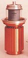
Boiling-cooled anode of a large transmitter tube

Air-cooled anode of a small transmitter tube. The left ring is the connection of the screen grid

The radiation-cooled transmitter tube 3-500 C with 500 W power loss has an anode made of graphite


The potential difference between anode and cathode accelerates the electrons emitted by the cathode: electrical energy is converted into kinetic energy of the electrons. If this stream of electrons hits the anode, the kinetic energy is mainly converted into thermal energy, but to a lesser extent also into light radiation (see above under the anode ) and, at higher operating voltages, into X-rays . The resulting heat must be dissipated so that the tube is not thermally destroyed. Depending on the design, it is not possible to dissipate any amount of energy per time, which is called the maximum anode power loss .
Performance comparison
The following table shows the structure of the anode and the maximum specific load capacity using the example of transmitter tubes for different types of cooling.
Type of cooling Anode type Max. specific
load capacityradiation Graphite, molybdenum 10 W / cm² Compressed air External anode made of Cu with cooling fins 50 W / cm² Water or oil cooling External anode made of Cu, surrounded by coolant 100 W / cm² Evaporative cooling External anode made of Cu, water is evaporated 500 W / cm²
Radiant cooling
With low powers, tubes are always cooled by radiation . The system is housed well insulated in a vacuum without any contact to the outside, heat can only be emitted through radiation. In order to radiate the power loss as effectively as possible, anodes and grids are provided with cooling fins or cooling fins, especially in the case of power tubes. A suitable dark material with a large surface (for example graphite or P2 iron) helps to increase the emissivity . Nevertheless, the power that can be radiated is very limited.
The control grid in the immediate vicinity of the hot cathode must remain particularly cool so that it does not emit any electrons. The retaining bars are therefore made of thermally highly conductive material (often copper with nickel plating) and also have cooling tabs at the end. In addition, the molybdenum grid wires can be gold-plated, since gold in conjunction with barium evaporated from the cathode increases the work function.
Radiation cooling is also found in X-ray tubes with a rotating anode , where the rotation ensures heat distribution, in that the incident electron beam only ever heats a small part of the anode that is moved by an electric motor. This partial area can then cool down again outside the beam spot until one revolution has been completed.
Other cooling methods

Transmission tubes with high output are cooled with water or another cooling medium , while transmission tubes with medium output are air-cooled (increased air cooling with fans). With this you can transport several hundred times more power than with radiation cooling.
In these tubes, the anode is made of solid copper and protrudes from the housing or a cooling medium flows through it inside. Compared to radiation cooling, this allows significantly higher power densities on the anode. The other electrodes, such as the screen grid, can also be cooled by conduction if they are disc-shaped .
Evaporative cooling is always used for maximum performance .
lifespan
Despite their high tolerance for brief excesses of electrical limit values, electron tubes have a shorter service life than semiconductor components. In power engineering in particular, tubes are consumable elements, while the original pre-tubes can often be found in receivers from the 1950s. Tubes have manufacturing-related tolerances in the double-digit percentage range, in some circuits a tube with far different parameters works better, in others less. In the field of high-end audio amplifiers, tubes are often replaced much earlier than is necessary for measurement technology.
The tube socket / tube socket construction, which was initially complex and, above all, problematic at very high frequencies, demonstrates the need for simple replacement.
The lifespan of an electron tube when operated within the limits is determined by the following factors, among other factors:
Interlayer formation
The electrochemical processes in the oxide cathode are the decisive factor limiting the service life. Especially when the tube is heated, but no anode current flows for long periods of time, a so-called intermediate layer forms between the cathode support and the oxide layer, which drastically reduces the emissivity of the cathode.
This intermediate layer has semiconductor character and occurs preferentially in tubes with a high slope density (mA / V cm 2 ). Optical investigations showed this layer as a glass-like layer formed directly on the cathode sleeve, the equivalent circuit diagram of which is a parallel connection of capacitor and resistor: It is frequency-dependent. By measuring the slope at different frequencies (e.g. 10 kHz vs. 10 MHz), a qualitative statement can be made about any intermediate layer formation. In the case of a cathode without an intermediate layer, the slope values are the same. Measured values are in the range around 80 Ω or around 1.5 nF.
This intermediate layer can be regenerated to a limited extent by targeted, careful overheating with a simultaneous high cathode current. See section Regeneration .
Removal of cathode material

The emissive material of the cathode can slowly peel off over time. On the one hand, this can be caused by very strong overload moments, which can occur, for example, when the tube is heated up with anode voltage already applied. On the other hand, there is constant evaporation in the tube. However, this process is very slow under normal operating conditions and only becomes noticeable after several tens of thousands of operating hours. As a result, grid emissions can occur even before the cathode becomes numb.
Lattice emission
A consequence of material evaporating from the cathode and precipitating on the control grid can be grid emission . The control grid emits electrons, which makes it more positive, increases the anode current and shifts the operating point to such an extent that distortions and / or thermal overload occur. This causes the control grid to heat up even more and emit more electrons. Circuits in which the grid bias is supplied via a particularly large resistor (1 megohm or greater) are particularly susceptible. Then just a few microampere grid emission current are enough to cause a failure.
vacuum
A tube's vacuum can deteriorate for two reasons: outgassing of materials inside the tube, which depends on the quality (purity) of the materials, and ingress of gases through the bulb.
Due to the operating temperature of an electron tube, the temperature of the glass bulb or the ceramic-metal welds between switched on and off changes by around 100 K; with power tubes, the temperature difference can even reach 150 K. Sometimes a large number of switching operations on and off is accompanied by the formation of hairline cracks in the piston. Most gases (oxygen, nitrogen, carbon dioxide and so on) can initially be adsorbed by the tube's getter . In the case of glass tubes, the getter enables the vacuum to be checked visually: as long as the silver coating on the inside of the bulb is still clearly visible, the vacuum can be considered sufficient. If, on the other hand, it has disappeared or has become milky-transparent, there is air in the glass bulb. If there is sufficient gas pressure, the filament oxidizes: it burns. The tube is now permanently destroyed.
The deterioration in the vacuum initially results in changes in the electrical properties. In this way, glow discharges can arise in a space that is no longer completely gas-free , which increases extremely quickly to arc discharges , especially in the case of output tubes, because high-ohm external resistances are not necessary in terms of circuitry . These may affect other components (mains transformer, rectifier tube, output transformer). However, if the circuitry ensures that the internal flashover only burns briefly and does not cause any consequential damage, the vacuum in a tube can be improved again by the metal vapor and its gas adsorption capacity. This phenomenon is observed or used particularly with transmitter tubes.
Long-life tubes
Special tubes are used wherever a very large number of tubes work together in an electronic system (electronic computing devices, telephone transmission systems and so on), only tubes with very narrow tolerances can be used, or where special requirements are placed on reliability. Different types of special tubes have been developed depending on the intended use. Tubes for electronic computing systems have a special cathode that has little tendency to form intermediate layers. In addition to other requirements, tubes for military use are often designed for high accelerations. The lifespan of these special tubes is generally given as 10,000 hours.
Special tubes are marked differently by the manufacturers. The system designation is often interchanged with the digits, so an ECC88 in the special variant becomes an E88CC. Valvo has also established various series here, differentiated by color (red series, blue series, and so on) which in turn have special properties (more solid system structure, cathode without interlayer, and so on).
Today, special tubes are among the sought-after and therefore comparatively expensive electron tubes.
Regeneration
A common cause of failure of electron tubes are deaf cathodes, that is, their electron emission decreases. Such cathodes can be regenerated to a certain extent. For this purpose, the cathode is deliberately overheated for certain periods of time, while a limited anode current flows at the same time. The aim is to reactivate the cathode so that the tube works again for a while.
In the case of display tubes that are weak due to age, such as magic eyes , regeneration is generally not possible, since the reasons are not to be found in a weak emission of the cathode, but rather appear almost exclusively in the fact that the phosphor becomes numb. There are ways to achieve a higher luminosity again by massively increasing the anode voltage.
For picture tubes , picture tube regeneration devices were previously available, which simplified the regeneration process.
Furthermore, deaf picture tube cathodes were permanently overheated in order to remain functional for a certain time.
Today's hot cathodes of picture tubes and other cathode ray tubes have a service life that usually exceeds that of the device.
Loose contacts
The electrical connections within the electron tube can lose secure contact due to mechanical effects such as vibrations. Another reason for malfunction can be mechanical problems with the contacts of the tube in the socket. In order to check whether there is such a loose contact , it is helpful to act mechanically on the tube with a special chipping hammer during operation .
Tube gauges
In order to check the condition of an electron tube, tube measuring devices were developed in the marriage of the tubes . They can be used to determine essential parameters such as current consumption, steepness or grid currents.
literature
- Heinrich Barkhausen : Textbook of the electron tubes . 4th edition. S. Hirzel Verlag, Leipzig 1937 ( raumladen.files.wordpress.com [PDF; accessed on November 6, 2014]).
- Friedrich Benz: Introduction to radio technology . 4th edition. Springer-Verlag, Vienna 1959.
- Fritz Kunze, Erich Schwendt: Tube pocket table . 15th edition. Franzis, Poing 2006, ISBN 3-7723-5454-8 .
- Eduard Willi: Swiss electron tubes 1917–2003 . Self-published by Willi, Russikon 2006, ISBN 978-3-03300552-5 .
- F. Bergtold: Röhrenbuch for radio and amplifier technology . Weidmannsche Buchhandlung, Berlin 1936.
- Ludwig Ratheiser: The great tube manual . Franzis-Verlag, Munich 1995, ISBN 3-7723-5064-X .
- Ludwig Ratheiser: Radio tubes - properties and application . Union Deutsche Verlagsgesellschaft, Berlin 1936.
- Herbert G. Mende: Radio tubes, how they became, what they do, and other things that are not in Barkhausen . Franzis-Verlag, Munich 1966.
- Gerhard B. Salzmann: On the history of the RV12P2000 . Rüdiger Walz, Kelkheim 1994, ISBN 3-9802576-2-2 .
- Ernst Erb: Yesterday's radios . 4th edition. Funk Verlag Bernhard Hein e. K., Dessau-Roßlau 2009, ISBN 978-3-939197-49-2 .
- From the Philips Technical Library:
- Technical & Scientific Literature Department: Data and Circuits of Receiver and Amplifier Valves . In: Series of Books of Electronic Valves . tape II . NV Philips' Gloeilampenfabrieken (Philips Industries), Eindhoven, NL 1949 ( online [PDF; 26.0 MB ]).
- Technical & Scientific Literature Department: Data and Circuits of Receiver and Amplifier Valves, 1st Supplement . In: Series of Books of Electronic Valves . tape III . NV Philips' Gloeilampenfabrieken (Philips Industries), Eindhoven, NL 1949 ( online [PDF; 14.0 MB ]).
- Technical & Scientific Literature Department, NS Markus, J. Otte: Data and Circuits of Radio Receiver and Amplifier Valves, 2nd Supplement . In: Series of Books of Electronic Valves . IIIa. NV Philips' Gloeilampenfabrieken (Philips Industries), Eindhoven, NL 1952 ( online [PDF; 30.0 MB ]).
- Technical & Scientific Literature Department, J. Jager: Data and Circuits of Television Receiver Valves . In: Series of Books of Electronic Valves . IIIc. NV Philips' Gloeilampenfabrieken (Philips Industries), Eindhoven, NL 1953 ( online [PDF; 15.0 MB ]).
- Werner Espe: Materials science of high vacuum technology . 1: Metals and metallically conductive materials. VEB Deutscher Verlag der Wissenschaften, Berlin 1957.
- Werner Espe: Materials science of high vacuum technology . 3: auxiliary materials. VEB Deutscher Verlag der Wissenschaften, Berlin 1957.
- Horst Rothe: Electron tube physics in individual reports . Franzis Verlag, Munich 1953.
Patents
- Patent GB190304168 : Improvements in the Method of and Means for Obtaining Uni-directional Current from a Single-phase or Poly-phase Alternating Current Source. Registered on February 21, 1903 , inventor: Peter Cooper-Hewitt.
- Patent DE179807 : Cathode ray relay. Published March 4, 1906 , inventor: Robert von Lieben.
- Patent US841387 : Device For Amplifying Feeble Electrical Currents - The De Forest -Triode. Registered on October 25, 1905 , inventor: Lee de Forest.
- Patent GB190424850 : Improvements in Instruments for Detecting and Measuring Alternating Electric Currents. Registered on November 16, 1904 , inventor: John Ambrose Fleming.
Web links
- Tube basics
- Page about electron tubes by H.-T. Schmidt
- Large data sheet collection
- Misunderstandings about tubes
- Tube comparison lists, data sheets, circuit diagrams
- Tube production by hand (Flash Video - 17 minutes)
- World Tube Audio, Tube Directory
Individual evidence
- ^ Felix Auerbach: History of the development of modern physics . J. Springer, Berlin 1923. p. 263
- ↑ Patent US307031 : Electrical Indicator. Registered November 15, 1883 , published October 21, 1884 , inventor: Thomas A. Edison ( PDF ).
- ↑ Patent GB190424850 : Improvements in instrument for Detecting and Measuring Alternating Electric Currents. Registered on November 16, 1904 , inventor: John Ambrose Fleming.
- ^ Homepage to Robert von Lieben
- ↑ Patent DE179807 : Cathode ray relay. Published March 4, 1906 , inventor: Robert von Lieben.
- ↑ Andreas Stiller: Röhrenradau. 100 years of dispute over electronic amplifiers. In: c't . tape 6 , 2006, p. 67 ( c't archive ( memento from February 28, 2009 in the Internet Archive )).
- ↑ Patent US841387 : Inventor: Lee de Forest: "Device For Amplifying Feeble Electrical Currents" - The De Forest -Audion tube, signed on 25 October 1906
- ↑ Triode type A
- ^ Pliotron, Udo Radtke Collection
- ↑ Patent DE293460 : Arrangement for cathode ray relays , which act as amplification relays . Published August 23, 1914 Applicant: Wireless Telegraph Society.
- ↑ Patent DE300617 : Vacuum amplifier tube with hot cathode and auxiliary electrode. Registered on June 1, 1916 , applicant: Siemens & Halske.
- ^ HJ Round: Direction and Position Finding . In: Journal Inst. Elec. Closely. lviii, no. 58 , 1920, p. 224-257 .
- ↑ In 1919, Dr. Eduard Schrack in Vienna Währing a production facility for his radio tube "Tritoron" accessed on September 16, 2010
- ↑ Circuit diagram Ducretet RM5 from 1926, Link (PDF)
- ↑ The Loewe 3NFB tube - analysis of a multiple tube Link (PDF; 170 kB)
- ↑ A MiG-25 that was flown to Japan by a deserter on September 6, 1976 . The incident gave western agencies deep insights into the technology of the then new MiG-25.
- ↑ USA from 1932.
- ↑ Explanations of the local pipe from PDF-S. 13
- ↑ Funk-Technik, issue 24/1947
- ↑ War Department Technical Manual TM11-235, Fig. 15, p. 13
- ↑ AF7 in the radio museum
- ↑ EF12 in the Radio Museum
- ↑ Wilfried Meyer: Urdox resistors Technical use in: Archive for Technical Measurement, Oct. 1938
- ↑ § 5 of the Ordinance on Protection against Damage by X-rays ( Memento from March 1, 2018 in the Internet Archive )
- ↑ http://www.nva-radar.de/infos/030512-Kenntnis%20der%20Strahlenexposition%20an%20P-15%20mindest%20ab%202002.pdf data of the GMI-90 in the radio measuring station P-15 of the NVA, Information on the 2003 Radar Commission report
- ↑ Formation of streaks in electron tubes
- ↑ Discussion about mirror formation in the forum of the Radio Museum
- ↑ Tube project TU Berlin ( Memento from August 4, 2007 in the Internet Archive )
- ↑ Data sheet EQ80 Enneode (PDF; 622 kB)
- ↑ hts-homepage.de
- ↑ Ludwig Ratheiser: The large tube manual. Franzis Verlag, Poing, ISBN 978-3-7723-5064-1 .
- ↑ tubedata.info Frank's electron tube page
- ↑ Herbert G. Mende: Radio tubes. Franzis-Verlag, 1952, p. 123.
- ↑ Exemplary data under SQ Tube ( Memento from May 17, 2013 in the Internet Archive ) p. 11
- ↑ Regeneration of magical eyes in Jogi's tube shack
- ↑ Easy regeneration of B / W picture tubes ( Memento from April 12, 2009 in the Internet Archive )