
steam train


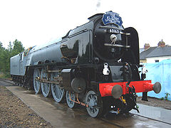
A1 60163 Tornado ( LNER class A1 , replica 2008)


Superheated steam express locomotive of the Kgl. Prussian State Railways, exterior view

Superheated steam express locomotive of the Kgl. Prussian State Railways, sectional view


The steam locomotive (short steam , as metaphor also Dampfross ) is a design of the engine , of water vapor is driven. In addition to the widespread standard design with steam generator and piston steam engine with crank drive chassis, there are special designs such as fireless locomotives , gear steam locomotives, those with single-axle or turbine drives, condenser and high-pressure locomotives.
Steam locomotives were the first self-driving, machine-driven rail vehicles and dominated rail transport from its inception until the middle of the 20th century. Steam locomotives were also responsible for the rapid development of transport technology that was now beginning as well as national and international trade . With the advent of more modern drive technologies, steam locomotives were gradually replaced by diesel and electric traction vehicles because of their comparatively poor efficiency and because of the high operating, maintenance and repair costs . The construction of new steam locomotives has been an exception since the last quarter of the 20th century.
Technology of the steam locomotive
Steam locomotives were built in a vast number of different types and variants. The following section mainly describes the European standard design of the 20th century with a classic tubular boiler and piston steam engine. Different versions can be found in the article steam locomotive (type) .
Overall constructive structure
 |
Assemblies of a tender locomotive with the wheel arrangement 1'C1 ':
|

Steam locomotives of the standard design mainly consist of the steam boiler , in which steam is generated from water using the heating energy of the fuel, a piston steam engine that converts the pressure energy of the steam into mechanical kinetic energy, the chassis with frame and wheel sets and a driver's cab for operating the machine. The necessary fuel and water supplies are carried either on the locomotive itself ( tank locomotive ) or in a vehicle that is permanently coupled to it, the tender ( tender locomotive ).
The steam boiler with the fire box built into it , the steam engine and the driver's cab are mounted on or on the locomotive frame. This frame is supported by the drive wheel set , the coupled wheel sets connected by coupling rods and often additional non-powered wheel sets . The piston steam engine usually has two, but also three and four cylinders , which are attached laterally on the outside of or (and) inside the frame. The oscillating movements of the piston rods are transmitted to the crankpins of the wheel sets by means of the connecting rods and thus converted into a rotary movement.
Steam generation and energy conversion
In steam locomotives, thermal energy is converted into kinetic energy . Usually these are an open system, in which the steam is released into the atmosphere as exhaust steam after the work in the steam cylinders . In the case of exhaust machines, it is first passed through a blowpipe to fan the fire . In the case of condensing locomotives , on the other hand, the exhaust steam is directed to a condensing tender , where it is liquefied again and available again as boiler feed water .
Lighting
Steam locomotives obtain their primary energy from the combustion of the fuel they carry . In most cases these are coal or heavy oil , but also wood , coal dust , peat and mineral oil . The boiler heated in this way generates the steam for the steam engine from water . Steam locomotives usually have a grate furnace with a flat fire bed. Coal dust, heavy or mineral oil do not require a grate system, but are burned in a special fire box with suitable burners . Heavy oil must be preheated with heat exchangers and is atomized and burned in the burner with a jet of superheated steam. Coal dust is brought in with compressed air or sucked in by the negative pressure in the completely closed fire box. Shunting locomotives with (additional) electric boiler heating are known from Switzerland with its many electrified routes .

The fresh air supply for the combustion takes place through adjustable air flaps on the ash pan , in which the combustion residues are also collected when burning solid fuels. For a better air supply when the ash box is full, ash boxes of the type Stühren are installed in modern Reko locomotives , which allow air to be supplied directly under the grate, regardless of its filling level. With other types of firing, the required air is introduced through special pockets, slots or through the burners (pulverized coal firing).
The blowpipe installed in the smoke chamber, developed by Trevithick , is indispensable for fanning the fire and complete combustion . The machine exhaust steam is fed through a nozzle, the blowpipe head, into the chimney. The exhaust steam jet completely fills the cross section of the chimney and, according to the injector principle, carries away smoke and pyrolysis gases . This creates a negative pressure in the smoke chamber, which propagates through the smoke and heating pipes to the fire box. The fresh air flowing in through the ash pan and the grate provides the necessary fire fanning. It is advantageous that this system regulates itself because more exhaust steam is blown out with higher steam consumption and thus a higher negative pressure is created. Because the exhaust steam from the steam engine is only available while the vehicle is in motion, an auxiliary blower is also installed to keep the fire going when the vehicle is stationary or when it is idling . This consists of a pipe ring with fine bores placed centrally around the blowpipe head and, if required, is supplied with wet steam directly from the boiler. Before the introduction of the auxiliary blower, steam locomotives were uncoupled and moved back and forth during longer idle times in order to maintain the desired boiler pressure. An absolutely airtight smoke chamber and tight pipe penetrations are required for optimal fire fanning and complete, economical combustion.
A spark arrester is built into the smoke chamber so that no larger pieces of embers or combustion residues can get through the chimney during a strenuous journey. This consists of a wire mesh, which completely encloses the lower part of the chimney protruding into the smoke chamber and the blowpipe head. A baffle plate suspended from the wall of the pipe ensures that the device cleans itself.
Special designs of steam locomotives that are not equipped with this system (turbine and condenser locomotives) have specially adjustable induced draft fans to fan the fire. In order to increase the thermal efficiency of steam locomotives, the Austrian Adolph Giesl-Gieslingen improved the classic induced draft system considerably in 1951 with the Giesl ejector named after him . The result was fuel savings of eight to twelve percent.
Steam boiler


A large-capacity water boiler with many heating pipes is best suited for generating the required steam under the constantly changing operating conditions in railroad operations. Such a boiler has a large evaporation surface and is insensitive to irregular steam withdrawals and the associated pressure and water level fluctuations. The classic steam locomotive boiler consists of the standing boiler with the fire box completely surrounded by a water jacket , the long boiler , which usually consists of several boiler sections, and the smoke chamber with built-in induced draft system and chimney for fanning the fire. This construction principle is the so-called Stephenson tube boiler .
In the fire box, the heat generated during combustion is transferred directly to the fire box walls and the boiler water circulating behind them. One speaks here of the radiant heating surface . The resulting hot flue gases then flow through the heating pipes built into the long boiler and transfer the heat to the pipe walls. The sum of the area of the pipe walls forms the pipe heating surface . In the case of superheated steam locomotives, smoke pipes with a significantly larger diameter are installed in addition to the heating pipes. The superheater elements, in which the steam generated in the boiler is dried and further heated, are inserted into these smoke tubes . The superheated steam , which is now up to 400 degrees Celsius in locomotive operation, ensures a higher efficiency of the steam locomotive engines due to its better condensation and expansion behavior.
To extract steam that is as dry as possible and to avoid overflowing boiler water, there are one or two steam domes on the top of the long boiler . The wet steam regulator responsible for regulating the steam supply to the machine is usually built into a steam dome . The generated wet steam with a temperature of 170 to 210 degrees Celsius depending on the boiler overpressure is a mixture of steam and the finest water droplets.
German steam locomotives usually work with boiler overpressures of 12 to 16 bar . The production of medium-pressure locomotives with 20 to 25 bar and high-pressure locomotives with up to 400 bar boiler pressure were mostly limited to a few copies because of the material properties that were not controllable at the time. Many of these machines were later converted to normal pressure locomotives. The boiler pressure is limited by at least two boiler safety valves of different designs, which blow off steam into the open environment in a controlled manner when the maximum permissible pressure is exceeded.
Modern steam locomotives have a more efficient combustion chamber boiler . Special designs such as the flame tube boiler , the Brotan boiler or the corrugated tube boiler could not prevail.
Piston steam engine of the steam locomotive
Cylinder and piston

In the case of locomotives with a wet steam regulator, the steam extracted in the steam dome first passes through the regulator valve and from there enters the wet steam chamber of the steam collecting box in the smoke chamber. From here it is fed into the superheater tubes, where it is heated to temperatures of around 370 degrees Celsius. The superheated steam then reaches the superheated steam chamber of the steam collecting box and from there into the main inlet pipe of the steam engine. If a superheated steam regulator is used instead of the wet steam regulator, the superheated steam from the superheated steam chamber of the steam collecting box reaches the main inlet pipe of the steam engine via the superheated steam regulator valve. The steam expands in the cylinders of the piston steam engine, thereby moving the pistons . In this way, the thermal energy stored in the steam is converted into mechanical energy.
Steam locomotives are double-acting because they can be reversed and because a locomotive must be able to start from any position with full tractive effort. The pistons in the cylinders of the steam engine are alternately supplied with steam from the front and rear. The reciprocating movement of the pistons is transmitted to the drive wheels via the drive rods and thus converted into a rotating movement.
So that the steam locomotive can start moving even when the crank position is dead center , the crank pins of the opposite wheels on an axle are offset from one another. The offset angle for two- and four-cylinder machines is a quarter turn or 90 °, for three-cylinder machines it is usually a third of a turn or 120 °.

1 - counter crank,
2 - swing arm,
3 - control rod,
4 - hanging iron,
5, 6 - throwing lever ,
7 - swing arm ,
8 - slide
push rod , 9 - handlebar attachment on the cross head,
10 - slide rod guide ,
11 - Handlebar rod,
12 - advance lever,
13 - slide rod,
14 - piston slide
control
The control system consists of a rocker arm , counter crank, slide pusher rod, advance lever, cross head, control cylinder with piston slide, steam cylinder and control rod.
The adjustment of the power and thus the steam consumption to the changing operating conditions is realized with an additional control . Its main components are the slide cylinders with slide pistons attached to the working cylinder. They control the side and amount of steam entering the working cylinder. In contrast to flat slide valve controls, piston valve controls have an internal flow.
During operation, the control spools alternately advance the working piston movement. The slide opens the cylinder, steam flows in. After about a third of the piston travel, the slide blocks the inflow. The energy present in the steam drives the piston through expansion to its dead center. The continuous, changing slide movement is caused by a control linkage that is connected to the drive linkage. By variably setting the control, z. B. achieve a high starting tractive effort through long steam filling over the piston path. By reducing the filling times at high speed, the steam consumption per piston stroke is reduced to the necessary level. Since the steam expansion is now used more, the energy efficiency improves.
The driver sets the control from the driver's cab with a hand crank or with a control lever, which is secured in the respective position by detents, whereby the pivot point of the control linkage and thus the travel of the slide is adjusted on the swing arm. In particular with newer and articulated locomotives, the reversing is actuated with compressed air. The second control element besides the slide adjustment is the regulator valve on the driver's cab, which adjusts the steam pressure to the cylinders.
The control thus has two end points of the setting: on the one hand, the fully configured control with a steam pressure at which the wheels of the locomotive do not just spin, which is important when starting. On the other hand, the minimally designed control with full steam pressure in order to achieve the economic optimum with the maximum possible expansion in the cylinders.
In between there are numerous operating states, whereby it depends on the experience and the instinct of the train driver to find the point of optimal energy utilization with the control setting. The direction of travel can be reversed by reversing the filling sequence; a steam channel set in opposite directions while driving can be used for braking (counter-steam brake ).
landing gear
Wheel sets, single-axle and two-axle drive


Only in the rarest of cases do railway vehicles have wheels running loosely on their axles. The two wheel centers are almost always mounted on a wheelset shaft (incorrectly also called axle shaft) so that they cannot rotate. In classic steam locomotive construction, the wheel bodies were mainly designed as wheel stars (spoked wheels). Wheel tires with the actual running profile ( flange , tread) are shrunk onto the wheel stars . This complete unit, which is also completed with axle bearings on wagons , is called a wheel set . In the case of steam locomotives, a distinction is made between driving, coupling and running wheel sets. Driving and coupled gear sets are driven gear sets. While the drive wheel set to absorb the forces transmitted by the drive rods is particularly solid and is firmly mounted in the locomotive frame, coupling wheel sets can be designed to be lighter and laterally movable in the frame. The linear movement generated by the steam engine is converted into a rotary movement on the drive wheel set as an element of the crank mechanism. The power flow takes place from the drive rods to the drive pins or the wheelset shaft designed as a crankshaft and via coupling rods to the coupling pins of any coupled wheel sets. As a special design, the laterally movable outer coupled wheel sets were driven by gear drives in some slow-moving, multi-axle locomotives to improve arcuate mobility. The so-called Luttermöller axle drive only proved itself to a limited extent due to its complicated structure and the high need for repairs.

While the steam locomotives in the early days managed with one or two coupled wheel sets, the increase in size and mass of the locomotives that came with the further development of the machines had to be countered by installing additional coupled or running wheel sets. This was the only way to ensure that the vehicle mass was evenly distributed across the road , depending on the permissible axle load . The size of the drive and coupled wheel sets was limited by the clearance profile and the structural design of the locomotive. Another criterion was the theoretically maximum possible piston speed of 7 to 9 m / s and the resulting speed of the drive wheel sets. Until then, it was believed that the necessary mass balancing of the crank mechanism could still be mastered. Experience has shown that speeds of up to 400 min −1 for wheel sets in conventional engines, in which the power is transmitted through drive rods and coupling rods, are considered manageable. In addition, the engineers expected massive problems with the mass balancing and the lubrication, especially of the parts moving under steam. The maximum upper limit of 2300 mm running circle diameter was considered to have been reached on modern steam locomotives in Germany with the locomotives of the 05 and 61 series . The three-cylinder 61 002 has been rebuilt as 18 201 , and since 1970 02 0201.
Steam locomotives with two steam cylinders are usually driven by a drive wheel set (traditionally called a single-axle drive ). In the case of locomotives with three (triples) or four cylinders (quadruplets), in addition to the drive on a drive wheel set (referred to as a single-axle drive by Borries in the case of compound locomotives ), a drive on two drive wheel sets ( two-axle drive , also known as the de Glehn type two-axle drive for compound engines )
To achieve a higher tractive effort , powerful freight locomotives have many coupled wheel sets with relatively small wheels. This was made possible by the Austrian designer Karl Gölsdorf . He proved that smooth running is possible thanks to side-shifting coupling gear sets. The first five-coupler he developed was the successful kkStB series 180 . Just like the maximum wheelset load, the number of wheel sets that can be coupled in a rigid frame is also limited. In practice, machines with six coupled wheel sets supported in a frame were implemented, for example in Germany the Württemberg series K , the later series 59 of the Deutsche Reichsbahn. The Bulgarian State Railways had two series with the axle sequences F and 1'F2 ' in use, and six- couplers also ran on Java. An unsuccessful attempt with a seven-coupler was only attempted once with the SŽD series АА 20 . With multi-part frames and other special solutions, attempts were made to accommodate as many coupled wheel sets as possible. The best known articulated locomotive types are the Mallet , Meyer , Garratt and Fairlie types .
High-performance boilers reach lengths and dimensions that cannot be carried by the coupled wheel sets alone. In addition, the running properties of machines with excessively large overhanging masses are no longer satisfactory at higher speeds. This was noticed very early on with Stephenson's long boiler machines. It was therefore started to equip the locomotives with additional, non-powered wheel sets . This enabled the overhanging mass of the smoke chamber and cylinder blocks as well as the standing boiler to be effectively reduced. Rear wheel sets also make it possible to arrange the fire box and ashtray behind the coupled wheel sets, making them larger and more powerful. To improve the curve run, the wheel sets were very soon laterally movable and later radially adjustable in various designs. Reset devices improve the guidance of the vehicle in the curve, especially if the managers are distributed over several wheelsets. For this reason, a leading running bogie was used, especially for high-speed machines , or a radially adjustable wheel set was combined with the first, laterally shiftable coupled wheel set in a Krauss-Helmholtz steering frame . Because of the space required for the ash box, the rear wheel sets of tender locomotives are mostly tiller-less " Adam axles " or externally mounted delta towing frames . In tank locomotives , identical running characteristics in both directions are usually more important, which is why they often have a symmetrical running gear. In this case, the steering frame under the ash box is accepted.
Mass balancing

The reciprocating masses of the pistons as well as the piston, drive and coupling rods cause considerable imbalances when converted into the rotary motion , which lead to the locomotive running unevenly. The piston movements of a two-cylinder machine do not compensate each other because they do not work half a period, but a quarter period . With counterweights on the wheels, these forces can be partially, but not fully, compensated.
The unbalance caused by the rotating masses of the coupling rods and crank pins alone can be completely compensated for by counterweights, so that the problem z. B. does not occur in older electric locomotives with rod drive and an otherwise rotating motor. To compensate for the reciprocating masses of a piston steam engine, the counterweights have to be increased, which in turn leads to a renewed imbalance of the wheels. As a result, the rails can wear more heavily at certain points, and at high speeds there can even be a loss of wheel-rail contact, the so-called jumping of the wheels. A practical compromise in the design has emerged to compensate for only about 30 to 50% of the to-and-fro masses. At low speeds and with little demand for comfort, such as in freight transport, this was sometimes completely dispensed with.
Much more important, however, was the most extensive possible mass balancing in fast-moving locomotives. Here the problem has already been reduced by designs with more than two cylinders. Almost all high-speed locomotives therefore had engines with three or four cylinders.
Auxiliary units
Compressed air for the brakes

The brakes of steam locomotives mostly consist of block brakes on the coupling wheels, and in the case of high-speed machines also on the wheel sets, which were initially operated by hand, later with steam and from around 1900 mainly with compressed air . To generate compressed air, steam locomotives received a steam-operated air pump and various main and auxiliary air tanks for the compressed air supply.
Steam for train heating
In the further development, they were equipped with steam heating devices for comfortable heating of passenger coaches . The heating steam required for this was supplied to the individual heating systems from the locomotive via a heating line running through all the cars.
On the locomotive, wet steam is taken directly from the boiler using an adjusting valve and fed to the front or rear heating connection of the locomotive via a three-way valve that can be operated from the driver's cab or a switch valve (on standard locomotives). A safety valve (4.5 to 5 bar) and a pressure gauge complete the steam heating system on the locomotive.
Electric power supply
With the introduction of electrical lighting and later additional equipment such as train control , it became necessary to ensure a permanent and reliable electrical power supply. In the first attempts, small piston steam engines were used on the tender, but their regulation required too much attention from the stoker. The power supply only became practical with the introduction of centrifugal-regulated turbo generators . Because locomotives and wagons can be used freely, supply via axle generators prevailed in standard gauge passenger coaches. That is why regular-gauge German steam locomotives only have generators with 0.5 kilowatts for their own supply. The alternating voltages with frequencies of 500, 1000 and 2000 Hertz required for punctiform tension control were initially generated by additional windings. In closed networks, for example the narrow-gauge railways in Saxony, much larger turbo generators with an output of 10 kW are used. These supply the entire train of wagons.
Supply of operating materials
Water supply


During operation, the steam generated in the boiler from the feed water is expelled into the surroundings via the blowpipe and the chimney after work has been performed in the cylinders. A small part of the steam is consumed by the operation of the auxiliary machines such as an air pump or turbo generator or by steam losses due to open cylinder drainage valves or blow-off safety valves. The water level in the boiler must therefore be topped up at intervals or continuously depending on the load. The necessary for desserts water supplies are in water containers in the frame, the side of the boiler or in a Tender carried which is at water stations were filled. In the case of British tank locomotives in particular, there were also "saddle tanks" surrounding the long boiler.
For long uninterrupted journeys, such as that of the Flying Scotsman from London to Edinburgh or that of the New York Central Railroad , scoop pipes were used, which were lowered into special troughs in the middle of the track during the journey . The dynamic pressure created by the driving speed pushed the water through the pipes into the water tank of the tender.

For travel over long, arid stretches, for example in Argentina, the Soviet Union and later also in South Africa, condensation tenders were developed from the 1930s onwards , in which a large part of the exhaust steam after condensation could be used again to feed the boiler. In Germany, many class 52 locomotives for use in arid areas of the occupied Soviet Union were built with this technology. The condensation technology led to water savings of over 90%, but was not economical due to the high maintenance costs in areas with sufficient water reserves. Because the exhaust steam in condensate locomotives was not available for fanning the fire using a blowpipe, a special induced draft fan was required in the smoke chamber. A positive side effect during the war was that locomotives with a condensing device, especially in cold weather, could not be detected as easily by low-flying pilots because of the lower vapor plume.
Since the boiler is under pressure during operation, water must be topped up using special pumps. In the early days, this was mostly done with plunger or drive pumps. These were operated via an eccentric shaft or a crankshaft while the locomotive was in motion. The advantage of this method is that the delivery rate is approximately proportional to the distance covered. The flow rate was adjusted using a controllable bypass line. In the event of a long standstill or long journeys on steep inclines (increased steam requirement), the locomotive had to uncouple from the train and drive back and forth on a free track until the water level had reached the desired height again.
Modern steam locomotives must have two feed devices that work independently of each other in order to guarantee the minimum water level in the boiler, which is required for safety reasons. Piston feed pumps and injector pumps are used to fill the pressurized boiler . In piston pumps, a steam piston drives a small water piston that pushes the water into the kettle. In the case of the injector or steam jet pump, a jet of steam pulls water with it in the injector chamber, heats it up and pushes it into the boiler room.
The disadvantage of piston pumps is that the kettle is fed with cold water without preheating. At the feed water entry into the boiler, the temperature difference caused great thermal stresses in the material. From around 1900 the cold feed water of the tender was passed through preheaters (then surface preheaters , later mixed preheaters ) and preheated by the exhaust steam to around 80 to 90 degrees Celsius. Because cold feeding has to be avoided and preheaters only work while driving because of their dependence on exhaust steam, one of the two boiler feed devices must be a steam jet pump. In some countries, for example in the former USSR and in Poland, piston feed pumps were largely dispensed with and almost all locomotives were only equipped with jet pumps.
The correct water level in the steam boiler is also checked with two independently working sight glasses and taps from the heater of the locomotive. Too low a water level can lead to the kettle popping , and if the water level is too high, there is a risk of liquid water being carried away with subsequent serious damage to the superheater and the cylinders. Even the smallest amount of water causes a water hammer, especially in the cylinder : The space between the piston at dead center and the cylinder base is so small that the moving piston literally bursts off the cylinder cover due to the incompressible water in the cylinder .
The boiler feed water is treated to ensure the operational safety and economic efficiency of the steam locomotive. In particular, the formation of scale is prevented by the fact that the scale formers sink to the bottom (precipitate) in the boiler due to chemical additives and form a sludge-like layer there ( internal feed water treatment ). This sediment can be flushed out regularly through the blow-down valve , even while driving through the heater. In addition, the boiler is washed out at longer intervals.
Fuel supply

The fuels used (mainly coal , partly pulverized coal , wood , peat or different oils) are, as well as the water supply, in containers on the locomotive or train tender carried. As a rule, coal and other solid fuels were removed from the storage container by the locomotive heater manually or with a shovel and transported through the fire hole into the fire box .
To relieve the operating personnel, individual types of locomotives were also equipped with a mechanical charging system, the so-called stoker . The stoker systems mostly consisted of screw conveyors that conveyed the fuel from the coal container through pipes into the fire box. The screw conveyors were driven by a steam engine and could be precisely adjusted and reversed according to the fuel requirement.
In the case of oil firing, the preheated fuel is blown into the fire box through one or more burners (different arrangement and design depending on the type of construction) using an adjustable steam jet. Coal dust locomotives work differently, in which the finely ground coal dust is sucked in through the underpressure prevailing in the fire box, which is sealed on all sides, or blown in with compressed air. Occasionally was in memory steam locomotives , a red-hot iron in plants pig iron - slab deposited in the locomotive. With this heat, the locomotive could run for around two hours.
Guide to the locomotive

below the fire door, right in the middle the book timetable
Usually the cab of a steam locomotive is on the back of the frame behind the fire box. From there it is usually controlled by two people. The train driver has a fixed (seat) place on the side on which the control, regulator, driver's brake valve and additional devices such as the train control system are located. In continental Europe this is usually on the right, in the British Isles it was usually the left. From there he observes the route and the signals and controls the movement of the locomotive and the train. The heater primarily monitors and operates the firing and steam generation (fuel and water replenishment, pressure generation) by introducing fuel into the fire box. The stoker supports the driver in monitoring the signals through messages and confirmations. The seat for the stoker is on the opposite side of the cab from the driver.
Initially, the engine driver and stoker stood on an unprotected platform behind the fire box. With increasing speeds it became essential to add a windbreak and at least a short roof. The introduction of the closed driver's cab goes back to the railway pioneer Max Maria von Weber , who was familiar with the exertions of the locomotive driver and the stoker , especially in the winter season, and described it in his literary work. However, even then, seats were still viewed as “unheard of comfort” and as detrimental to the attention paid to route observation.
To create push- pull trains , experiments were carried out with signaling devices between the control car and the pushing locomotive, the functionality of which is reminiscent of the machine telegraph from seafaring. This was successfully practiced in 1936 with the streamlined trains of the Lübeck-Büchener Railway . However, this required a fixed train composition, which restricted the free use of the locomotives and was therefore not pursued any further.
Standards, development limits, special designs
Standard developments

The most widespread and simplest design of the steam locomotive had one to two wheel sets at the front and then three to five driven wheel sets coupled together and possibly a wheel set under the driver's cab. The steam engine consisted of a boiler with wet steam or superheated steam generation and two double-acting cylinders with single steam expansion.
The ELNA steam locomotives were built in Germany in the 1920s . The abbreviation ELNA stands for Engerer Locomotive Standards Committee . The locomotives should be able to be produced and operated more economically through standardization.
Under the name of standard locomotives, steam locomotives were developed and built for the Deutsche Reichsbahn from 1925 under the direction of the then design department at the Reichsbahn-Zentralamt, Richard Paul Wagner . It had been decided to replace proven regional railway locomotives with new developments. The main reasons were standardization and the use of uniform components. Not only components such as wheel sets, bearings, pumps, smoke tubes, cylinder blocks and fittings, but also materials such as boiler plates and frame materials were standardized. This meant that many parts were also interchangeable across series, which simplified storage and made maintenance cheaper. The first standard locomotive was the DR class 01 as the 2'C1 'h2. Both post-war German state railroad administrations built on these standardizations; however, the post-war constructions were created according to newer construction principles, especially in welding technology.
General limits
Sizes
The performance of the steam locomotive is determined by the piston diameter and stroke , steam pressure, number of cylinders, number of driving wheels and their wheel diameter. However, all of these parameters can only be changed to a limited extent.
The wheel diameter is decisive for the possible maximum speed due to the piston speeds that can only be controlled to a limited extent and the associated engine speeds. However, it cannot be increased at will without impairing the size of the boiler and thus the pulling force or exceeding the vehicle boundary. The to-and-fro masses in the crank mechanism cannot be completely compensated, especially in two-cylinder engines, which leads to uneven running, especially at higher speeds. In addition, large drive wheel diameters reduce the tractive effort and possible acceleration due to the less favorable lever ratios.
Most modern steam locomotives have boilers with an operating pressure of 16 to 20 bar. Steam generators with a higher steam pressure (up to 60 bar) required more complex maintenance work in the long term, which is why they could not be used on locomotives.
For structural reasons, the number of cylinders in standard types can only be increased to a maximum of four. There are triple and quadruple machines with simple steam expansion, in which all cylinders receive boiler steam, and compound machines with high pressure and downstream low pressure cylinders. With the compound principle, the thermal energy of the steam is better utilized, and three- and especially four-cylinder engines enable significantly better mass balancing.
However, since this increased maintenance costs, locomotives with two or three cylinders and only one expansion stage ultimately prevailed. Above all, railways in the USA, England and northern Germany, where coal was relatively cheap and readily available, did without the higher efficiency. France, Switzerland and the southern German railways, who procured composite locomotives until the end of steam traction or until the end of their independence, did the opposite. The DB also modernized thirty originally Bavarian four-cylinder composite locomotives to the 18.6 series in the phase of the beginning traction change.
Services

Under the Central European conditions, locomotives were built that reached top speeds of over 200 km / h in test runs ( Deutsche Reichsbahn - locomotive 05 002 and the British LNER locomotive Mallard ). Indexed outputs of up to 5300 HP (4000 kW) were achieved with compound machines ( SNCF 242 A1 , France). In terms of power-to-weight ratio (mass per power), the 240 P of the French SNCF, like the 242 A1 by André Chapelon , was considered the most powerful locomotive.
The world's largest steam locomotives were the mallet and triplex locomotives of American railways. Under the frame and tender, these locomotives had up to three independent two-cylinder engines. Practically all large and modern US steam locomotives had an output of 5000 to 8000 HP (4000 to 6000 kW), which was made possible by comparatively large dimensions and masses.
The locomotives of the class S-1b ("Niagara") of the New York Central carried trains with 22 Pullman express train carriages of over 1600 tons on the plain at 161 km / h in daily operation. In test drives, this load even reached 193 km / h. Today's IC and EC trains are only about half as heavy. The S-1b series also holds the record of monthly mileage for steam locomotives. Trains like the ones mentioned above, which traveled the 1,485-kilometer route from Harmon, NY to Chicago without changing locomotives, covered over 44,000 kilometers.
For the class S1 machine of the Pennsylvania Railroad , 193.2 km / h or 120 mph was specified as the regular, operational maximum speed, but the goal was not achieved, trains with a mass of 1000 tons at 100 mph or 161 km / h to transport.
The very labor-intensive maintenance of the steam locomotives (operation of the locomotive by two men, wash-out personnel and others), the very intensive and time-consuming testing and maintenance of the locomotive (washing the boilers every two days up to a maximum of weekly), the statutory inspections of the steam boilers due to the risk of boiler explosions and the parallel development of electric and diesel locomotives led to the decommissioning of steam locomotives on almost all railways in the world in the 1970s. But also the low level of efficiency , which was usually around eight to ten percent, and the pollution from carbon soot meant that the steam locomotives disappeared more and more from the scene. However, the structural possibilities of the steam locomotive had not yet been fully exhausted at that time.
Special developments
Higher requirements, favorable or less favorable conditions, have led to special designs of steam locomotives. The Crampton locomotives , which were very widespread in France and Germany at the beginning , the Mallet and Garratt locomotives that appeared later, as well as drive variants should be mentioned here. A comprehensive overview is listed under steam locomotive (type) .
business
For the operation of steam locomotives, a number of buildings and measures are necessary, which shape and shape their appearance in the time and on the railways that use steam locomotives. This included locomotive sheds , in particular round sheds , water towers and coaling systems , but also the large-scale clearing of the main line to prevent forest and field fires caused by flying sparks .
historical overview
The steam locomotive was the original and long prevailing type of locomotive. It was the first traction device that was able to combine greater performance with a compact design and thus brought about the successful spread of the railway system.
Forerunner developments
The development of the steam locomotive was based on several previous developments. The first stage was the steam engine invented by Thomas Newcomen , in which a flywheel returned the cylinder to its original position after each working stroke . The next step was when James Watt let the steam act alternately on both sides of the flask. Until then, the steam engines worked with only a slight excess pressure compared to the ambient atmospheric pressure. When Richard Trevithick developed a steam engine that worked at three to four times higher than atmospheric pressure, it became possible to build a powerful work machine that was compact enough to fit on a vehicle. This was done for the first time by Nicholas Cugnot in 1769 and also by Richard Trevithick in 1801 and 1803, who each built a street steam car . With the help of the steam engine, spatially unlimited travel was possible, and it was then only a short step to replace the steam-operated cable pull systems that already existed in the mines with a steam car placed on the rails.
First steam locomotives on rails


In 1804 Richard Trevithick built the first steam locomotive to run on rails. It turned out to be functional, but the cast iron rails, which were not designed for their mass, broke under this locomotive.
Around this time there were multiple attempts to develop steam locomotives in English mines in Cornwall and around the north-east English coalfield around Newcastle upon Tyne . a. by Timothy Hackworth from 1808, John Blenkinsop 1812, William Hedley 1813, George Stephenson 1814 and others. In 1825 the railway line between Stockton and Darlington , England, initiated by Edward Pease , was opened with a locomotive from George Stephenson and at the same time the first passenger transport was carried out with a locomotive-drawn train.
For the planned railway between Liverpool and Manchester , the famous Rainhill race was carried out in October 1829 , in which the most suitable locomotive was to be determined. Of the five participating "real" locomotives won The Rocket of Robert Stephenson 's race, which peaked at 50 km route at a maximum speed of 48 km / h - that was the decisive factor - survived as the only race without failure. Timothy Hackworth's “Sans Pareil”, also in the competition, had cylinders cast in Robert Stephenson's workshop, one of which exploded shortly after the start of the race - a rather “regular” failure at the time. On September 15, 1830, the railway between Liverpool and Manchester was opened, with both the victorious "Rocket" and the "Sans Pareil" were taken into operation.
In the United States , Colonel John Stevens demonstrated a steam-powered traction engine on an annular track in Hoboken , New Jersey , in 1826 . In 1830, Peter Cooper built the Tom Thumb, the first steam locomotive in America for a public railroad, and the DeWitt Clinton , the first scheduled US locomotive between Albany and Schenectady, went into service on September 24, 1831 at around 50 km / h. John Bull , made in England and shipped to America, should not go unmentioned either . It was also put into service in 1831, retired in 1866 and last put under steam in 1981, now 150 years old. It is one of the last originally transmitted machines from the early steam locomotive era.
The first railway line on the European continent with steam operation was the Saint-Étienne – Lyon line in France since 1831 . Belgium , whose first steam train opened on May 5, 1835 between Brussels and Mechelen , had the densest railway network on the continent until the middle of the 19th century.
In Germany and the German Confederation , the first steam locomotive to travel in June 1816 was a Blenkinsop-type machine, which was built by Johann Friedrich Krigar in the Royal Iron Foundry in Berlin, on a circuit in the factory courtyard. It was the first locomotive built on mainland Europe and the first steam-driven passenger transport, as onlookers could ride in attached wagons for a fee. It is on a New Year's plaque of the Kgl. Iron foundry from 1816 shown. Another locomotive was built in 1817 using the same system . They were supposed to be used in mine railways in Königshütte (Upper Silesia) and in Luisenthal (Saar) , but both could not be brought into an operational condition after dismantling, transport and reassembly. On December 7, 1835, the locomotive Der Adler drove for the first time between Nuremberg and Fürth on the Ludwig Railway . It was already the 118th machine from the Robert Stephensons locomotive factory and was patented with the type designation " Patentee ".

In the Austrian Empire in 1837 the first steam train ran on the northern line between Vienna-Floridsdorf and Deutsch-Wagram . The longest-serving steam locomotive in the world also runs in Austria: the GKB 671 from 1860 was never retired and is still used for special trips.
In 1838 the third Saxonia steam locomotive built in Germany was built at the mechanical engineering institute Übigau near Dresden , designed by Prof. Johann Andreas Schubert . The Beuth, built by August Borsig in 1844, is considered the first independently designed locomotive in Germany . The machine factory Georg Egestorff (later Hanomag ) delivered the first steam locomotive "Ernst August" to the Royal Hanover State Railways in 1846 . Henschel & Sohn in Cassel (spelling at the time) built its first Drache locomotive for the Friedrich-Wilhelms-Nordbahn in 1848 .
The first railway line across Swiss territory was the Strasbourg - Basel line, opened in 1844 . Three years later, in 1847, the Spanish Brötli Bahn from Zurich to Baden was the first Swiss railway line to open.
Further development steps
First attempts, successes and wrong turns
The connections between mechanics, thermodynamics and power transmission, which were often still not understood at the time, despite the pioneering achievements of the mechanical engineering companies, led to constructions that often reinforced a certain property, but lost sight of the overall connection between heat generation, boiler output, wheel arrangement and weight distribution.
The following overview deals more with the developments that ultimately led to the successful standard construction. The constructions that differ significantly from this are listed in steam locomotive (type) .
Trevithick's first machine had two sets of wheels , both of which were driven by a giant gear. According to the German wheel arrangement designation or counting system, this was a "B" locomotive. Stephenson's later “Locomotion” was also a “B” type with two driven axles, but in contrast to Trevithick, Stephenson provided the wheels with crank pins that were connected with coupling rods . This then became the most widespread multiple wheel set drive, which for the first time made it possible to cushion the locomotives and was later also used in the first electric and diesel locomotives . However, together with the standing cylinders, the introduction of the suspension required an increase in the harmful spaces .

Stephenson's "Rocket", built in 1829, was a step backwards in development, as it had only one driven axle in front and a smaller wheel set behind it (axle arrangement A1). Their advantage was the cylinders inclined by about 45 °. This arrangement reduced the harmful space in the cylinders required to compensate for the spring deflection and thus the steam consumption compared to the vertical cylinder arrangement customary at the time. In a later conversion, the cylinders were lowered even further. The single drive axle allowed larger drive wheels for higher speeds without major constructional difficulties, but it reduced the friction weight of the drive, which is important for the traction . The same constructive inadequacy was even further driven 15 years later with Crampton locomotives . The "Cramptons" had even larger drive wheels, which, for reasons of space, were attached behind the deep, heavy boiler under the driver's cab. The deep basin should cause a smooth run. This meant that the Cramptons had difficulties starting, because the low-load driving axle tended to skid. Once a Crampton locomotive got the train running, it could develop considerable speeds with its long and therefore powerful boiler, which was supported by up to three leading axles without damaging overhangs.
Timothy Hackworth already understood the connection between frictional weight and tractive force and built the “Royal George” as a three-coupler (wheel arrangement C) in 1827. Freight locomotives with three coupled wheel sets remained standard for decades.
The machine, which was delivered to Germany by Robert Stephenson in 1835 and called "Der Adler" was the first on German tracks, had only modest pulling power and maximum speed with one wheel set in front of and one behind the drive wheel set (axis arrangement 1A1) located in the middle under the boiler. This simple construction probably proved to be reliable in operation, because steam locomotives with only one driving wheel set were built for various German regional railways until the late 1860s; The Bavarian State Railways in particular remained loyal to the "1A1" for a long time.
America is taking over the pioneering role from England


A peculiarity of US-American railways were long stretches and a light superstructure that was laid with little care , which led to a restless running of the locomotives with the stiff two-axle running gear adopted from England. To counter these difficulties, Henry Roe Campbell developed and patented a locomotive with the 2'B wheel arrangement ( American Whyte notation 4-4-0), i.e. with a leading, two-axle bogie and two coupled axles , as early as 1836 . With the greater length and the small overhanging masses, this construction achieved smooth running even on a poor superstructure and, thanks to the radial adjustability of the running bogie, an equally good curve path. By 1884, 60 percent of all US steam locomotives had a 2'B n2 wheel arrangement and were known as the "American Standard" or "American" for short. As the train weights increased and the speeds increased, the tried and tested "American" was simply enlarged and reinforced in all components in order to meet the increased requirements.
From the "New York Central-4-4-0" number 999 with its 2.15 m high drive wheels it is reported that it was on May 10, 1893 with the four car "Empire State Express" between Batavia and Buffalo , New York , reached a speed of 112.5 mph (181 km / h). By the end of the 19th century, variations of the "American" had been built around 25,000 times in the USA. In Europe, this design was adopted with a more or less long delay. Before that, passenger locomotives with 1B and 1'B axles were built there, mostly with overhanging cylinders that adversely affected the running properties.
The end of the "American" era came in the 1880s with the increasing spread of the air brake invented by George Westinghouse around 1869 ( US patent 1872). Instead of the hand-braked trains, these powerful brakes made longer and heavier trains possible, for which it was no longer sufficient to simply build the 2'B larger. This led to locomotives with triple and quadruple coupled wheelsets.
In Europe, a deep and stable boiler position was initially preferred for faster locomotives, but this was unfavorable for the arrangement of further large coupled wheel sets. Essential impulses to overcome this fear of the high center of gravity came from the USA. Soon, new locomotives were built here with an increasingly higher boiler position, which allowed the use of several coupled wheel sets. The German engineer Ludwig Löw von und zu Steinfurth wrote in 1924 in his standard work on motor vehicles that one had to learn from locomotive construction:
“The pursuit of a low center of gravity is exactly the same mistake that locomotive technology suffered from years ago; In the past, the locomotive's boiler was placed as low as possible, but today it is so high that there is hardly a chimney on it. It is natural that an automobile with a high center of gravity falls over more easily than one with a low center of gravity, but an automobile almost never falls over. "
A further development step was the introduction of the compound machine principle in steam locomotive construction, after this had already proven itself on steam ships . Here, the tendency of the steam to expand after it has been discharged from a first working stage is used again in a second stage in a low-pressure cylinder. The Swiss Anatole Mallet applied for a patent for use on locomotives in 1874.

The principle was initially used on locomotives with two separate running and power units (" Malletloks ") by connecting the cylinder pairs in series. Later, the compound principle was also applied to single-frame locomotives, initially to locomotives with two cylinders. These were noticeable due to the visibly different cylinder diameters. After that, there was a change to four-cylinder compound locomotives, especially in express train service. In these locomotives, the first drive axle was designed as a bolster axle and thus a crankshaft and was driven by two high-pressure cylinders located within the frame. On the outside of the frame were the larger low-pressure cylinders that worked in the usual way on the crank pins of the second drive wheel set (two-axle drive type De-Glehn ). The third set of drive wheels that was usually present was connected to the two front ones by the usual external coupling rods. August von Borries , on the other hand, designed locomotives with the single-axle drive named after him, in which all four cylinders act on a drive wheel set. The higher load on the bolster axle is countered by a simpler mass balancing, and high and low pressure cylinders can be arranged more easily in one plane, which shortens the steam paths. Compound locomotives required a special starting device. This means that the low-pressure cylinder or cylinders also receive live steam when starting up; the machine works with simple steam expansion. If the machine is in motion, it is switched to composite effect.
With larger locomotives, the problem of arching rigid frame locomotives arose. In 1884, Anatole Mallet again patented the curvilinear locomotive design known today under his name with two engines, one of which can be rotated or moved sideways. As a result, a total of around 150 mallet locomotives were built for many German state railways towards the end of the 19th century . However, the mallet principle only reached its peak in the USA . While the mallet type was mainly used in Europe for smaller locomotives, it was also used there for very large locomotives, but in many cases only with simple steam expansion, i.e. without the composite effect of the engine groups. This avoided the weak point of mallets with compound engines in the form of separate high-pressure and low-pressure engine groups, namely the alternating skidding of both engine groups.

In order to improve the ability to move in curves, the flanges of the outer drive wheel sets were partially made in a weakened thickness in order to reduce the pressure on the locomotive in curved tracks. Weakened wheel flanges on the end wheelsets hardly guide the machine on the track, however, and the short guided length causes uneven running. Flanged drive wheel axles were also used to improve sheet travel. After preliminary investigations by von Helmholtz , the Austrian Karl Gölsdorf used laterally movable coupling axles for the first time in large rigid-frame locomotives. This basically solved the problem of large, high-performance rigid-frame locomotives being able to move around curves, partly in conjunction with wheel flange weakening and individual wheel sets without flange.
The last missing component for the modern steam locomotive was the development of the superheater , which made it possible to increase the steam temperature to such an extent that no losses due to condensation occurred during the expansion in the cylinder . Here the German engineer and mechanical engineer Wilhelm Schmidt took the decisive step with the invention of the superheater, with which the superheated steam with temperatures of 350 ° C could be produced operationally in the steam engine boiler. This enabled the thermal efficiency of the steam engine to be halved. In 1897 the first two locomotives (one S 3 and one P 4) with flame tube superheaters were delivered to the Prussian State Railways.
Development highlights

Another striking and successful development was the "Pacific" steam locomotive type with the 2'C1 'wheel arrangement or the American designation 4-6-2. It originated again in the USA and became particularly widespread when the train masses increased around 1910 due to wagons made of steel and could no longer be handled by the 2'B and 2'B1 types.
After a locomotive with the 2'C1 'wheel arrangement was delivered to New Zealand for the first time in 1901 by Baldwin in the USA , a locomotive with the same wheel arrangement was delivered to the Missouri-Pacific Railway in 1902 by Brooks, a later subsidiary of ALCO the name "Pacific" came from. It was also beneficial for the development and spread of the "Pacific" that at the same time the use of the superheated steam principle with superheater began, which with this type, together with the larger fire box and the longer boiler, led to a sudden increase in performance, which for a long time led to further developments Express locomotives were unnecessary. It is said that more than 10,000 locomotives with the "Pacific" axle arrangement were built in North America alone.

In the late 1930s and 1940s, the technical peaks of steam traction were reached with the most powerful, largest and fastest machines ever built, the huge US mallet locomotives and high-speed steam locomotives such as the German class 05 or the English A4 , which were used in Test drives each reached just over 200 km / h. Whereby the »Mallard« is attributed to the world speed record, although it reached 202 km / h with a seven-car train on a slope and was damaged in the process; the German 05 002 reached 200.4 km / h with four cars on a flat stretch without damage, according to which it should actually be entitled to the title of fastest steam locomotive if both had been tested under the same criteria.
Modern US-American freight steam locomotives had continuous outputs of up to 8000 PSi (6000 kW, C&O series H-8, PRR series Q-2), express locomotives had up to 6700 PSi (5000 kW, NYC series S-1b, " Niagara "). They were built to be extremely robust, because with the high train loads (10,000 to 15,500 tons in the heavy freight train service, 1000 to 1800 tons in the heavy express train service), the "flat out" operation was the order of the day. As an express locomotive stayed up to 2,840 km in front of the train (AT & SF - Class 2900, on the Kansas City - Amarillo - Los Angeles route), reliability and easy maintainability were paramount.
The locomotives most built in Germany were the 55.25-58 class and the German class 52 war locomotives . The class 55.25-58, Prussian G8.1 was built in 4995 copies and was thus the most popular regional railway steam locomotive, followed by the P 8 passenger locomotive with the 2'C h2 wheel arrangement, which had been produced by Berliner Maschinenbau AG and Linke-Hofmann Werke since 1906 3800 copies were built in Wroclaw , of which about 500 were delivered abroad. Most of these locomotives were completed between 1919 and 1924.
The German class 52 was a considerably simplified version of the class 50 freight locomotive with a 1'E h2 wheel arrangement, of which around 6,500 were built between 1942 and 1945 for the increased transport requirements in the Second World War . The series 50 and 52 together reached a number of about 10,000. In addition to the Prussian State Railways, it was only the railways of the Soviet Union that had different series of locomotives built in numbers of over 3000.
In Switzerland, the C 5/6 2978 was delivered unusually early, namely in 1917, the last steam locomotive in SBB history. The advancing electrification helped the electric locomotives to triumph.

The most modern steam locomotive in the world went into operation in South Africa in the early 1980s. A high-performance steam locomotive of the 25 NC series , the 25NC 3450, built in 1953 by Henschel & Sohn in Kassel, was selected for a special test program and major components were changed. In 1981 she got a Lempor induced draft system with two chimneys in the Salt River workshops in Cape Town, between which the preheater was installed. The fire box was converted to the Gas Producer Combustion System (GPCS) by the Argentine engineer Livio Dante Porta. Steam lines have been optimized to reduce flow losses. Engineer David Wardale was responsible for the entire renovation. The locomotive was given the new class number 26 , but kept its company number. The subsequent attempts then lasted two years. Result: drastic coal and water savings compared to the 25NC series as well as around 40% increase in output. The peak performance in test drives was about 4500 hp at 75 km / h and almost 5000 hp at 100 km / h. The continuous output of the machine is over 3000 HP. After the end of the two-year test phase, the locomotive was put into regular passenger and freight train service, in a red paint scheme, which soon earned it the name "Red Devil", not least because of its enormous power development for a narrow-gauge locomotive.
Speed development
| year | Land / rail | Locomotive designation | Speed [km / h] |
|---|---|---|---|
| 1769 | France / Paris | Steam car of Cugnot | 3.5-4 |
| 1825 | England / Stockton and Darlington Railway | " Locomotion " by George Stephenson | 24 |
| 1830 | England / Liverpool-Manchester | " The Rocket " by Robert Stephenson | 48 |
| 1835 | England / Liverpool-Manchester | Sharp & Roberts locomotive | over 100 |
| 1890 | France | "Crampton No. 604 " | 144 |
| 1893 | USA / New York Central Railroad | No. 999 | 181 |
| 1901 | Austria-Hungary / test track near Vienna | Locomotive from Praga | 140 |
| 1907 | Germany / K.Bay.Sts.B. | S 2/6 | 154 |
| 1935 | France / NORTH | 3.1174 | 174 |
| 1935 | USA / Chicago, Milwaukee, St. Paul and Pacific Railroad | Class A No. 1 | 181 |
| 1936 | Germany / Deutsche Reichsbahn | 05 002 | 200.4 |
| 1938 | England / London and North Eastern Railway | Class A4 No. 4468 "Mallard" | 201.2 * |
| * Information without official confirmation | |||
Above all from the USA, where the approx. 50% higher permissible axle loads compared to Europe favored the construction of powerful and robust locomotives, occasional speeds have become known that exceeded the records mentioned in the table, but were not recognized due to a lack of official confirmation . This is also due to the fact that in the USA there was a general speed limit of 120 mph (193 km / h) and the railway companies had to reckon with high fines or even loss of concession in the event of a proven violation.
Probably by far the fastest steam locomotive was class S1 No. The Pennsylvania Railroad 6100 , a 3'BB3 'h4 duplex locomotive that was reported to have reached 141.2 mph (227.2 km / h) in 1946. While experts agree that the locomotive could reach the claimed speed, there is no evidence of such a journey. Several details given, such as the date or the procedure of the control authority ICC, make this report appear unreliable. Similar reports, albeit from American sources, speak of such speeds in connection with the T1 locomotives. None of these locomotives were driven out with a measuring car.
Even if a measurement with stopwatches (the time interval between passing two points with a known distance, e.g. milestones or kilometer stones, is measured) is not very precise, this speed appears to be approx. 8000 PSi (6000 kW) quite realistic. The same applies to the speeds of up to 209 km / h claimed for Class A of the Chicago, Milwaukee, St. Paul & Pacific Railroad, although the maximum speed of this most modern and largest Atlantic locomotive ever built ( wheel arrangement 2'B1 ') was only 181 km / h.
Other unofficial records, on the other hand, appear less credible. In 1901, for example, a 2'C locomotive on the Savannah, Florida & Western Railway with a drive wheel diameter of only 1854 mm is said to have reached a speed of 120 mph (193 km / h). The 127.1 mph (205 km / h) that an Atlantic PRR class E2 locomotive is said to have achieved in 1905 also seems implausible. Nevertheless, this value was published by the PRR and is sometimes considered to be the highest speed that a steam locomotive has ever achieved in the USA.
End of the steam locomotive era in Europe and the USA
In the USA , diesel locomotives have been increasingly used since the 1940s , which can be adapted more flexibly to changing requirements of train size and route by coupling several units. In addition, the diesel locomotives were ready for use faster than steam locomotives, which take many hours to heat up. However, steam locomotives were usually kept warm during breaks in operation. In the USA, for example, the end of the steam locomotive era was already apparent in the period between the world wars with the last steam locomotive deliveries for some railroad companies and with the decline of the largest steam locomotive manufacturers Baldwin , LIMA and ALCO in the 1950s and 1960s. This change in drive type is also called traction change .
After the steam locomotives were already on the decline in Germany before 1939 and were to be replaced by modern diesel and especially electric locomotives, they became more important again in post-war Germany that was completely destroyed. The line electrifications that had been built up before and during the war were largely unusable, which made widespread use of electric locomotives impossible. In the Soviet occupation zone, later in the GDR, almost all electrical equipment was initially dismantled and transported away as reparations. The backlog of electrification caused by an eleven year break could never be made up. Due to the increase in the price and shortage of liquid fuels from 1981, steam locomotive operations, which the Deutsche Reichsbahn was originally supposed to end in 1975, played an important role well into the 1980s. But steam locomotives fired with domestic coal or cheap imported coal were also indispensable for a long time in Germany. A contemporary television documentary in 1958 pointed not only to the high fuel and maintenance costs, but also to this: “In return, the steam locomotives have another, but somewhat questionable, advantage: They last forever. 30, 40 and 50 years. They stand in the way of the technical progress of a necessary rationalization simply by not breaking down. ”At that time, 10,300 of the 11,000 locomotives of the Federal Railroad were still heated with coal.
In central Europe, diesel locomotives were not as much of a competition for steam locomotives as in the USA. In the Alpine countries of Austria , Switzerland and also in German Bavaria , steam locomotives had largely been replaced by electric locomotives in the 1960s . With their electricity generation from hydropower plants, the Alpine countries offered more favorable operating conditions for these, and vice versa, electric locomotives offered advantages on steep inclines due to the overloadability of their engines. In addition, unlike exhaust-emitting steam and diesel locomotives, electric locomotives set almost no limits to the length of tunnels. With increasing electrification, steam locomotive operation also gradually declined in Central Europe on flat land routes.
The Soviet Union announced in 1956 that it would stop steam locomotive construction. This was justified with the problematic water supply in certain regions as well as the existence of own oil deposits. While steam operation was officially ceased in the 1970s, thousands of steam locomotives were stored as a strategic reserve (or, as in the Kaliningrad Oblast, were regularly under steam until around 1992, here mainly wide-gauge and regular-gauge TE, ex-DR 52). As a result of problems with the energy supply, steam operation was resumed regionally until around 1999.
As the first European state railway company, the Dutch State Railways ended steam operations in 1958.
The last official SBB steam train ran in Switzerland in 1967 . Only the Brienz-Rothorn Railway and the Furka Mountain Line Steam Railway continue to use steam locomotives in regular operation today. The Brienz-Rothorn Railway also procures newly constructed ones.
The German Federal Railroad in West Germany stopped steam locomotives in 1977; The last operational depots (Bw) were: Bw Emden and Bw Rheine, Bw Emden with the actual last journeys on October 26, 1977 with two locomotives of the 043 series, the last of which, 043 903, was parked at 4:04 p.m. As a result, there was a steam locomotive ban on the DB network for some time , but this was gradually relaxed and finally abolished entirely. At the Deutsche Reichsbahn , its use on the standard gauge ended on October 29, 1988 at the Halberstadt depot with a class 50.35. As a heating locomotive and in the plan steam , however, they were used far beyond that, in isolated cases even after the year 2000. Until the beginning of the 1990s, there were also steam locomotives in Germany on some works railways, most recently at the Eschweiler Mining Association in Alsdorf and Siersdorf, steam storage locomotives are still used on some works railways, for example for the heavy shunting of coal trains in the large Mannheim power station. With the merger of DB and DR, Deutsche Bahn AG took over a few narrow-gauge steam locomotives from the Saxon and Mecklenburg narrow-gauge railways. These trams and their vehicles were gradually sold to various local operators until 2004, which means that only museum steam locomotives remain in the DB's inventory.
The ČSD ended the steam locomotive operation in September 1981 with a festive event in Liberec.
Steam locomotives (on a rack railway ) were regularly in use on the Austrian Federal Railways until 2005. The regular use of steam locomotives on standard-gauge railways ended in 1978. As an iron reserve, however, steam locomotives remained in the ÖBB's inventory until 1982. The scheduled steam operation ended in an unconventional way, namely with the sale of the last route with steam locomotive operation - the Schafbergbahn - to Salzburg AG .
Outside Europe and the USA, the steam locomotives were operated even longer and mostly replaced by diesel locomotives. In some areas steam locomotives were still in use after 2010, such as B. on the state railway systems Myanmar and Zimbabwe as well as on industrial and agricultural railways in Cuba , Indonesia , Bosnia-Herzegovina , Swaziland , Romania and the People's Republic of China .
present
New steam locomotives
New locomotives from scratch

Although the chapter of steam locomotives appeared to be closed in the 1970s, the Swiss machine factory SLM (steam locomotive factory today DLM ) delivered three prototypes of new light oil-fired steam locomotives for narrow-gauge cogwheel railways in 1992. The vehicles are used where steam locomotives promise significantly higher income thanks to their greater attractiveness for tourists with operating costs comparable to diesel locomotives. In 1996 five more were sold, three to the Austrian Schafbergbahn and two to the BRB.
The Transports Montreux-Vevey-Riviera sold the locomotive they had bought in 1992 to the Brienz-Rothorn-Bahn in summer 2004 , instead of only occasionally letting them run under the contact wire on the Rochers de Naye .
On the two mountain railways on the Schafberg and on the Brienzer-Rothorn, four DLM machines each carry the main load of the traffic. The diesel railcars or diesel locomotives are only available as a reserve. The old coal-fired locomotives, some of which are over 100 years old, are still used for special trips, but are much more expensive to operate and prepare than the new locomotives.
Replicas of old locomotives
Twenty years after the end of the construction of new steam locomotives in Germany - the last series of steam storage locomotives for industrial companies in the GDR was manufactured in Meiningen in 1988 - two new constructions were built again in the Meiningen steam locomotive works in 2009 . They are replicas of German narrow-gauge locomotives: On the one hand, a fourth DR class 99.32 locomotive was built for the Molli bathing railway, and on the other hand, the Association for the Promotion of Saxon Narrow -Gauge Railways received a replica of a Saxon IK . Both locomotives were completed in summer 2009.
In Darlington , England , the A1 Steam Locomotive Trust has rebuilt a 2'C1 'h3 LNER class A1 Peppercorn steam locomotive from scratch. This locomotive was built according to the old plans from the 1940s, but using today's materials and methods. It went into operation in 2008. Following the success of the replica, in 2014 the Trust began to build a replica of an LNER class P2 locomotive , the most powerful British class of express train locomotives ever built. Other railway companies such as B. the Ffestiniog Railway have already built historical locomotives or are planning such projects.
Scheduled and special traffic in German-speaking countries
The following railway companies still operate on schedule with steam locomotives in German-speaking countries:
- Achenseebahn (Tyrol)
- Brohltalbahn (Rhineland-Palatinate)
- Chiemseebahn (Bavaria)
- Franconian Switzerland Steam Railway (Bavaria)
- Railway friends Wetterau (Hesse)
- Fichtelbergbahn (Saxony)
- Brienz-Rothorn Railway (Switzerland)
- Furka Mountain Line Steam Railway (Switzerland)
- Lößnitzgrundbahn (Saxony)
- Harz Narrow Gauge Railways (Saxony-Anhalt, Thuringia)
- Bäderbahn Molli (Mecklenburg-Western Pomerania)
- Rügen Kleinbahn (Mecklenburg-Western Pomerania)
- Zittau narrow-gauge railway (Saxony)
- Schafbergbahn (Upper Austria)
- Schneebergbahn (Lower Austria)
- Weißeritztalbahn (Saxony)
- Zillertalbahn (Tyrol)
- Pinzgauer local railway (Salzburg)
- Murtalbahn (Styria)
- Bregenz Forest Railway (Vorarlberg)
- RuhrtalBahn (North Rhine-Westphalia)
- Mansfeld Mining Railway (Mansfeld-Südharz, Saxony-Anhalt)
- Waldviertel narrow-gauge railways (Lower Austria)
- Museum tramway Mariazell – Erlaufsee (Styria)
Deutsche Bahn, especially DB Regio AG, Verkehrsbetrieb Thuringia, has also been using seasonal, scheduled steam trains again since 1998. The steam regional express routes “Rodelblitz” and “Elstertal” run on several weekends in Thuringia and the neighboring Czech Republic.
In Germany 39 operational standard-gauge steam locomotives have been preserved. Many more specimens can be found unserviceable in museums, erected as monuments or are currently being refurbished to be operational.
The former fastest operational steam locomotive in the world, the 18 201 , has been owned by Wedler & Franz Logistik since 2019. The locomotive was also used sporadically in front of special trains. After the deadline expired in May 2018, it can no longer be used. A new reconditioning at the Neustrelitz railway works is in progress
Use of steam locomotives outside the German-speaking area
In Poland , the Wolsztyn ( Wollstein ) depot is using three standard- gauge steam locomotives as planned for tourist purposes, as of 2017
In Bosnia-Herzegovina , steam locomotives are still used on both narrow and regular gauge. Operators are industrial railways of various coal mines. Status: 2017
In the People's Republic of China , steam locomotives remained in service until the 21st century. Here, especially the use of the heavy goods locomotives of the QJ series on the Ji-Tong line, which was only completed in 1995, reached international fame among railway enthusiasts. The reasons for this long era of steam locomotives in China are the cheap coal supply, easy maintenance, sufficient manpower for the labor-intensive operation of the steam locomotives and the infrastructure that is still in place. In addition, the existing steam locomotives are mostly only a few years old, the last steam locomotive was completed in October 1999 (SY 1772). In general, attempts are being made to gradually discontinue steam traction in China, mainly for reasons of prestige (they are ashamed of the steam locomotives that are supposedly "backward" in western countries). The last scheduled passenger train with steam traction on the JiTong Railway ran on December 10, 2005, and at the beginning of 2006 the last freight trains were converted from steam locomotives to transport with older state railway diesel locomotives of the DF4 series. Since then, regular steam locomotive journeys have only been made in shunting and feeder services in open-cast coal mines or coal-processing industries, and in rare cases also for passenger transport, as of 2017.
There is currently a regular operation of steam locomotives outside of Europe from China , Myanmar and India (more touristic motivated, see Darjeeling Himalayan Railway ); Zimbabwe resumed steam operations for shunting services in 2005. In Indonesia , steam locomotives are still used to harvest sugar cane on industrial railways , status: 2017. In Paraguay there are occasionally steam-powered shunting services, status: 2017, in Argentina several narrow-gauge trains for tourism services run with steam, status: 2017.
Former heating locomotives
Some (museum) locomotives still in use in Germany were previously used as stationary heating systems for building complexes, e.g. B. railway buildings, Soviet barracks (GDR), etc. used. The necessary boiler tests were carried out for the renewed operation, status: 2017.
Reception in art and culture
literature
- The Little Engine That Could (1906/1010/1930)
- Thomas, the little locomotive (since 1945) from Wilbert Vere Awdry
- Jim Button and Lukas the Engine Driver (1960) by Michael Ende
Movies
- The arrival of a train at the station in La Ciotat (1895), the Lumière brothers
- The General (1926) with Buster Keaton
- Comrade, watch out! (1928) Production: Hoesch AG , Eisen- und Stahlwerk Westfalenhütte , Dortmund (Germany, 1928)
- Das Stahltier (1934) with Aribert Mog , director: Willy Zielke
- La Bête Humaine (1938) with Jean Gabin
- The Great Locomotive Chase (USA, 1956) Production: Walt Disney
- The Little Locomotive Ivor (TV series, 1958-1963) (GB: Ivor the Engine)
- Jim Knopf and Lukas the locomotive driver (1961/1962), adaptation by the Augsburger Puppenkiste for the Hessischer Rundfunk (HR), black and white, each made of five parts
- Breakthrough locomotive 234 (1963) with Erik Schumann
- Jim Knopf and Lukas the locomotive driver (1977/1978), adaptation by the Augsburger Puppenkiste for the Hessischer Rundfunk (HR), colored, each made of four parts
- Jim Button animated series (1999) with 52 episodes
Visual arts


- William Turner : Rain, steam and speed, the Great Western Railway , 1844, oil on canvas
- Adolph von Menzel : The Berlin-Potsdamer Bahn , 1847, oil on canvas
- Paul Friedrich Meyerheim : Cycle Life History of a Locomotive , 1872–1876, oil on copper
- Claude Monet : Arrival of a Train at Gare Saint-Lazare , 1877, oil on canvas
- Erich Heckel : Locomotive , 1916, watercolor
- Vilém Kreibich : various locomotive paintings, various painting techniques
- Wolf Vostell : La Tortuga , 1988, large sculpture
music
- Philipp Fahrbach the Elder : Locomotiv-Galopp , Op. 31, 1838
- Wallace Saunders: The Ballad of Casey Jones , American song, circa 1900
- Arthur Honegger : Pacific 231 , symphonic movement for orchestra, 1924
- Duke Ellington : Daybreak Express 1933
- Jethro Tull : Locomotive Breath , Album Aqualung , 1971
Poems and ballads
- Gerrit Engelke : Locomotive , poem, 1921
See also
- History of the railway
- List of steam locomotives in Germany
- World speed records for steam locomotives
literature
- Günther Klebes: The steam locomotives at the railway technology exhibition in Seddin on the occasion of the railway technology conference in Berlin from September 21 to October 5, 1924 . (Railways and museums monographs and communications, episode 13/14). Karlsruhe, German Society for Railway History, 1975. ISBN 3-921700-13-2 .
- Rudolf Heym: How does it actually work, the steam locomotive? GeraMond, Munich 2004, ISBN 3-7654-7255-7 .
- Dirk Endisch: This is how the steam locomotive works. Transpress, Stuttgart 2003, ISBN 3-613-71221-0 .
- Siegfried Bufe: Farewell to the steam locomotive. Railway courier, Freiburg i. Brsg. 1978, 1985, ISBN 3-88255-500-9 .
- Erhard Born: 2 C 1. Franckh, Stuttgart 1965.
- Erhard Born, Herrmann Maey: The regular steam locomotives of the German Reichsbahn and the German Federal Railroad. Transport Science Lehrmittelges, Frankfurt M 1953.
- Wolfgang Messerschmidt: Locomotives of the machine works Esslingen 1841 to 1966. A chapter of international locomotive construction. A. Steiger, Solingen 1984, ISBN 3-921564-67-0
- Wolfgang Messerschmidt: Paperback German locomotive factories. Their history, their locomotives, their designers. Kosmos, Stuttgart 1977, ISBN 3-440-04462-9
- Joe G. Collias: Big Boy and Co. The end of the steam locomotive era in the USA. Heel-Vlg., Königswinter 1995, ISBN 3-89365-431-3
- Arnold Haas: Steam Locomotives in North America. USA and Canada. Franckh, Stuttgart 1978, ISBN 3-440-04493-9 .
- George H. Drury: Guide to North American Steam Locomotives. History and development of steam power since 1900. Railroad reference series. no. 8. Kalmbach Books, Waukesha 1993, ³1999, ISBN 0-89024-206-2 .
- Leopold Niederstrasser: Guide for the steam locomotive service . ISBN 3-921700-26-4 .
- Author collective: The steam locomotive . Transpress, Berlin 1965, 1993. ISBN 3-344-70791-4 .
- Adolph Giesl-Gieslingen : Anatomy of the steam locomotive internationally. Slezak, Vienna 2004, ISBN 3-85416-194-8 .
- Karl-Ernst Maedel, Alfred B. Gottwaldt: German steam locomotives - the history of development. Transpress, Berlin 1994, ISBN 3-344-70912-7 . (Special edition 1999 with the same ISBN).
- C. Hamilton Ellis: The World of the Railroad. The history of locomotives, wagons and trains from around the world. Stuttgart: Franckh'sche Verlagshandlung, 1972. ISBN 3-440-03571-9 (apart from a brief overview of locomotives with diesel-hydraulic drives, an overview of the development of steam locomotives; scientific advice from Marie-Anne Asselberghs, Netherlands, director of the Dutch Railway Museum in Utrecht and other international railway experts from Sweden, Italy, USA, Japan and Germany)
- Federal Railway Directorate Hanover: 1843–1983. 140 years of the Hanover Railway Directorate. Hanover undated (1983). Pages 67–71.
Web links
- Structure and technology of the steam locomotive - German Society for Railway History
- Search for steam locomotives in the German Digital Library
- Literature from and about steam locomotives in the catalog of the German National Library
- Building Steam Locomotives - 1930's Trains & Railways Educational Film - S88TV1 Youtube Video (16:58) (English) - Tomorrow Always Comes, May 19, 2013
Individual evidence
- ↑ JJG Koopmans: The fire burns much better ... NL-Venray 2006, ISBN 90-6464-013-0
- ↑ Eisenbahndirektion Mainz (ed.): Official Gazette of the Royal Prussian and Grand Ducal Hessian Railway Directorate in Mainz of September 10, 1904, No. 48. Announcement No. 479, pp. 571-576.
- ^ The railway in 1958: In large trains - A study of the poor, rich federal railway. about 17th minute. Hessischer Rundfunk, 1958 ( online on YouTube )
- ↑ BBC News: Prince of Wales P2 steam locomotive construction starts , May 21, 2014 , accessed May 27, 2015
- ^ German poetry library: Gerrit Engelke, The locomotive