
Rack railway

A rack railway is a rail-bound means of transport in which the driving force between the locomotive and the road is positively transmitted by means of a rack and pinion drive . One or more gear wheels driven on the traction vehicle engage in a rack fastened between the two rails on the sleepers .
In this way, significantly larger gradients can be negotiated than with an adhesion drive:
- Adhesion track up to a gradient of about 75 ‰,
- Rack railways up to a slope of about 300 ‰.
In the case of railways in the mountains, there are often only short distances available to cope with the significant differences in altitude. Greater gradients must be mastered than the adhesion drive (spinning of the driven wheels on the rails on steep gradients) allows. The Schafbergbahn overcomes gradients of around 250 ‰, the Pilatusbahn exceptionally up to 480 ‰ (two horizontal cogwheels prevent each other from pushing the wheels out of the rack), a towing locomotive (towing locomotive ) traveling alone on the Panama Canal up to 500 ‰. There are also cog railways on steep slopes in cities.
The vertical rate of climb of the rack railways is usually higher than that of mountain railways with an adhesion drive.
Overview
There are various types of drive for rack railways , which are designed according to the operational requirements. A distinction is made between pure cog railways and railways with mixed adhesion and gear drive .
Pure cog railways and routes with mixed adhesion and cogwheel operation

_(Ausschnitt).jpg)
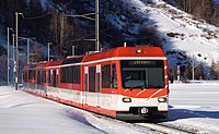
In pure cog railways - mostly mountain railways a few kilometers long - the cogwheel drive is constantly engaged. The running wheels of the locomotives are usually not driven. The vehicles cannot move on routes without a rack, which is why the relatively short flat sections in the terminal stations and the entrances to the workshop are usually equipped with racks.
In the past, the trains of the pure cogwheel railways consisted of a locomotive and one to three cars, depending on the gradient. The locomotive was always arranged downhill so that the cars were pushed uphill and the installation of the two mandatory mechanical brakes was limited to the locomotive. Today, multiple units or multiple units are mostly used.
Railways with mixed adhesion and cogwheel operation were built where there are only individual sections with steep gradients. In such railways, the locomotives are equipped with a combined drive. Occasionally there are separate drives for the impellers and the gear. There were also railways in which adhesion railcars were pushed onto the rack sections of rack-and-pinion locomotives (e.g. the Stansstad-Engelberg-Bahn or the Rittner Bahn ).
The advantage of mixed drives is that where the gear is not in mesh, it can be driven at a higher speed. On rack sections, the speed is limited to 40 km / h according to Swiss regulations, which are usually used as a reference in this area. At least some of the cars must be equipped with brake gears.
Traction vehicles for mixed rack railways are more complicated than pure adhesion vehicles. The Zentralbahn and its predecessors procured traction vehicles without cogwheel drive for the extensive traffic on the valley routes. On the other hand, the wagons of the Rhaetian Railway that can be transferred to the Matterhorn-Gotthard Railway , which does not operate any rack sections, are equipped with brake gears.
See also: Sections motor vehicles for pure cog railways and motor vehicles for mixed railways
Racks on funiculars

Up until the 1890s, racks were used as braking devices for funicular railways .
For the Stanserhorn Railway , which opened in 1893, Franz Josef Bucher and Josef Durrer developed a caliper brake that managed without an expensive rack.
The Nerobergbahn in Wiesbaden , which is still in operation, has a brake rack . Before the renovation in 1996 , the Zürcher Polybahn and the disused Malbergbahn in Bad Ems had a brake rack .
Towing locomotives

Ships are towed through the locks of the Panama Canal with towing locomotives . In order to increase the pulling power of the locomotives, the rack lies continuously in the towing tracks, i.e. also in the horizontal sections.
The considerable lateral pulling forces that occur when pulling the ships are taken up by horizontal guide rollers. These roll on the flanks of the racks, which are similar to the Riggenbach type.
In the parallel tracks for the empty runs back, there are racks only in the short, but up to 500 ‰ steep ramps next to the lock heads.
Gauge
Rack railways can be built in any gauge as long as it allows the rack drives to be installed in the drives. The oldest cog railways in Switzerland are standard- gauge, either because a different gauge was not permitted before 1872 or to enable the transition to neighboring standard-gauge routes. Vehicles with standard and meter gauge trains are less prone to tipping over than those with 800 millimeter gauge , which is particularly important in the case of foehn storms . Standard and broad-gauge railways allow a greater transport capacity, but because of the potentially heavier vehicles they require a more massive construction of the superstructure and substructure as well as larger arc radii. Because these conditions are often not met by mountain railways, the majority of rack and pinion railways are meter-gauge, less often regular gauge. Broad-gauge cogwheel routes are an exception because of the low occurrence of broad-gauge lines. One example is the Raiz da Serra - Paranapiacaba section of the Santos – Jundiaí line in the Brazilian state of São Paulo with a gauge of 1,600 millimeters.
Advantages and disadvantages


Rack railways are used between adhesion railways and cable cars . Rack railways are particularly suitable for opening up traffic to terrain with different topographical characteristics, where alternating flat and steep sections of the route can be driven continuously in adhesion or rack and pinion mode. In addition, they are justified in the case of relatively long steep stretches with large required transport capacities. Its unlimited route length is advantageous, whereby the railway can be built for optional adhesion and rack and pinion operation, depending on the terrain. In addition, inclines and declines can alternate. Operating a tractor is more complex than operating a mixed rack railway. Typical examples of routes integrated into the railway network are the Matterhorn-Gotthard-Bahn and the Zentralbahn , which not only serve tourism, but also regional development for the local population.
costs
The high investment costs are disadvantageous, especially if the routes have to be laid in difficult terrain. The construction of the carriageway and the creation of bridges, tunnels and barriers against falling rocks and avalanches are expensive, so that the construction of a rack railway can be considerably more expensive than that of a cable car . The special designs on vehicles and rails are also cost-intensive. In 1991, what was then the Lucerne-Stans-Engelberg Railway planned to increase its transport capacity. The price of a powerful double multiple unit with 2100 kW for a gradient of 246 ‰ was estimated at 16 million Swiss francs, as much as for a short intercity train with a 2000 locomotive and five Eurocity cars . Replacing the eight existing BDeh 4/4 multiple units alone would have cost around 130 million francs. Instead, it was preferred to build the Engelberg Tunnel, budgeted for 68 million francs, with a 105 ‰ gradient.
Driving speed
Another disadvantage is the relatively low travel speeds, especially for safety reasons when driving downhill with consideration of safe braking during normal operation and in emergencies.
| Vehicle type / slope | ≤ 20 ‰ | 60 ‰ | 90 ‰ | 120 ‰ | 160 ‰ | 250 ‰ | 300 ‰ | 480 ‰ |
|---|---|---|---|---|---|---|---|---|
| Older vehicles (built before 1972) | 35 | 28 | 22.5 | 19th | 16 | 12th | 10.5 | 6th |
| Modern bogie vehicles | 40 | 39 | 32 | 27.5 | 23 | 17.5 | 15th | 9 |
The driving speed can be higher when driving uphill. It is essentially determined by the traction performance of the locomotive.
Suitability for freight transport
The cog railway is suitable for both passenger and freight transport, which is particularly important for lines that serve regional development. The Matterhorn Gotthard Railway (MGB) and the Wengernalp Railway play an important role in developing the car-free areas of Zermatt and Wengen . The MGB also opened up a construction site for the Gotthard Base Tunnel and ran freight trains with building materials every day. There are or were cog railways that are almost exclusively or entirely intended for freight transport, such as B. the railway line between São Paulo and the port city of Santos in Brazil, the discontinued coal transport line Padang – Sawahlunto of the Indonesian State Railways or earlier the Transand Railway between Chile and Argentina or the route to the construction of the Gotthard Base Tunnel near Sedrun .

Two He 4/ 4s from MRS Logística transport goods trains with a trailer load of up to 750 t on a 104 ‰ gradient .
Cement train of the Matterhorn-Gotthard-Bahn (MGB) on the Oberalp route with an HGe 4/4 II

Downhill freight train of the Wengernalp Railway with a He 2/2

HGe 4/4 I in front of a freight train of the then Furka-Oberalp-Bahn around 1980


The mostly very short industrial railways made up a small part of the world's cogwheel routes. Most of the industrial railways in Germany were built primarily for mining and heavy industry .
Environmental aspects


Although rack railways and adhesion railways are environmentally friendly means of transport, certain negative influences can hardly be avoided. The construction of the route leads to structural interventions in nature for all land transport. Thanks to the possibility of steep lines, however, a short route can be chosen and the track fitted into the terrain. To traverse of forests is a trail in the high forest of about ten meters in width necessary (outside of a narrow corridor but is a low strip of forest possible. Niederwald is a valuable habitat that has become rare since the 1950s). Wild animals get used to the railway operations and are not bothered by the trains.
The energy consumption of rack railways is considerably higher than in adhesion mode. A 50-ton train needs around 30 kWh / km to cope with the incline resistance on a 250 ‰ gradient . However, part of this can be recovered using the electric recuperation brake . Electric drives lead to higher construction costs than railways operated with diesel engines. But they are more efficient, locally emission-free and produce less noise.
Like all movable gears, a gear train needs lubrication, typically with grease. This is consumption lubrication, so lubricant remains on the rack. The amount of lubricant required depends heavily on the weather and is highest in a snowstorm. Lubricant can e.g. B. be washed into the ground by precipitation. In order to avoid environmental damage, no ordinary machine grease (mineral oil product) may be used, but only comparatively expensive - and less temperature-resistant - vegetable or animal fats.
technology

3) Theoretical tip circle of the gear (slightly larger with respect to space requirement)
4) Theoretical tip line of the rack (with respect to space requirement somewhat higher)
When differentiating between different technical solutions, one speaks of different rack systems . Only the racks differ significantly, while the gears are all similar.
Rack systems

The four best-known rack systems in the world bear the names of their respective inventors, all of whom were Swiss :
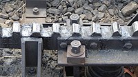
1. Riggenbach system: ladder rack (round bolt between two profile bars ),
2. Strub system: rack (“rack”),
3. Abt system: 2 or 3 parallel racks (“lamellae”),
4. Hole punch system: lying on its side Rack with opposing teeth.
Your solutions have all proven themselves right from the start. They were often varied by other designers, but none of them had to be fundamentally changed over time (the variation usually only affected the splint and the connection between the teeth and it).
Ladder racks
- System - Niklaus Riggenbach


- Riggenbach's rack was patented in France in 1863. The teeth are used as rungs between two U-shaped profiles. Originally they were riveted, today they are welded. This design is characterized by trapezoidal teeth, which enables involute teeth and thus constant power transmission. Investigations showed that the introduced tooth shape was optimal. Their flank angles were also adopted for the later rack designs. The Riggenbach rack is robust because of its massive construction, can be manufactured with simple means and has the second largest distribution of all systems.
- On the railways on the Rigi, which went into operation from 1871 to 1875, the cogwheels protrude below the upper edge of the rails. On the Rorschach-Heiden-Bergbahn (RHB), which opened in 1875, the cogwheel tip circle is located above the top edge of the rail, so that the traction vehicles can enter the Rorschach station using conventional switches .
- Since the rack cannot be bent afterwards (high flexural rigidity of the two profile rods mounted in parallel), the rack sections must be manufactured precisely for the required radius. A rack and pinion line is therefore planned in such a way that it can be created with as few basic elements as possible. On the 9.3 km long rack sections of the Brünigbahn, for example, there are only curves with a radius of 120 meters.
- The installation of Riggenbach racks in points requires special designs. The two U-profiles diverge in the area of the switch device, the rungs are lengthened accordingly. If there is sufficient distance, the rack splits into two strands. High-lying racks are guided over the rails. The rack section that crosses the intermediate rail to be traveled on is turned away to the side. In the case of deep racks, the intermediate rails are moved together with the racks, initially transfer platforms were used, while today the Riggenbach rack within a conventional switch, among other things. is replaced by a bendable rack (see section switches and other track connections ).
- The Riggenbach rack is mounted on steel saddles or attached directly to the sleepers. When using the relatively narrow saddles, the snow is also pushed downwards at these points and not compacted between the U-profiles.
There are also various modified types:
- System Riggenbach-Pauli - Arnold Pauli

- The rack improved by Maschinenfabrik Bern (later Von Roll) enables smaller curve radii. The "teeth" (bolts) are mounted higher (the gear wheel does not dip as deeply into the two profile bars).
- The Riggenbach-Pauli rack was first used in 1893 on the Wengernalp Railway and the Schynige Platte Railway .
- Systems Riggenbach-Klose and Bissinger-Klose - Adolf Klose

- So that the bolts with the tooth profile cannot twist, they rest with their flat underside on a rib that is also inserted horizontally between the two rods.

- This somewhat more complex system was used as the Riggenbach-Klose rack only for the Appenzell tram St. Gallen – Gais – Appenzell and on the Freudenstadt - Baiersbronn route for the Murgtalbahn and as the Bissinger-Klose system for the Höllentalbahn and the Honau-Lichtenstein cogwheel train .
- System Riggenbach : Special construction for level crossings
- During the renovation of a section with a Strub rack (see below), the St. Gallen-Gais-Appenzell-Altstätten-Bahn built a special construction of a Riggenbach rack without raised cheeks for two level crossings (see also the picture on the left in the rack systems section ).
- System Riggenbach : Panama Canal
- In the towing railway on the banks of the Panama Canal , special racks are used to overcome the differences in height at the locks , which are also based on the Riggenbach system.
- System Morgan - Edmund C. Morgan

- Morgan developed a system related to the Riggenbach rack that used the rack as the third rail to power the electric locomotive. The system has been used in mines in the United States and by the Chicago Tunnel Company .
- System Marsh - Sylvester Marsh

- The system consists of a ladder rack with teeth made of a round profile between two bars with an L-profile (U-profile at Riggenbach). It is used on the Mount Washington Cog Railway , which was built from 1866 and completed in 1869, and was also used for the quarry railway in Ostermundigen near Bern. In contrast to Riggenbach, Marsh largely refrained from marketing his system.
- On the Ostermundigen works railway, which opened in 1871, the racks were moved so high that the tip circle of the toothed wheels was so far above the top edge of the rail that the locomotives could use the control switches in Ostermundigen station.
Aligners
- System Strub - Emil Strub


- The Strub broad foot splint with involute teeth is the youngest of the three systems with teeth pointing upwards ( Riggenbach, Strub and Abt ). The first application was the Jungfrau Railway in the Bernese Oberland . The gear trains built since then mainly only used this rack. However, their distribution remained low because hardly any new cogwheel lines were built after that.
- The teeth are milled into a rail similar to the wedge head rail. Strub racks are expensive to manufacture, but easy to lay. They are fastened to the sleepers like running rails according to the superstructure type K (same fastening material for running rails and toothed rails), they can be welded without gaps, and they are undemanding in terms of maintenance.
- On the meter gauge network of the Appenzeller Bahnen , racks from the Strub system were used with the same gears as the Riggenbach ladder racks because the pitch in both racks was identical.
- Hooks that grip around the rail head are intended to prevent climbing on particularly steep sections . H. the locomotive or a railcar cannot be lifted off the track by the forces acting on the teeth. The experience with these safety tongs was not clear. The Jungfrau Railway was the only rack railway on which the rack was originally also part of a sliding caliper brake. Because of the small contact area on the rail, the wear was too great, so this application was abandoned. The caliper brake was only used as a holding brake for freight wagons .
Lamellar racks
- System Abt - Carl Roman Abt


- As a further development of the Riggenbach system, two or three toothed racks ("lamellae") with teeth pointing upwards were installed next to one another. The relatively narrow rods can be bent enough to adapt to any arc radius. By duplicating the bars, the contact area between the gear wheel and the racks remained sufficiently large. The width of the lamellae depends on the greatest tooth pressure that occurs; the majority of them are 32–40 mm apart. Abbot was the only one to use a tooth pitch of 120 mm instead of the usual 100 mm.
- The Abt solution should also avoid the problems with pitch errors on the rack joints that arose with the Rigibahn , but it should also be cheaper than the Riggenbach rack.
- This multi-lamella design achieved the greatest spread worldwide. The use of the three-lamellar rack was limited in Europe to the Harz Railway and the Caransebeş – Bouțari – Subcetate railway in Romania. Overseas, the three-lamellar Abt system is used on the Santos – Jundiaí and Ikawa line and, earlier, on the Bolan Railway , the Transanden Railway and the railway over the Usui Pass .
- The slats rest on cast iron saddles that are bolted to the sleepers. They are shifted against each other by half or a third of their length so that the joints are not at the same height. A particular advantage when using several slats is the smooth, jolt-free and operationally reliable power transmission due to the division of the slats offset by half or third of a tooth; In this case, however, a torsional suspension of the drive gear disks against each other is necessary in order to achieve an approximately even distribution of the tooth pressure on the lamellae. The rack entrances with sprung tips and smaller teeth were part of the system from the start. There is no device for this rack to secure vehicles against climbing. Sometimes only one lamella is installed in switch areas or in flat sections. It is advantageous that in rack turnouts with the Abt system, no movable intermediate rails are generally required. The slats are swiveled out of the passage area of the wheels on both sides in the intersection area.

- The system was developed in particular for continuous operation on routes with rack and pinion sections, the gears are generally above the upper edge of the rail. The first application was the Harz Railway from Blankenburg to Tanne, built between 1880 and 1886, on the Halberstadt-Blankenburg Railway .
- System Von Roll - Von Roll Company

- The rack developed by Von Roll (today Tensol) is a lamellar rack only in name, namely a single-lamellar rack. It has the same tooth pitch as the Riggenbach and Strub racks. It differs from the latter in its basic shape: a simple wide-flat profile instead of a wedge-head rail similar to a profile. This rack is primarily used in new buildings and as an inexpensive replacement of old racks according to the Riggenbach or Strub systems. It is thicker (30–80 mm, depending on the tooth pressure) than one of the Abt lamellas, but its flexibility is sufficient to be more flexible than the originals according to Riggenbach or Strub. It can also be welded continuously. Special profiled steel saddles are used for fastening to the sleepers.
Racks for horizontal meshing of two gears
- System Locher - Eduard Locher


- Two opposing gears mesh with the herringbone-like rack from the sides. The tooth pitch is 85.7 mm. The fact that the gears are pushed out of the rack (“climbing”) is compensated for by the opposing arrangement of the two tooth pairs.
- A flange on each of the gears is used to guide the vehicles horizontally (the flange acts radially against the substructure of the rack) and is an additional measure against separation of the gearing in the width direction (the railcar rises up; the flange acts axially from below against a narrow additional rail on the substructure) .

- The Locher system is the only one of the rack and pinion systems used that enables a gradient of significantly more than 300 ‰ to be overcome because it prevents climbing out of the rack. So far it has only been used on the Pilatusbahn . The Locher rack has not found any further use because of the high costs (only a similar system at the ship lift on the Krasnoyarsk Reservoir ).
- Track connections require transfer platforms or track turner, since switches cannot be implemented. It was not intended for mixed operation routes (both rack and pinion and adhesion drive).
- System Peter - HH Peter

- Like Strub's herringbone rack, the Peter herringbone rack consists of a rail-like carrier with horizontal teeth milled into the head on both sides. The rack is easier to manufacture than Locher's. It was intended for the Karlsbad-Dreikreuzberg-Bahn with a 500 ‰ gradient, the construction of which was discontinued due to the outbreak of the First World War .
Other types
- Wetli system - Kaspar Wetli
- The roller wheel system was supposed to be used on the Wädenswil-Einsiedeln railway , but did not come into commercial operation due to an accident during a test drive on November 30, 1876 .
- System Fell - John Barraclough Fell
- The Fell system is not actually a cogwheel train, but a middle rail friction wheel drive on a third rail located in the middle of the track.
Arrangement of the rack system


Position of the racks in the track
The rack is always arranged in the center of the track and attached to the sleepers using angle pieces , rack saddles or ribbed plates and conventional rail fasteners . It is either lower than the tracks or its teeth protrude above the upper edge of the track or rail (SOK).
Low-lying racks are favorable for level crossings , as there are no differences in height in the road surface and the resulting gaps are no wider than with rail grooves. The construction of points is time-consuming, because low-lying toothed racks require movable intermediate rails for the passage of the toothed wheels protruding below the top edge of the rails. Because of these cogwheels, corresponding vehicles cannot cross other tracks and cannot use control switches.
High-lying racks interfere with the passage of road vehicles (bump). A complex solution is to temporarily lower the rack in the overpass area. The racks on the Martigny – Châtelard (Switzerland) line are in a particularly high position , because the subsequent adhesion-driven line to Saint-Gervais (France) has a particularly high brake rail from the Fell system installed in the middle of the track . The pitch circle of the rack is 123 mm above the upper edge of the rail (SOK) so that the carriage can pass through the entire route. One advantage of the high-lying racks is the less complex switch construction: The intermediate rails are continuous because the racks can be swiveled in over them.
Rack joints can be welded seamlessly on modern, heavy superstructures such as running rails. The individual lamellas of Abt racks do not have the same length in arches. To compensate for the length, comparatively short lamellas with butt joints of different widths in the two lamella trains (and the associated pitch errors) have been used so far. Today one of the two rack lamellas is made in arches with a different pitch.

roller bearing rollers (blue),
eccentric. Hollow shaft (green),
eccentric disks (red),
wheelset shaft (dark red)

Round tooth tips make it easier to move into the rack and prevent pitch errors from climbing up, as experience with the Rigibahn showed very early on.
Engagement of the gears in the rack
The tolerance for the height of the rack is +2 mm, that for the height difference at the rack joints is ± 1 mm. The highest position of the drive and brake gears results from new running wheels . In their lowest position (greatest wear of the impeller), there must be no jamming in the rack and no contact between the tooth tip and the tooth base.
Impellers wear out during operation, making them smaller in diameter. With mixed operation (adhesion and gear drive) the wear is high because of the relatively high mileage. Drive and brake gears, on the other hand, wear on their tooth flanks , but the pitch circle diameter that is decisive for the meshing does not change. With adhesion and gear drive on the same wheelset shaft , the distance covered by the wheel set in one revolution is reduced, while the distance covered by the drive gear remains the same. Because the drive and brake gears of bogie traction vehicles or newer frame locomotives are firmly pressed onto the drive axle and the wheels are loosely mounted on the axle or on a hollow shaft , only slight tire wear is permitted (see also sections Electric and diesel-electric traction vehicles and Electric and diesel- powered ones Traction vehicles ).
With the ABeh 150 and ABeh 160/161 of the Zentralbahn , which are equipped with separate drives, the restriction of low tire wear has become obsolete. In the articulated railcars delivered in 2012 and 2016, a newly developed gear drive with eccentric height adjustment is used, which in terms of design corresponds to a conventional gear drive with claw bearings , as is known from pure cog railways. The drive or brake gears are not supported directly on the wheelset shaft , but on an additionally inserted, non-rotating hollow shaft that is supported on the wheelset shaft via eccentric disks. By turning the eccentric disks, the meshing of the teeth can be easily adapted to the wear of the wheel.

In steam locomotives with the Winterthur drive system , the adhesion drive and the gear drive are mounted in the same frame. This allows the depth of tooth engagement to be readjusted by tightening the suspension springs as the tire thickness decreases .
Standard railroad cars, which are to be regularly carried on cogwheel routes, usually require a brake gear, which is built into one of the bogies , because of their greater mass . The height of the brake gear is readjusted according to the wheel wear.
Carriages of mixed adhesion and cog railways can be equipped with an adhesion brake and a delayed-action gear brake , a so-called secondary brake . Both bogies on the 246 ‰ steep rack and pinion route to Engelberg were equipped with a brake gear after the brakes of the very light passenger cars with only one brake gear, which were purchased in 1964, had not proven themselves. Wagons, which should also be usable on the Giswil – Meiringen section of the Brünig Railway and on the lines of the Berner Oberland Railway with inclines of up to 120 ‰, were equipped with a changeover device to avoid overbraking on these sections.
Rack entry

When entering the rack, the drive and brake gears must be synchronized with the rack and made conphas. The speed of the gears must be adapted to the driving speed (synchronization: peripheral speed of the gear pitch circles equal to driving speed), and the gear teeth must meet tooth gaps in the bar (be in phase with them). There is no need to adjust the speed if the gear drive is coupled to the impeller drive. In these cases, when the two rows of teeth are conphased, the running wheels must slip slightly on the rails.
The entry from an adhesion section onto the rack takes place at reduced speed (generally ≤ 10 km / h). The speed does not have to be reduced when exiting the rack into an adhesion section.
There are essentially two entry systems that can be used equally with all rack and pinion systems. The second (newer) system is an improvement on the first (older) system.
System dept
Until a few years ago, the rack entrances were built according to Roman Abbot's old plans .
They consist of a piece of rack mounted in front of the fixed rack and spring-mounted at its tip (previously at both ends). The height of the teeth increases continuously from almost zero at the beginning to the normal height at the end. The tooth pitch also grows continuously from oversize at the beginning to standard dimensions at the end. This tooth geometry is primarily used to create conphas. Initially, only one wheel tooth engages between the shortened bar teeth, so that it can take up the central position in the bar tooth gap that is getting smaller and higher without being prevented by another wheel tooth. Because of the initially larger tooth pitch, the probability of hitting a tooth gap is greater. Should not slip into a gap an apt on a shortened and sharpened rod tooth sprocket and a upgrade coming two relatively high and long prevent the handlebars first derailment. However, by the end of the control arm, the gearing must have engaged again.
- Rack entrances: System dept

Rack entrance on Riggenbach rack, spring-mounted rack piece, no control arms, Heiden train station of the Appenzeller Bahnen

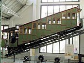
Rack entrance on Abt rack (two slats), no control arms, Bosnian-Herzegovinian State
Railways, Ljubljana Railway Museum
Excerpt from the left picture (in front of the second pole-lafer place): Teeth wear from the brake gears, which hit when entering the car in order to be accelerated to the run-in speed

Rack entry on Von-Roll rack (on the route: Strub-), wheel guide, Altstätten – Gais railway line of the Appenzeller Bahnen
Unevenly worn teeth of the rack entrance at the Stoss stop of the Appenzeller Bahnen
(different entrance than in the picture on the left)


System Marfurt

1) adhesion section
2) rack portion
3) accelerator
4) Synchronisierlamelle
5) sprung Einfahrlamelle
6) suspension rack
7) Radlenker
The modern rack and pinion entrance to Marfurt (referred to as the Marfurt system or the Brünig system) works better than the previous one according to the department. It consists of 3 parts, each for a partial task:
- Acceleration element: a rubber-covered bar on which the stationary brake gears of the non-driven carriages are set in rotation by frictional contact,
- Synchronizing lamella: a rack like the Abt system , on which the gears are synchronized with the rack,
- Retractable lamella: a rack that moves slightly in the opposite direction of travel when the cogwheels open.
The main innovation is the retractable lamella. Their small backward movement causes one tooth each of the lamella and the toothed wheel to be moved against each other, whereby their correct (conphase) mutual position is established. The lamella stands on two inclined levers. In the basic position, its front end is raised, the rear end is lowered, and at the rear it hits the fixed rack with a reduced tooth pitch. The approaching gear pushes the front end down and in the opposite direction of travel (forwards). The rear end is lifted to the correct height. The forward movement also ensures that the correct tooth pitch is restored at the back. The basic position is taken by the force of a spring. The rocking back and forth of the retractable lamella is hydraulically dampened (avoidance of vibrations).
The Marfurt system allows gentler entry at a higher speed (up to 30 km / h) and, thanks to the almost complete avoidance of entry noises, a significant noise reduction. There is less wear and tear, the wear parts are defined and easy to change.
- Rack entry: System Marfurt at the Appenzeller Bahnen (AB) in the freight yard, St. Gallen

Rack entrance, from front to back: Accelerator element, synchronizing lamella, drive-in lamella, Strub rack

above: synchronizing
lamella below: retractable lamella with hydraulic damping (left, double)
entry from the right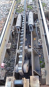
Einfahrlamelle from the point of view of the engine-vehicle guide
blade mounted on two levers,
two motion damper


Signaling

Rack sections are signaled along the route in Switzerland as follows:
| description | importance | Relationship to other signals | Image German-speaking Switzerland |
Image French-speaking Switzerland |
|---|---|---|---|---|
| Advance signal for rack section | The signaled maximum speed applies from the start signal. | The distant signal is about 150 m before the start signal. |
 |
|
| Start signal for rack section (tronçon à crémaillère) | This signal is the entrance to the rack. When entering the rack, the indicated maximum speed applies until the last car passes. | An early signal can precede it and an end signal follows. |  |
 |
| End signal (final signal) for rack section | This signal is the end of the rack. | An initial signal precedes it. |  |
 |
Switches and other track connections
Transfer platforms, turntables and track turner
At the time of the first rack railways, the switch had long been state of the art in railways. Switches for rack railways, in which the racks cross with the inner rails, first had to be developed, which is why transfer platforms were primarily used as track connections, as was the case with the oldest rack railway on Mount Washington and the Arth-Rigi Railway .
Transfer platforms or turntables are still to be found in the station and depot areas of the rack railways.
Transfer platform with curved track sections instead of a switch on the oldest cogwheel mountain railway, the Mount Washington Cog Railway .

Transfer platform of the Pilatusbahn in the Ämsigen crossing station; the Locher system does not allow switches.
Turntable in the valley station of the Vitznau-Rigi-Bahn

Instead of transfer platforms, the Pilatusbahn also uses track reversers as shown here.


Tongue softening

.jpg)
.JPG)

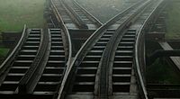
Racks soft equipped with movable rack members, so that the racks of one strand can cross the tracks of the other strand. Because this ensures uninterrupted gear meshing, they can also be installed on inclined stretches. In the case of railways with a mixed drive, the switches are often located on the adhesion sections, because rack switches are more complex and expensive than conventional switches. On the other hand, at junction stations with continuous racks like in Tschamut-Selva on the Oberalp route, the speed does not have to be reduced because no rack entry is necessary.
The advantage of tongue switches with rack compared to classic drag switches with sliding track grid is the only slight temperature- related changes in length of the short movable rack parts. Noteworthy pitch errors cannot occur due to temperature changes. Rack turnouts are built with comparatively small branch track radii due to the low speeds, multiple locks in the tongue area or movable frog tips are therefore not required.
In 1875 Riggenbach installed the first rack and pinion turnout on the Rorschach-Heiden mountain railway in Wienacht to enable access to the sandstone quarry there. Instead of the Riggenbach ladder rack, there is a single-lamellar rack inside the switch. This point switch corresponds to the type used for unilamellar rack routes today, which is used mostly even at tracks with Riggenbach rack.

On the turnouts of the Wengernalp Railway and Schynige-Platte Railway, which opened in 1893, with a track width of 800 mm and Riggenbach rack, the rack was interrupted over a length of 90 cm. The locomotives needed two drive gears to ensure uninterrupted operation. Today the two railways use points with movable slats.
The Monte Generoso railway has been using rack turnouts of the Abt system since 1890. Their construction is simpler thanks to the two-lamellar rack, because only one of the two rack lamellae is used in sections within the turnout (see picture in the lamellar racks section ). Such a switch can only be used on small slopes, where the full tensile force does not act on the rack. The tangential springs of the drive gears, which are softer in newer traction vehicles, lead to heavy wear after single-lamellar sections when re-engaging the second lamella, since the loaded ring gear is twisted in relation to the unloaded one. Traditional rack turnouts from the Abt system should therefore no longer be used. If the Abt rack turnouts are to be driven on with the full drive or braking force, then you get movable intermediate rails for the implementation of the full rack cross-section and additionally movable racks in the tongue area according to the drag switch principle. Examples are the switches at the Gornergratbahn and in the Schöllenenschlucht
The Berner Oberland Railways equipped their new rack and pinion turnouts with three individual drives in order to avoid the linkage, which is prone to failure in winter.
Rack switches with deep racks or with interrupted intermediate rails as well as any form of drag switches cannot be driven on. Because a collision always leads to derailment with serious consequences, especially on steep inclines, collisions must be avoided at all costs. In the case of the Abt system and high-lying Riggenbach racks with uninterrupted intermediate rails, slide-on switches have been implemented, which switch to the required position in a purely mechanical way when the frog is driven on (see picture above ). They were installed, for example, on the Rochers-de-Naye and Schynige-Platte lifts .
Spring switches


Since 1999 the Rigi-Bahnen and since 2004 the Dolderbahn have been using newly developed spring switches in which the track is bent from one end position to the other along a defined curve. To compensate for the temperature-related changes in length over the entire length of the switch, the spring switch is designed in such a way that the elongation of the rack and the frame underneath act in opposite directions. The two length expansions thus cancel each other out, the tooth spacing at the joint remains within the tolerance and tooth pitch errors are avoided.
The simple construction of the spring switch has - in contrast to the usual rack switch, which is structurally derived from the adhesion switch - fewer moving parts with correspondingly less wear and tear and does not require switch heating . The application would also be possible with adhesive sheets, e.g. B. as a double or crossing switch .
Helical twist in the switch
On track sections with gradients of more than 40 ‰, the helical twist must be taken into account in track curves (see section Track twist in inclined track curves ). Turnouts represent a special case in this regard. They must be in one plane so that they close properly and the tongues do not jam. In the case of a switch on a slope, the twisting of the branching line is therefore prevented by design. Only after the last continuous sleeper can the track twist again.
If a switch is located on the slope with the switch start on the valley side, the geometry alone results in an elevation of the rail on the outside of the curve of the branching line. The tendency of the elevation corresponds to that which would have been built into a curve without a switch for reasons of driving dynamics. If the curve ends after the switch, the track can be twisted.
If, on the other hand, there is a turnout opposite to the turnout catch on the mountain side, the cant is on the inside of the curve for the same geometric reasons. However, this is unfavorable in terms of driving dynamics, because the now negative camber increases the centrifugal forces acting on the vehicle . Such a switch may only be driven on at reduced speed in the branching line. The effect can be reduced with a larger turnout radius and thus a lower turnout inclination as well as with an outer curved turnout . In the case of the outer curved turnout, the fault can be distributed over the two tracks. With this switch configuration, too, the track is twisted after the last continuous sleeper.
In the case of the transfer platforms and track turner used on the Pilatusbahn ( Locher system ), the twisting of the helix is meaningless, because the twisting of the two tracks is independent of each other. With other rack and pinion systems, such track connections are not an alternative for reasons of cost.
Traction vehicles
.jpg)
Electric and diesel powered locomotives and steam locomotives are still used on rack railways . Of the rack-and-pinion locomotives that operate around the world, only around 15% run on diesel oil and 5% on steam.
The following three power systems are in use on the existing electric rack and pinion railways:
- Direct current with different voltages for short and medium operating lengths. The majority of the DC railways use a voltage of 1500 volts. It allows distances of four to five kilometers between the rectifier stations .
- Single-phase alternating current for some pure cog railways and for longer mixed adhesion / cog railways (see list of cog railways ). The high voltage of the alternating current allows large distances between the substations , but the locomotives require a transformer , the high weight of which is disadvantageous.
- Three-phase current for the pure rack railways on the Jungfrau , Gornergrat , la Rhune and Corcovado . Classic three-phase AC technology requires double overhead lines , but allows simple recuperation brakes , which, however, do not allow higher speeds on the uphill than downhill.
The construction and operation of rack-and-pinion vehicles are and were technically very demanding. Compared to adhesive membranes, there are limits due to:
- tight curves, large climatic differences and rough winter operation,
- Load limits of the rack and the pulling devices ,
- The train cannot derail on the descent, even in tight bends with a maximum gradient.
The most important manufacturer of rack-and-pinion locomotives since 1874 was the Swiss Locomotive and Machine Factory (SLM) in Winterthur. After the dissolution of the SLM in 1998, the rack railway division was taken over by Stadler Rail . More than two thirds of the locomotives in operation on existing rack railways worldwide come from SLM or Stadler. The Floridsdorf locomotive factory in Vienna owned the sole patents for the Abt rack and pinion system for Austria-Hungary . Along with the globally active SLM, it became the largest producer of rack rail vehicles and supplied almost all rack locomotives ordered in the dual monarchy, including the machines for the Erzbergbahn and Bosnian-Herzegovinian state railways . In Germany, the Esslingen machine factory acquired a special reputation for building cogwheel locomotives. In the USA, Baldwin Locomotive Works in Philadelphia supplied some American customers.
The design names of Swiss locomotives and railcars differentiate between pure and mixed rack railways. In the case of pure cogwheel vehicles, the h comes first after the capital letters (e.g. Bhe 4/4), in the case of a combined adhesion and gear drive at the end (Beh 4/4). H 2/2 is a gear steam locomotive of the pure, HG 2/2 of the mixed system.
Traction vehicles for pure rack railways
In the pure system of rack and pinion railways, the wheels are only used to support and guide the vehicles. The locomotion of the vehicles takes place exclusively via the gears. Such rack railways overcome maximum gradients of 250–300 ‰ with vertically meshing gears.
Steam locomotives
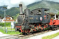
The steam locomotives of the pure cogwheel railways have one or two drive gears and, if there is only one drive gear, usually a brake gear. For larger pulling weights, two drive gears must be used so that the tooth pressure does not become too high and to counter the risk of the gear wheel climbing out of the rack. Such locomotives were z. B. from the Wengernalp , Snowdon , Schafberg and Schneebergbahn . A locomotive with three pinions was used at Pike's Peak Railway .
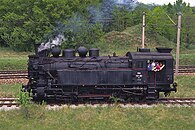
Cogwheel steam locomotives are basically built as tender machines in order to keep the train mass as low as possible and to use the mass of the locomotive to secure the meshing of the teeth. More time is allowed for on the way to replenish the feed water supply.
As there was a fear of fluctuations in the water level in the boiler on the different slopes, the first locomotives on the Vitznau-Rigi Railway were equipped with a standing boiler. In operation and especially in maintenance, these boilers did not prove themselves , so that after 12 to 19 years they were replaced by horizontal boilers inclined by about 10%.
The dominant market position of SLM led to a certain standardization of the types. The series of pictures each illustrate the development of the rack-and-pinion vehicles, whereby the manufacturer is mentioned for vehicles not from SLM or Stalder Rail:
H 1/2 of the Arth-Rigi-Bahn with a drive gear and horizontal boiler, supplied by the International Society for Mountain Railways (1875)
The steam railcars Bhm 1/2 of the Pilatusbahn are a special construction for the rack and pinion system Locher (1886)

The Abbot -sche gear locomotive H 2/3 of the Monte Generoso Railway with two drive gear wheels was an original design of the SLM (1889)

Machines with two drive gears are driven by a single-armed rocker arm R with a low pivot point a


Electric and diesel-electric traction vehicles


1) traction motor
2) pre-gear
3) cardan shaft
4) gear brake
5) two-stage gear
6) gear brake
7) drive gear
Since there is enough water available in the mountains to generate electricity, the Chemin de fer du Salève in the Haute-Savoie was opened in 1892, the world's first electric rack-and-pinion railway, which was operated with 600 volts direct current. The Gornergrat and Jungfrau Railways were opened before the turn of the century, and the decision was made to use three-phase current in accordance with the state of the art at the time . The vast majority of electrically operated rack and pinion railways have been running on direct current since the 20th century .
Today's vehicles are powered by compact units that include the engine, gearbox , brake drum and drive gear . Each traction motor drives a drive gear that is freely rotating on a wheel set. Because of the relatively low driving speed, the transmission usually has a double ratio. To avoid unwanted wheel relief from the engine torque, the traction motors are usually installed transversely in the bogie . The drive gears with involute teeth always grip the rack with at least two teeth. They are tangentially sprung to compensate for jolts that can be caused by rack pitch errors.
The number of drive axles is determined by the required pulling force. For modern double railcars with four identical bogies, a single-engine design is sufficient in many cases. Bogies with one drive and one running axle each have the advantage of even rack loading, allow double traction of two double railcars and, in the event of derailment, are safer than two motor and two trailer bogies.
He 2/2 of the Gornergratbahn , here as a memorial in Stalden , with two motors and two drive gears (1898)

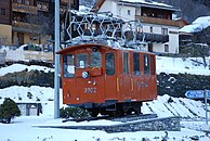
The BCeh 2/3 of the Arth-Rigi-Bahn for 1500 V DC voltage is the oldest rack - and-pinion railcar still in operation in the world (1911)
Bhe 2/4 of Vitznau-Rigi railway , car box in self-supporting steel construction, running and valley side mountain-side motor bogie with two motors and nose-suspended drive (1937)
BChe 2/4 of the Rochers-de-Naye Railway with one drive and one running axle per bogie (1938)

The four-engine ABDhe 4/4 of the Wengernalp Railway with control cars replaced locomotive-hauled trains (1947)

Diesel-electric rack-and-pinion railcar type Bhm 2/4 of the Pike's Peak Railway with two underfloor diesel engines (1960)
The Bhe 4/8 double multiple unit of the Gornergratbahn has four bogies, each with one drive and one running axle. (1965)

The gate control of the BDhe 4/8 of the Jungfrau Railway enables faster uphill than downhill travel even with three-phase vehicles . (1992)

The Hey 2/2 Wengernalpbahn is the first gear vehicle with three-To-rich-ter-to-drive . (1995)

Bhe 4/6 3083 of the three-phase Gornergratbahn with three-phase to three-phase converter (2006)
Four-axle converter mountain locomotive 19 of the Bavarian Zugspitzbahn for 40 t set load to 250 ‰ (2016)


.jpg)
_109.JPG)

.jpg)

The more recent technical developments are used for both pure and mixed rack railways:

Railcar No. 6 of the Bavarian Zugspitzbahn with beads in the side walls to save weight (1978)
Two three-part BDSeh 4/8 of the Matterhorn-Gotthard-Bahn with panorama and low-floor cars and three-phase converter drive (2002)

The gear GTW the Vall de Nuria is based on a large series of Adhäsionsfahrzeugen , which saves costs. (2003)

With biodiesel -powered locomotive M4 "Agiocochook" the Mount Washington Cog Railway , a self-made of the railway company (2008)


Motor vehicles for mixed railways
Steam locomotives
The first locomotive for mixed adhesion and cogwheel drive was the "Gnom" for the 1350 meter long works track of the Ostermundigen sandstone quarry near Bern. The gear wheel ran idle on the adhesion path without any interference.
On the Žakarovce ore railway and then on the Brünig railway and the Padang railway on Sumatra, locomotives with a cylinder pair and coupled adhesion and gear drive were initially used. The simply built machines were suitable for smaller tractive forces, but did not prove themselves in operation on longer routes such as the Brünig line.
The steam locomotives built later have a separate drive, whereby the drive gears on the adhesion sections are switched off. (see section Separate gear and adhesion drives )

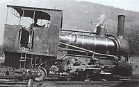
"Gnome" of the Ostermundigen quarry (1871, International Society for Mountain Railways )

Locomotive of the Žakarovce ore railway in today's Slovakia for mixed adhesion and gear operation (1884, Esslingen machine works )

HG 2/2 for the Brünig line of the Jura-Bern-Lucerne Railway for mixed operation (1887)
Achenseebahn locomotive from 1889 with combined adhesion and gear drive (according to the Riggenbach system ), built by the Floridsdorf locomotive factory .
Three-coupler machine kkStB 69 of the Erzbergbahn with rear running axle and two drive gears (1890, locomotive factory Floridsdorf )
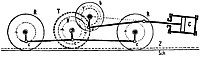
Coupled drives with cylinders C, jackshaft b, ratio v / V, drive gear T, coupling rod c and drive axles R.

"Cortaillod" tram locomotive of the Neuchâtel tram (1892, Krauss Munich )

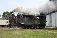
The BHStB IIIc5 supporting tender locomotive (later JŽ 97) for mixed operation on 760 mm gauge ( Bosnian gauge ) with two outer and two inner cylinders (Abt gear system), built from 1894 to 1919 by the Floridsdorf locomotive factory and 38 of them the most popular cogwheel locomotive World.


Electric and diesel powered traction vehicles


In this drive, the gear part is expanded with an adhesion part. The outside diameter of the drive gear is usually smaller than the drive wheel diameter. Therefore two different translations are required. Although they are chosen so that both drive parts should produce the same driving speed, this is only possible with half-worn tires . Before and after, there is a slip between the wheel and the rail with a correspondingly high level of wear. A permanently coupled drive is therefore only suitable for routes with a modest proportion of rack sections. In addition, the permissible wheel tire wear must be reduced to 2%. With an adhesion clutch, the adhesion drive can be decoupled in gear operation, which is common with modern locomotives. The drive gear set is decoupled on the cogwheel section and then runs freely, which eliminates slip. With coupled drives, the tensile force is transmitted to the rack sections both via the drive gear and with static friction via the drive wheels .
In the case of a combination of fast adhesion routes and steep gearwheel routes, it may be necessary to implement the drive with a gearbox in order to have the appropriate drive motor speeds available for both ranges.

Three-phase HGe 2/2 of the Jungfrau Railway with different ratios for adhesion and gear drive (1906)

Railcars BCFeh 4/4 of Martigny-Châtelard train for 750 V DC with Tatzlager drive instead of high-mounted motors (1906)

HGe 4/4 of the Brig-Visp-Zermatt-Bahn (BVZ) for 11 kV 16⅔ Hz alternating current with four drive motors and pawl bearing drive (1929)

ABDeh 4/4 of the St. Gallen-Gais-Appenzell-Altstätten Railway with two traction motors installed under the floor of the car (1930)

Rail buses of the series M1c of the Mediterranea-Calabro-Lucane with gear drive from various Italian manufacturers simplified the railroad operation. (1933)

ABDeh 4/4 303 of the Bernese Oberland Railway with a self-supporting car body and two transversely installed traction motors per bogie (1949)
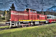
Diesel-hydraulic T 426.0 of the Czechoslovak State Railways for the Tanvald – Kořenov and Podbrezová – Tisovec lines , manufactured by SGP in Vienna- Floridsdorf (1961)

BDeh 4/4 of the Luzern-Stans-Engelberg-Bahn with two gear ratios for the 246 - ‰ - rack and 75 km / h top speed on the adhesion section (1964)

The double railcar ABDeh 8/8 of the BVZ has the performance of a locomotive thanks to the saving of two passenger cars. (1965)

Diesel- electric rack-and-pinion locomotive BB 204 of the Padangbahn of the Indonesian State Railways with four drive axles and four drive gears for a load of 200 tons at 70 ‰ (1982)

.jpg)


Separate gear and adhesion drives
From 1887, it was decided to use the rack on relatively short sections with not more than 125 ‰ incline for overcoming steep valley steps of narrow-gauge adhesion tracks. From the turn of the century to the First World War, the regional railways in Germany implemented more and more steep routes as cogwheel railways, which led to the construction of large cogwheel locomotives.

In the case of steam locomotives, the adhesion drive is generally used on the entire route. The gear drive is used on the rack and pinion sections on the ascent and descent and is shut down again after leaving the steep ramp. As a result, the adhesion and gear drive were separated.
In narrow-gauge locomotives for adhesion and rack and pinion lines, it was not always easy to accommodate the engines. The SLM found a good solution with the Winterthur system , which allows an outer layer and a separate design for the adhesion and gear drive. This enables good accessibility and thus easier maintenance of the engine. With increasing tire wear, the depth of the tooth engagement can easily be readjusted.
The two high-pressure cylinders below drive the adhesion drive axles. In adhesion mode, the lower cylinders work alone with simple steam expansion. The steam then escapes directly into the blowpipe . On the rack sections, the locomotive works in a composite effect , in that the steam is directed after the lower adhesion high pressure cylinder into the upper gear low pressure cylinder. The diameter and piston stroke of the four cylinders are the same. Due to the translation of the back gear , the gear drive works around twice as fast as the adhesion drive, which creates the correct volume ratio between the high and low pressure cylinders. Due to the composite effect, the steam is better used and the result is a lower consumption of coal. There is a good balance between the gear drive and the adhesion drive, which reduces the spin of the adhesion drive. The rapid but not too strong steam hammer of the gear drive causes good steam development. Entering and exiting a rack section is very easy because only the switch valve between high and low pressure cylinder has to be operated. When starting on a rack section, the boiler pressure can be directed directly to the low-pressure cylinder.
The Winterthur system secured a large number of orders for SLM at home and abroad. It was used in many steam locomotives with mixed adhesion and gear drive and was also used by the Esslingen machine factory .

The HG 2/3 of the Appenzeller Tram (ASt) designed by Adolf Klose was the world's first four-cylinder composite rack-and-pinion locomotive . (1889)

The 38 IIIc5 of the Bosnian-Herzegovinian State Railways were the most frequently built cogwheel locomotives in the world. ( Floridsdorf , 1894)

The Winterthur drive system was used for the first time on the HG 2/4 of the winding ASt. (1904)

The 22 HG 3/3 with the Winterthur system drive proved their worth on the Brünig line and on the Bernese Oberland Railway . (1905)

Kitson-Meyer -Gelenklok the trans-Andean web of Kitson & Co in Leeds with the outer frame, Hall's cranks , four driving axles, two drive gears and wheel arrangement D '(3zz) (1909)
Six-axis KkStB 269 of the Erzbergbahn with internal low-pressure cylinders for the two drive gears, manufactured in Floridsdorf (1912)

D1 'locomotive of the Padang Railway on Sumatra, powered by the Winterthur system and a drive gear (1913)

Class X system Winterthur locomotive of the Nilgiri Mountain Railway in India with four coupled axles and two pinions (1913)

Five-axle DR series 97.5 for the Honau-Lichtenstein cog railway from Esslingen , Winterthur system drive with one drive gear (1922)

Series 97.4 of the Erzbergbahn, the world's most powerful cogwheel steam locomotive with internal cylinders for two drive cogwheels from Floridsdorf (1942)


When the Bernese Oberland Railway was electrified in 1914, the tried and tested concept of the existing HG 3/3 steam locomotives with separate adhesion and gear drives was adopted. In this way, the adhesion drive supports the gear drive and relieves the rack. This is particularly advantageous for cog railways with moderate gradients of 80–120 ‰, where a large part of the traction forces can be transmitted without a rack. Separate drives, as they had been successfully implemented up until the 1940s, remained of no interest for a long time because some of the previously expensive drive motors could not be used on the relatively long adhesion routes. In the meantime, the technical environment has changed. The expensive and maintenance-intensive gears can be replaced by lightweight and inexpensive separate asynchronous traction motors .
With a separate drive, the correct speed of the drive gear is not guaranteed before entering the rack. A synchronization device is therefore indispensable in the traction vehicle.

CFeh 3/3 of the Altstätten-Gais-Bahn with two motors only for adhesion sections and one motor only for rack and pinion sections (1911)

In the HGe 3/3 of the Bernese Oberland Railway, one motor acts on the three axles coupled with rods and a second acts on the drive gear. (1914)

85-tonne double locomotive E-100 of the Chilean Transand Railway with four motors for adhesion drive and two for gear drive (1927)

Deh 4/6 of the SBB for the Brünigbahn (Bo'2zz'Bo ') with four adhesion bearing motors in the end bogies and an additional two in the middle gear drive frame (1941)

The diesel locomotives of the ČSD series T 426.0 were procured in 1961 for operation on the Tanvald – Kořenov and Podbrezová – Tisovec routes in Czechoslovakia. The diesel-hydraulic locomotives have two independent fluid transmissions that can be switched on together in gear operation.

Three-part ABeh 160 "Fink" of the Zentralbahn with two adhesion bogies and two gear drive bogies. The gear bogies each have a drive and a running axis. (2012)

The world's most powerful He 4/4 rack-and-pinion locomotive from MRS Logística has two bogies, each with two motors for adhesion and gear drive. (2012)


_Ko%C5%99enov.jpg)


Differential drive

drive 1) motor-side drive shaft
2) sun gear (→ adhesion)
3) ring gear (→ gear)
4) to gear drive
5) to adhesion drive

The differential drive for high-performance gear / adhesion locomotives automatically distributes the pulling force to the adhesion and gear wheels and thus relieves the rack. This drive is suitable for rack railways with a gradient of up to 125 ‰. The traction motor torque is in a as a planetary gear formed Verteildifferential divided between the adhesive and the gear drive. If the adhesion wheels start to spin in poor conditions , the slip limitation integrated in the drive takes corrective action and the tractive force that can no longer be transferred to the rails is continuously taken over by the drive gears.
In braking mode, the device works accordingly and the adhesive excess of the braking force is directed to the rack. Blocking of the adhesion wheels is made impossible in rack and pinion mode.
The drive is rigidly coupled on the rack-free sections.
The expensive differential drive is no longer used in new vehicles, because the electrical components have become cheaper over time than the mechanical ones. The separation of adhesion and gear drive allows the drive motors to be used for both drives at the same time on rack sections.
Car body
The technology of the mountain railways is determined by weight optimization. In the case of pure cogwheel railways, the car bodies are predominantly made of steel , because the various conditions such as B. different vehicle limits only allow the construction of small numbers. On railways with mixed adhesion and gear wheel operation , the passenger coaches are often made of aluminum for weight reasons , while the locomotives are mainly made of steel structures because of the heavy drive equipment.
Passenger and freight cars

.jpg)
Basically, the carriages of the rack railways do not differ from those of the adhesion railways. In Switzerland, for example, the same narrow-gauge light steel and standard wagons were delivered to both adhesion and cog railways. The standard gauge Rorschach-Heiden-Bergbahn had taken over two standard car I from the SBB and one control car from the Bodensee-Toggenburg-Bahn (BT) . The light, experimentally built standard cars in aluminum are particularly suitable for the rack railway to Heiden. The number of passenger coaches on cogwheel railways is declining due to the increasing spread of multiple units.
Freight wagons can also be found on cog railways, which are limited to passenger transport. The transport of material and tools to the often difficult-to-access construction sites is often not possible on the road.
The cog rail cars are usually equipped with a brake gear. In light luggage, freight and company cars , in vehicles for special transports and Vorstellwagen possible to dispense with the gear brake. The wagons of the Rhaetian Railway , which can be transferred to the Matterhorn-Gotthard-Bahn (MGB) and which in turn operate in adhesion mode, also have a gear brake. The MRS Logística in Brazil waived their freight cars on a brake gear and pushes it in the ascent on the 104 ‰ steep rack section of the railway Santos-Jundiaí .
In the event of a train separation, it must be possible to stop and secure every part of the train in towed trains . Railways with gradients of more than 250 ‰ must line up the wagons on the mountain side of the locomotive and avoid pulled trains when traveling up the mountain. From 1964 to 2010 the passenger trains of the Luzern-Stans-Engelberg-Bahn operated as three-part push - pull or shuttle trains with locomotives lined up down the valley, whereby a post or light freight car was permitted on the 246 ‰ steep rack section behind the railcar . The freight trains, which rarely run, were also pushed up the mountain. Push-pull trains are pushed uphill on rack sections if possible. If the derailment safety is not guaranteed, the locomotive is lined up on the mountain side. In addition, the train remains stretched on the descent when the locomotive is electrically braked . The Matterhorn-Gotthard-Bahn does not have to change the locomotive when its push-pull trains travel over the Oberalp Pass at the top of the pass; the trains run in the same formation along the entire route.
Common railroad cars can run on standard-gauge rack railways that run with the usual pulling and pushing devices . This used to be common in many places and in Germany it was permissible on rack sections with an inclination of up to 100 ‰. The Rorschach-Heiden-Bergbahn (RHB) with a 93.6 ‰ gradient carried UIC freight wagons until the 1990s , which were pushed uphill due to the lack of a brake gear. In trains with several cars without gear brakes, the RHB lined up cars with a brake gear.
The gear brakes of the carriages are described in the section Engaging the gears in the rack .

Standard car II of the MGB . Several adhesive sheets also procured the same type of car.
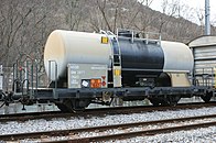
Tank car of the MGB. The brake gear is on the right axle.

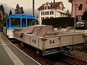
Ballast wagon of the Zugspitzbahn . The cab for the brakeman indicates that it is used as an introductory car.
Arth-Rigi-Bahn presentation car . There is only one bumper at the end of the trolley on the mountain side.


_(18682928518).jpg)
.jpg)
Safety and Brakes
The construction and operation of the cogwheel and other railways are regulated in Switzerland by the Railway Ordinance and the implementing provisions for it. Because there are no detailed rules for rack railways in other countries, almost all railways and authorities around the world accept the Swiss regulations as binding.
Admission
Because the licensing authorities outside of Switzerland only rarely have to deal with geared vehicles , it has been common for decades for the Swiss Federal Office of Transport (BAV) to carry out the new licensing of the gearwheel-related part as an expert opinion . This was then recognized by the responsible licensing authority, as is now possible with adhesion vehicles as part of a cross-acceptance procedure . Because the BAV is no longer allowed to issue expert opinions, a Swiss type approval was applied for from the BAV for the mountain locomotive 19 of the Bavarian Zugspitzbahn, which was delivered in 2016 , which was checked by an independent expert and submitted to the German Federal Railway Authority .
Brakes


The brakes play an essential role in the safety of the mountain railways. If the service brake fails, the train must be brought to a standstill with one of the mechanical reserve systems with at least 0.3 m / s² . A train unbraked for only a few seconds would be tremendously accelerated because of the downhill drift and could very quickly no longer be kept under control. The short reaction time makes it impossible to use control valves according to the UIC standard.
If the gradient exceeds 125 ‰, rack-and-pinion vehicles must be equipped with at least one inertia brake and two independent stopping brakes. In the case of traction vehicles with bogies , the two independent stopping brakes are designed as gear brakes or brakes on the motor shaft and as gear brakes (see figures in the section on electric and diesel-electric traction vehicles ), one of which must be continuously adjustable. The other serves as an "emergency brake" and has to bring the train to a standstill without the brakes of any attached wagons working. However, the buffer forces at the Zugspitze must not be too great to avoid derailment. To avoid excessive braking forces, both brake systems must be prevented from responding. Vehicles for mixed adhesion and cogwheel traffic are also equipped with an adhesion brake. On inclines of no more than 125 ‰, the automatic brake of the entire train can be used as an adjustable stopping brake or the non-adjustable stopping brake can be supported by the resistance brake .
The inertia brake includes recuperation brakes , engine brakes , hydraulic brakes and counter-pressure brakes . A catenary-independent resistance brake allows the route to be cleared in the event of a power failure. The mechanical brake cannot normally be designed as an inertia brake because the potential energy of the train to be converted into heat would thermally overload the brakes. The inertia brakes must also work if the power supply or the diesel engine fails. Each stopping brake must alone be able to bring the train to a standstill on the greatest incline with the maximum train weight. The braking forces are an important factor in safety against derailment. As stop brakes inexhaustible on new vehicles coming spring - band brakes are used.
In the case of unilateral slopes, a stopping brake is often built as a direction-dependent ratchet brake. It only brakes when going downhill. When driving uphill, the applied ratchet brake is released by a ratchet mechanism and prevents the train from rolling backwards. When going downhill, the released ratchet brake can be used as a normal brake at any time.
That the rack is at least as important for braking as it is for going uphill was shown in 1995 and 2005 when a Ge 4/4 III adhesion locomotive of the Rhaetian Railway climbed the 110 ‰ steep Oberalp Pass under its own power. To be on the safe side, a cogwheel locomotive at the rear was given for braking. Traction vehicles for adhesion sections with a gradient of more than 60 ‰ are equipped with magnetic rail brakes or eddy current rail brakes.
The gear brakes of the railroad cars are described in the section Engaging the gear wheels in the rack .
Self-excited inertia brake for converter vehicles

L: input filter choke , C: input filter capacitors , R: braking resistors , B: braking chopper , SR converter , ASM: asynchronous traction motor
At first there was hesitation in building gear-wheel vehicles with a three-phase converter drive . If a converter or its control electronics had failed, the train would have stopped with mechanical brakes on a slope and a reserve service vehicle would have to be requested. Because illegal long line occupancy and routes -führung often in uninhabited and inaccessible areas we did not address this risk.
The solution is to disconnect the traction motors from the converter in the event of a fault and to connect each phase of the three-phase asynchronous motors to an RC circuit . The three RC circuits consist of the braking resistors that are already present and the input filter capacitors of the converter. As soon as the motors start turning, they excite themselves and generate a braking force. This electric brake cannot be regulated. Your speed stabilizes at values depending on the gradient and the weight of the train. The mechanical brake is used to stop. The circuit is to be designed so that the train travels downhill a little slower than in normal operation. This self-excitation circuit, which is also used in small power plants, was tested in test runs with the JB He 2/2 10 of the Jungfrau Railway in 1992 and was first used in 1995 on the He 2/2 31 and 32 of the Wengernalp Railway.
Derailment safety


In gear operation, the vehicle can only be braked by engaging the toothed rack. The meshing of the teeth must therefore be guaranteed under all possible conditions such as strong cross winds , different coefficients of friction , emergency braking or failure of the brake in a train part. The forces that occur when braking during the descent load the front wheel sets and relieve the rear wheel sets. Together with the tooth lift, the relief of the rear wheelset can exceed the weight force during heavy braking and lift the vehicle off the rails. Because this dangerous situation must be prevented, the brakes must not be too strong.
In the case of racks with vertical tooth engagement, poor lubrication results in a force directed perpendicular to the rail plane, the tooth lift. It has the tendency to lift the vehicle off the rails and must never overcome the weight of the vehicle. The rack must be well lubricated so that the risk of derailment does not become too great.
In the case of pushed and pulled trains, the length of the trains is limited. The load of the train exerts a force on the locomotive at the height of the coupling . This longitudinal force and the difference in height between the coupling and the rack produce a torque on the traction vehicle which, in addition to the tooth lift, relieves it on the mountain side and can impair safety against derailment. In tight bends, this risk is exacerbated by lateral forces. In these situations, the formation of trains with rigid central buffer couplings such as type + GF + or Schwab is more advantageous than the compensating coupling used by the Matterhorn-Gotthard Railway with central buffers attached to the car body.
In the event of a brush fire on the traction motor collector or in the event of a short circuit , excessive forces can arise which endanger the stability of the traction vehicle. To prevent this, slip clutches are installed between the traction motors and the drive gears . This device is not necessary when a three-phase motor is used because its maximum torque is known.
Originally, the derailment safety was proven using the Borgeaud method. The security must also with the superposition of critical situation, z. B. Descent in a curve with double braking and cross winds can be guaranteed. In the 1970s, due to the possibilities at the time, some simplifications, but also neglects, were made on the Borgeaud method. Today, the proof is provided with a computer calculation, with a safety factor of 1.2 being used as a rule . Borgeaud's previous method is no longer state of the art.
Track twisting in inclined track curves


The track twisting in inclined track curves, referred to as helix twisting for short, has not yet been taken into account in the regulations on derailment safety . In curved tracks, the slope of the outer rail is less than that of the inner one. If there is a bogie on such a track section, the outer wheel of the upper axle is relieved and, in extreme cases, lifted off the rail. The helix twist is negligible for gradients of up to 40 ‰. In the case of larger gradients, however, it can exceed the maximum values of the superelevation twist. If the two twists are superimposed, there is a risk of derailment, depending on the boundary conditions. In many computer programs used for track alignment, the helix twist is not taken into account.
The superposition of helical twisting and superelevation twisting could be avoided if the superelevation twisting were built in before the transition curve. Although there would be an elevation in the straight track section without centrifugal forces , the influence on the ride comfort would be small, because in mountain railways only slight elevations are built in due to the low speeds.

In the track construction of the mountain railways, not only the superelevation twisting, but also the helical twisting independent of it or the total twisting would have to be limited. In the case of existing routes, however, it is hardly possible to adapt gradients or curve radii to new regulations. In this case, the existing helix twist would have to be taken into account in the vehicle design.
Surveillance

Because if the mechanical stopping brakes are overstrained, there is a risk of the brakes failing due to the heating, it is particularly important to monitor the driving speed when driving downhill. A mechanical brake is applied and the train is stopped even if the limit is exceeded slightly. Other conditions that are important for the function of the brakes are also monitored. Overbraking through simultaneous actuation of both mechanical stopping brakes must be prevented. Railways with combined gear and adhesion operation are equipped with operating mode monitoring. Track magnets or Eurobalises monitor the rack entrances and exits to see whether the engine driver has correctly changed the regime change between adhesion and gear or vice versa on the driver's desk. With the operating mode switchover, extensive, partly safety-relevant function changes are made on the traction vehicle.
The safety control , the overspeed control, the operating mode monitoring or other technical monitoring can automatically trigger rapid braking .
Security and signal systems

The safety and signaling systems of pure cogwheel railways are adapted to the local conditions and often differ from those of the main railways . They depend on the permissible speeds, the train density and the crossing points on single-track lines. Follow-up runs of several trains on sight are often permitted (see figure on the right in the section Advantages and Disadvantages ). Because rack and pinion turnouts are generally not accessible, it makes sense to provide a clear signal against travel into wrongly positioned turnouts. Due to the low speeds in the rack sections, distant signals are often not required if the main signals are sufficiently visible. The section block usually only serves as counter-run protection . In the case of newer systems, track vacancies are usually reported via axle counters , because track circuits can be unreliable due to the sometimes small axle loads of the lightly built vehicles and the lack of tractive power transmission via the rails. These therefore tend to be soiled by lubricant residues, pollen and fallen leaves. However, there are also pure cogwheel routes with track vacancy detection by track circuits, for example the Štrba – Štrbské Pleso cogwheel railway in the High Tatras . The skepticism that has prevailed in Switzerland for many years about track vacancy detection systems with axle counters may have supported the long-standing waiver of safety systems on some cogwheel railways. However, the risk of collision is lower on rack sections than with adhesive webs. The low speeds and the form-fitting power transmission lead to shorter braking distances and with the often clearly laid out track systems, the probability increases that, in the event of a mistake, the trains can stop before a collision. The operation is more manageable, at least with pure cogwheel railways, because of the train radio with open instead of selective voice call , the railway staff is informed of all operating deviations.

The follow-up train operation with travel on the sight of pure cogwheel railways leads to adjustments in the signal systems. Because the signals on the Wengernalp Railway only specify the driving license and not the permitted speed, all routes are displayed with driving term 1 . The follow-up trips are signaled based on the busy signal with a horizontal, orange bar that is integrated in the main signal .
| Main signal | importance |
|---|---|
|
|
Driving term 1 on type L signal for follow-up train operations on the Wengernalp Railway |
|
|
Signal image for following another vehicle , inspired by the busy signal |
|
|
Signal aspect stop at signal type L for follow-up train operation |
When leaving the station, an axle counter records the total number of axles on all subsequent trains. At the exit signal, the following train is shown the signal for a follow-up journey. At the next station, an axle counter counts the incoming axles. Only when the total number of axles has arrived can the permit be changed to enable the route for trains in the opposite direction. This means that there is no need to signal subsequent trains on the trains themselves.

With the ZSI 127 train control system, a system has existed since 2003 that covers the safety requirements of mixed adhesion and cog railways. The adhesion / rack operating mode monitoring system is integrated in the ZSI 127 train protection system and the speed monitoring is carried out with an accuracy of ± 1 km / h. ZSI 127 is built up with ETCS components, in particular with Eurobalises , Euroloops and ETCS on- board devices . A control unit in the driver's cab in accordance with the ETCS standard ( Driver Machine Interface ) had to be dispensed with because there is often not enough space in the narrow driver's cabs of narrow-gauge vehicles. Because of the rack in the center of the track, the balises are off-center. ZSI 127 is used by the Zentralbahn and the Bernese Oberland Railway . In 2013, the Federal Office of Transport established a further development of the ZSI 127 system as the standard for all Swiss narrow-gauge railways, including those with a pure adhesion drive.
| function | ZSI 127 | ETCS level 1 |
|---|---|---|
| Operating mode monitoring adhesion / rack | integrated | unavailable |
| Speed gradation | 1 km / h | 5 km / h |
| Driver's cab signaling | no (only control and display device) | yes ( Driver Machine Interface ) |
| Position of Eurobalises | off-center (for rack railways) | in the middle between the two rails |
| Early departure with a signal indicating a stop | even after turning | only with a loop or additional balises, not after turning |
business


The operation of tracks with mixed adhesion and gear drive does not differ fundamentally from pure adhesion tracks. However, the regulations for train formation must be observed in order to ensure safety against derailment .
A special feature of many pure cog railways are follow-up train operations with travel on sight and simultaneous entries into a train station. In the case of cog railways with heavy traffic, it became necessary to secure single-track routes using a route block. At the same time, the follow-up train operations had to be maintained because rack and pinion trains can only be coupled to a limited extent to ensure safety against derailment. The safety systems of such railways are designed in such a way that several trains can travel freely in one direction.
The basis for the safety of the rack railways is good maintenance of systems and vehicles as well as compliance with the sophisticated technical and operational regulations.
Operating results
Mixed rack railways

The development of the operating results is shown on the basis of the well-documented Swiss mountain railways . The Visp-Zermatt- and Berner Oberland-Bahn were decidedly tourist railways and paid out respectable dividends until 1913 , which reached 7 to 8 percent in the best years. The Brünigbahn Lucerne – Interlaken, the Stansstad-Engelberg-Bahn and the Aigle-Leysin-Bahn opened up tourist destinations and were profitable . The other mixed cogwheel railways in Switzerland, on the other hand, had temporary or permanent financial problems even before the First World War. The Bex-Villars-Bretaye railway and the Leuk-Leukerbad railway , which was discontinued in 1967, were dependent on subsidies from their own electricity works.
From 1914 the financial situation of all railways darkened rapidly. The business became deficit and did not recover in the 1920s either. The balance sheet of many railways had to be restructured, with significant parts of the share capital being written off . The Brig-Furka-Disentis Railway , which went into operation in 1915, was always in financial difficulties and went bankrupt in 1924 . Its successor, the Furka-Oberalp-Bahn , was also given military importance. But financially, even after the renovation in 1925, things never looked good with her.
After the Second World War , the St. Gallen-Gais-Appenzell Railway merged with the Altstätten-Gais Railway . The Monthey-Champéry-Morgins-Bahn and in 1961 the Schöllenenbahn also merged with neighboring companies and benefited from the federal support set out in the Private Railway Aid Act. In Germany, the St. Andreasberger Kleinbahn and the Honau – Lichtenstein cog railway were shut down. The Stansstad-Engelberg-Bahn with the Loppertunnel was structurally renovated in 1964 , the Furka-Oberalp-Bahn with the Furka Base Tunnel in 1982 and the Lucerne-Stans-Engelberg-Bahn with the Engelberg Tunnel in 2010 . In Austria, the neighboring communities took over the Achenseebahn in 1979 and rehabilitated the flat line with the help of the federal and state governments .
Today, the mixed rack railways in Switzerland, like the other regional passenger railways, are dependent on compensation . Only the BVZ and WAB railways leading to the car-free tourist resorts of Zermatt and Wengen would generate profits even without subsidies. In Germany, the Wendelsteinbahn is dependent on compensation payments. The Bayerische Zugspitzbahn, which is affiliated to the Garmisch-Partenkirchen municipal utility, generates smaller profits thanks to the mountain route, which is characterized by tourism. Through mergers can synergies be used and costs are saved. Four meter-gauge railways in western Switzerland have been operating under the umbrella of Transports Publics du Chablais since 1999 . The Matterhorn-Gotthard-Bahn , established in 2003, runs on a network of 144 km, the Zentralbahn , formed in 2005, is 98 km in length. The Appenzeller Bahnen , which has existed since 2006, operates rack railways with three different gauges.
Pure cog railways

_(4445203428)_(2).jpg)
The construction costs of the pure rack railways built between 1871 and 1912 were usually set too low, but the frequency numbers exceeded expectations. The return was generally good until the turn of the century . The Vitznau-Rigi-Bahn was extraordinarily successful, achieving an annual return of around 13 percent on average from 1871 to 1890.
The competition that arose from further new buildings reduced profits . The Arth-Rigi-Bahn could not build on the financial success of the Vitznau-Rigi-Bahn and there were practically no dividends . The Generoso , Brienz-Rothorn and Brunnen-Morschach railways were financially close to the abyss until the beginning of the Second World War. The Rorschach-Heiden mountain railway survived the war and crisis years comparatively well only thanks to the freight traffic. The Pilatus , Gornergrat and Jungfrau Railways were the most expensive railways in Switzerland in terms of fare per kilometer. Because of their exorbitant fares compared to the income at the time, the first two railways mentioned were able to distribute dividends of 4 to 7 percent of the share capital every year until 1913 . The interest burden of the extremely high construction costs of the Jungfrau Railway made only modest dividends possible. The additional investments made by many railways for electric traction reflect the optimism that prevailed in the tourism industry before the First World War.
The two world wars and the crises in between hit the tourist railways with great severity and the operating results slipped deep into the red. In Austria the Kahlenbergbahn and the Gaisbergbahn had to give up after the First World War, in Switzerland the passenger traffic of the Brienz-Rothorn-Bahn was stopped. A glimmer of hope was the emerging winter sport , which increased the number of passengers, but required extensions for winter operations. After the Second World War, the Petersbergbahn and the Barmer Bergbahn had to stop operating in Germany, and the Niederwaldbahn was replaced by a gondola lift .
Today the financial situation of the individual companies is different. The Pilatus webs achieved an average 2011-2016 cash flow of 6.6 percent, the virgin track set of 6.2 percent. The Jungfrau Railway benefits from the majority of passengers from Asia who travel to the Jungfraujoch even in bad weather. The other railways, also in Germany and Austria, make little or no profit. Around the turn of the millennium, it was examined whether the Arth-Rigi-Bahn and part of the Wengernalpbahn could be replaced by cheaper cable cars.
Accidents
Despite the considerable risk potential due to the great gradient, rack and pinion railways are a very safe means of transport today. There have been several serious accidents with multiple fatalities in the past. In 1883, a coal train rolling back derailed on the works railway in Salgótarján (Hungary) because the teeth of the drive gear of the locomotive of a train traveling uphill broke. In 1907, a freight train traveling down the valley derailed from the Brohltalbahn with passenger transport and fell down a railway embankment. In 1958, the railway accident on the Drachenfels , which was due to an operating error by the locomotive staff, claimed 18 lives. In 1964 a train on the Rittner Bahn descending into the valley derailed in South Tyrol due to poor maintenance of the superstructure and vehicles. In 1967, the locomotive derailed a downhill running train of the Mount Washington Cog Railway and fell sideways, and then the fully occupied Vorstellwagen unabated until the derailment drove.
history
prehistory
The invention of the gear drive for railways goes back to the beginnings of steam locomotives :
In 1804 Richard Trevithick built the world's first steam locomotive for the Merthyr Tramroad at the Pen-y-Darren Ironworks near Merthyr Tydfil in Wales , Great Britain . However, this locomotive was too heavy for the cast-iron rails, which were designed for wagons pulled by horse-drawn carts. Since the rails kept breaking, operations were stopped after a few months.
.jpg)
.jpg)

In 1811, John Blenkinsop was granted patent number 3431 in England for his invention of driving steam locomotives using toothed wheels that meshed with toothed racks that were attached to the outside and parallel to the rail. The first rack railway in the world was not designed by him to overcome steep gradients, but as an industrial railway ran from the coal mine in Middleton to Leeds in England. It started operations on August 12, 1812.
In 1814, George Stephenson built the Blücher locomotive for the Killingworth coal mine, which had steel wheels with a flange and was driven on steel rails by adhesion alone . From then on, this system became generally accepted.

In 1848 a 60 ‰ steep line of the Madison & Indianapolis Railroad was put into operation, for which the American Andrew Cathcart developed a cast iron lamellar rack and a corresponding locomotive. The Cathcart rack was laid in the middle of the track and anticipated the lamellar rack that is common today. The system proved itself for twenty years, until such inclines could be overcome with ordinary locomotives. In 1868 the line was switched to adhesion operation with a specially designed locomotive.
The principle of the gear drive was taken up again when nature was opened up for tourism in the 1860s and railways were supposed to climb mountains.
Railways on Mount Washington and Rigi


The world's first mountain railway with a cogwheel drive was built by Sylvester Marsh in 1866 . It climbs Mount Washington , New Hampshire , USA and opened in 1869. The railway with a track width of 1422 millimeters is still in operation today, overcomes a height difference of 1097 meters over a length of 4.8 km and has a remarkably large maximum gradient of 374 ‰.
Niklaus Riggenbach , originally from Alsace , received a first patent for his rack railway in France in 1863. He traced the invention back to his experience as the technical manager of the Hauenstein line with a 26 ‰ gradient, where the spinning of the drive wheels could not always be prevented even with sand spreading . In 1869 he learned that Marsh was building a cogwheel train up Mount Washington. The Vitznau-Rigi-Bahn , designed by Riggenbach, opened on May 21, 1871 and is the first mountain railway with a cogwheel drive in Europe. It leads with a maximum gradient of 250 ‰ from Vitznau in Switzerland on Lake Lucerne to the Rigi . The railway initially ended at the Lucerne canton border, as the concessions were granted by the cantons at the time. Only two years later did it reach today's end point, Rigi Kulm. Riggenbach was also concerned with the construction of the Rigibahn to demonstrate the advantages of the rack railway over adhesion railways . His proposals, through the Alps such as the planned Gotthard Railway to build a cog railway, however, proved to be miscalculation. The works railway to the Ostermundigen quarry, also constructed by Riggenbach, was opened on October 6, 1871. However, the start of operations is controversial.
Rise of the rack railways

The Rigibahn was a resounding technical and commercial success. It initiated an upswing in the construction of rack railways at the beginning of the 1880s. The first rack railways in Austria-Hungary were the Kahlenbergbahn near Vienna , which opened on March 7, 1874, and the Schwabenbergbahn in Budapest, which began operating on June 24, 1874. The Rorschach-Heiden mountain railway in Eastern Switzerland was opened to traffic on September 6, 1875 as the first cogwheel railway with non-tourist passenger traffic.
The first cogwheel railway in Germany was the cogwheel railway of the Wasseralfingen ironworks , which went into operation in 1876 . The two subsequent cog railways, the Friedrichssegen mine near Bad Ems on the Lahn and the Kunst mine near Herdorf in Siegerland, were mine railways . In 1883, the Drachenfelsbahn, the first public cogwheel railway, went into operation, which is still in operation today. It has a slope of 200 ‰.
By the time of the First World War, a total of more than a hundred rack railways were put into operation, most of which were in Europe. The world's steepest cog railway with a maximum gradient of 480 ‰ is the Pilatusbahn , which opened in 1889 and leads from the shores of Lake Lucerne to the Pilatus. For this train, Eduard Locher developed a special gear system named after him.
The first rack railways were operated exclusively with steam locomotives . In the course of the 1890s, electric traction was introduced , which quickly gained in importance. After the First World War, there was a decline in the number of cog railways because cogwheel operation was replaced by adhesion drives or because traffic was discontinued. Many railways, which were originally powered by steam, have been electrified, with some of the steam locomotives being replaced or supplemented by diesel traction vehicles . The renewal of the rolling stock over the years has increased the efficiency and attractiveness of the modernized rack railways, as some examples show:
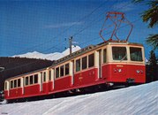
The Štrba – Štrbské Pleso rack railway in the High Tatras in Slovakia was canceled in 1931, but reopened in 1970.

The world's first cogwheel railcars with diesel-hydraulic drive came into operation at the Pike's Peak Railway in Colorado in 1976 .

The Corcovado mountain railway in Rio de Janeiro started operating with new railcars after a complete renovation in 1979.

In 1992 the Schafbergbahn received new steam locomotives 999.2 to increase the tourist attractiveness.

Since 1999, travel on the snow-mountain-bahn Salamander trains with diesel-hydraulic locomotives Hunslet-Barclay Ltd .
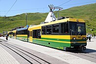
In 2004, the Wengernalp Railway in the Bernese Oberland procured panorama rack-and-pinion railcars .
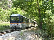
The rolling stock on the Diakopto – Kalavryta line in the Peloponnese was modernized in 2007 with four BDmh 2Z + 4A / 12 diesel multiple units .

The Panoramique des Dômes in France, which was discontinued in 1925 and reopened in 2012, uses Stadler cogwheel GTWs .


.jpg)

In the 20th century, new cogwheel routes were created through the rebuilding and expansion of funicular railways , such as the Lausanne – Ouchy cogwheel railway , the Dolder railway in Zurich or a tunnel in Lyon, which is now integrated into the urban Métro network. In 1987, the Perisher was opened to traffic in Australia in 1987 to open up a ski area. In 1990, due to the construction of a dam, a section of the Ikawa line , which had previously been operated as a pure adhesion railway, was relocated and provided with a rack.
In contrast, since the 1920s, many routes with rack sections with inclines of up to about 70 ‰ were switched to pure adhesion operation. It was made possible by advances in locomotive construction, higher axle loads due to a more stable superstructure and the widespread use of continuous, automatic and multi-release compressed air brakes . The Halberstadt-Blankenburg Railway provided pioneering achievements in this area with its Blankenburg – Tanne line (at the time the "Harz Railway", later called the Rübeland Railway ). Even as mine and industrial railways, there are no longer any cog railways. They were replaced by conveyor belts and trackless conveyors.
See also
literature
- Walter Hefti : The world's rack railways. Birkhäuser, Basel 1971, ISBN 3-7643-0550-9 .
- Walter Hefti: The world's rack railways. Addendum. Birkhäuser, Basel 1976, ISBN 3-7643-0797-8 .
- Beat Keller: Rack Railways - A Guide for Project Planning . In: Swiss Railway Review . No. 4-5 . Minirex, 1991, ISSN 1022-7113 , pp. 115-135 .
- Dolezalek: toothed tracks. In: Enzyklopädie des Eisenbahnwesens , edited by Victor von Röll , Volume 10. Berlin and Vienna 1923, pp. 451–468. (Zeno.org)
- Dolezalek: mixed courses. In: Enzyklopädie des Eisenbahnwesens , edited by Victor von Röll, Volume 5. Berlin and Vienna 1914, pp. 272–273. (Zeno.org)
- Alfred Moser: The steam operation of the Swiss railways 1847–1966. Birkhäuser, Basel 1967, pp. 353–385
- Žarko Filipović: Electric railways: basics, locomotives, power supply. Springer-Verlag, 2004, ISBN 978-3-540-55093-8 . Pp. 203-212
- Rudolf Schmid: The rack railway as a modern means of transport. In: Schweizer Ingenieur und Architekt , Volume 97 (1979), Issue 23 (E-Periodica.ch, PDF; 3.5 MB).
- Rolf Honegger: 100 Years of the Brünigbahn - Die Zahnradtechnik In: Schweizer Ingenieur und Architekt , Volume 106 (1988), Issue 40 (E-Periodica.ch, PDF; 1.1 MB).
- Racks. In: Internet site of Tensol Rail, Giornico. Retrieved July 15, 2017 .
- Wolfgang Messerschmidt: Rack railways, yesterday, today, all over the world. The history of the rack railways , Franckh, Stuttgart 1972, ISBN 3-440-03833-5
-
Karl Sachs : 50 years of Swiss electric mountain railways. In: Schweizerische Bauzeitung (SBZ). (archived in E-Periodica of the ETH-Bibliothek):
First part. In: SBZ, Volume 66 (1948), Issue 50 (PDF, 4.2 MB)
Conclusion. In: SBZ, Volume 66 (1948), Issue 51 (PDF, 5.0 MB) - Thomas Fleißig: Rack railways in Austria. Railway picture archive. EK, Freiburg 2004, ISBN 3-88255-349-9 .
- Arthur Meyer, Josef Pospichal: Rack railway locomotives from Floridsdorf , Verlag bahnmedien.at, Vienna 2012, ISBN 978-3-9503304-0-3 .
- Theo Weiss: Stadler - from the tunnel locomotive to the double-decker train. Minirex, Lucerne 2010, ISBN 978-3-907014-33-2 , pp. 104-109
- Klaus Fader: Cog railways in the Alps. 19 mountain railways in Germany, France, Austria and Switzerland. Franckh-Kosmos , Stuttgart / Ott, Thun 1996, ISBN 3-440-06880-3 / ISBN 3-7225-6346-1 (Ott); Tosa, Vienna 2003, ISBN 3-85492-791-6 .
- Werner Latscha (Ed.): Seven mountain railway pioneers. Swiss pioneers in business and technology, No. 81. Association for Economic History Studies, Zurich 2005, ISBN 978-3-909059-34-8 .
- Josef Hons: Mountain railways in the world. Rack railways, rail and funicular railways, suspension railways and ski lifts. transpress-Verlag, Berlin 1990, ISBN 3-344-00475-1 .
- Rack and pinion tracks. In: Lexicon of the entire technology and its auxiliary sciences , edited by Otto Lueger, Volume 8. Stuttgart and Leipzig 1910, pp. 962–965. (Zeno.org)
Web links
- Matthias Probst: On cogwheels into the mountains. In: Swiss Radio and Television (SRF) website , with a 4:45 min film excerpt from the Einstein broadcast on May 30, 2013.
- Jens Merte: Rack railways in Germany. Retrieved July 15, 2017.
Individual references and comments
- ↑ a b c d e f g h i j Peter Schmied: 34th conference “Modern Rail Vehicles” in Graz (continuation) . Hans Schlunegger (Jungfrau Railways): Modern rack railways. In: Swiss Railway Review . No. 2 . Minirex, 2003, p. 66 .
- ↑ a b Implementing provisions for the Railway Ordinance (AB-EBV) DETEC , November 1, 2020 (PDF; 9 MB)
- ↑ a b c d Kilian T. Elsasser, Swiss Museum of Transport (ed.): Gnom . Niklaus Riggenbach - The mountain railway pioneer and his cogwheel steam locomotive «Gnom». AS Verlag, Zurich 2002, ISBN 3-905111-80-2 .
- ^ Hans-Peter Bärtschi , Anne-Marie Dubler : Railways - 3.3 - branch lines. In: Historical Lexicon of Switzerland . February 11, 2015 , accessed June 4, 2019 .
- ^ A b c d Walter von Andrian: New mountain route to Engelberg . In: Swiss Railway Review . No. 5 . Minirex, 1995, p. 189-194 .
- ↑ Implementing provisions for the Railway Ordinance (AB-EBV) DETEC , November 1, 2020 (PDF; 9 MB). AB 76.1.a Maximum speed depending on the decisive incline , item 9
- ^ A b Walter von Andrian: Diesel-electric gear / adhesion locomotives for Indonesia. In: Swiss Railway Review , No. 1–2. Minirex, 1994, pp. 10-11.
- ↑ a b Michael Burger, Jürg Schöning: The largest cogwheel locomotive in the world for the Paranapiacaba - Raiz da Serra line operated by MRS Logística . In: Swiss Railway Review . No. 4 . Minirex, 2014, pp. 176-181 .
- ↑ Beat Keller: Rack Railways - A Guide for Project Planning, pp. 134–135
- ↑ Žarko Filipović: Electric Railways: Basics, Locomotives, Power Supply, p. 205
- ↑ a b c d e Hans Schlunegger: Modern double multiple units BDhe 4/8 211 −214 for the Jungfrau Railway . In: Swiss Railway Review . No. 12 . Minirex, 1992, pp. 549-557 .
- ↑ Rack lubrication - practical experience (PDF; 113 kB) , Ernst Zbinden at the 2010 Rack Railways Conference in Brig, accessed on October 29, 2012
- ↑ a b c d Peter Berger: Documentation of rack railway technology based on archival and empirical knowledge In: Ferrum: News from the Iron Library, Foundation of Georg Fischer AG , Volume 86, 2014 (E-Periodica.ch, PDF; 10.7 MB) .
- ↑ a b Walter Hefti: rack railways of the world , p. 156
- ^ Necrologist - Arnold Pauli. In: Schweizerische Bauzeitung , Volume 105 (1935), Issue 12 (E-Periodica.ch, PDF; 0.4 MB).
- ↑ a b Emil Strub: Wengernalp Railway (continued). In: Schweizerische Bauzeitung , Volume 22 (1893), Issue 9 (E-Periodica.ch, PDF; 4.4 MB).
- ↑ a b c Josef Hardegger: 100 Years of the Gaiserbahn, 1889–1989. Verlag Schläpfer, Herisau 1989, ISBN 3-85882-063-6 . Pages 113–114
- ^ Kilian T. Elsasser: Restoration of the cogwheel steam locomotive Gnom in the Swiss Museum of Transport, January 2000 to March 2002. Swiss Society for the History of Technology and Industrial Culture, October 2000
- ↑ a b E. E. Seefehlner, HH Peter: Electric train conveyance: Handbook for the theory and application of electric traction on railways. Springer Verlag, 1924, pp. 547-548
- ^ Siegfried Abt: Contribution to the history of the caliper brakes. In: Schweizerische Bauzeitung, Volume 48 (1906), Issue 22 (E-Periodica.ch, PDF; 4.1 MB).
- ^ A b Association of public transport (ed.): D RTE 29700 Systemtechnik rack railways documentation . March 31, 2010
- ↑ Exit from Abbot Ichishiro with Abbot rack Photo in Wikimedia, December 16, 2007
- ↑ Dolezalek: toothed tracks , chapter stepped racks , type Abt.
- ↑ Twenty-five year anniversary of the System Dept. In: Schweizerische Bauzeitung. Volume 50 (1907), issue 10 (E-Periodica.ch, PDF; 0.4 MB).
- ↑ Fritz Balmer: From accident to low frequency high. General assembly of the Berner Oberland-Bahnen AG. In: Jungfrau Zeitung , June 17, 2004
- ↑ a b The term "climbing up" is used twice: 1. The flanks of the racks are inclined, which is why the transmitted force acting parallel to the direction of travel has a component in the direction of the flank. If the counterforce from the weight of the vehicle is insufficient, the teeth of the toothed wheel slip out of the rack. The vehicle is raised together with the gear. 2. The heads of the teeth meet and roll off each other.
- ^ Siegfried Abt: The new unified friction and tooth path system Peter. In: Schweizerische Bauzeitung , Volume 71 (1918), Issue 1 (E-Periodica.ch, PDF; 2.8 MB) and Volume 71 (1918), Issue 2 (PDF; 2.6 MB).
- ^ Emil Strub: On the 25th anniversary of the Rigibahn (II.) In: Schweizerische Bauzeitung , Volume 27 (1896), Issue 23 (E-Periodica.ch, PDF; 5.4 MB).
- ↑ Implementing provisions for the Railway Ordinance (AB-EBV) DETEC , November 1, 2020 (PDF; 9 MB). AB 33.1 point 5 racks of rack railways
- ↑ Implementing provisions for the Railway Ordinance (AB-EBV) DETEC , November 1, 2020 (PDF; 9 MB). AB 54.2.b.1 Rack with vertical tooth engagement , section 1.7
- ↑ a b Sébastien Jarne, Klaus Potocnik, Hans Schlunegger: New freight locomotives 31 and 32 of the Wengernalp Railway . In: Swiss Railway Review . No. 3 . Minirex, 1996, pp. 92-103 .
- ^ Andreas Meier, Urs Wieser, Anton Zimmermann: Diesel-electric cogwheel and adhesion locomotive and snow thrower for the cogwheel railway Ribes - Nuria . In: Swiss Railway Review . No. 4 . Minirex, 1995, p. 157-164 .
- ↑ Beat Keller: Rack Railways - A Guide for Project Planning, pp. 125–126
- ↑ a b c Beat Feusi, Reinhard Zuber, Gerhard Züger: New cogwheel multiple units ABeh 150, ABeh 160 and ABeh 161 for the Zentralbahn . Continuation from issue 3/2017. In: Swiss Railway Review . No. 4 . Minirex, 2017, p. 192-199 .
- ^ Alfred Moser: The steam operation of the Swiss railways 1847-1966 , p. 383
- ^ SUST final report on the derailment of a passenger train from June 5, 2016. Swiss Security Investigation Board (SUST), March 21, 2017
- ↑ ( Swiss Driving Service Regulations (FDV) A2020 Federal Office of Transport (BAV), July 1, 2020 (PDF; 9 MB). R 300.13, Section 13.2 Post- brake for mixed cogwheel / adhesive railways )
- ^ A b Peter Berger, Hans Waldburger, Christoph Berger: Railways to Engelberg. 100 years of rail transport from Lake Lucerne to the monastery village. Minirex, Lucerne 1998, ISBN 3-907014-10-3 .
- ↑ Peter Schoch, Martin Stamm, Herbert Welte: The new panorama cars A 102 and 103 for the Brünigbahn. In: Swiss Railway Review , No. 10. Minirex, 1994, pp. 447–485.
- ↑ Peter Fehr: New rolling stock e.g. The new generation of rack and pinion trains. Documents for the TST conference of the Association of Public Transport, November 2, 2012. PDF; 3.5 MB. ( Memento from August 19, 2017 in the Internet Archive )
- ↑ Rack entrances. In: Internet site of Tensol Rail , Giornico. Retrieved November 15, 2017.
- ↑ Swiss Driving Regulations (FDV) A2020 Federal Office of Transport ( FOT ), July 1, 2020 (PDF; 9 MB). R 300.2, section 2.3.6 Signals for rack
- ↑ a b Emil Strub: Wengernalpbahn (end). In: Schweizerische Bauzeitung , Volume 22 (1893), Issue 10 (E-Periodica.ch, PDF; 5.3 MB).
- ↑ Walter Hefti: Rack Railways of the World, p. 36
- ↑ a b Peter Pfenniger: New special bendable rack and pinion turnout RIGI-VTW 2000. Rigi Bahnen, in February 2001; accessed on July 15, 2017.
- ^ Hans G. Wägli: Rail network Switzerland - Réseau ferré suisse. AS Verlag, Zurich 2010, p. 72
- ↑ a b c d e f g h i j Karl Tillmetz, Hermann Patrick Braess: The helix twist - a critical influencing factor in the routing and layout of mountain railways (continued from issue 12/2020) . In: Swiss Railway Review . No. 1 . Minirex, 2021, pp. 52-54 .
- ↑ a b c Hans Tribolet: The new multi-purpose locomotives HGe 4/4 II 1 - 5 of the Brig - Visp - Zermatt Railway. In: Swiss Railway Review . No. 10 . Minirex, 1990, pp. 263-270 .
- ^ Rudolf Schmid: The rack railway as a modern means of transport, p. 441
- ↑ a b Dolezalek: rack tracks , chapter locomotives
- ^ A b Karl Sachs: 50 years of Swiss electric mountain railways. In: Schweizerische Bauzeitung , Volume 66 (1948), Issue 50 (E-Periodica.ch, PDF; 4.2 MB) and Volume 66 (1948), Issue 51 (PDF; 5.0 MB).
- ^ Hans Schlunegger: New double multiple units BDhe 4/8 211-214 of the Jungfrau Railway . In: Swiss Railway Review . No. 9 . Minirex, 1989, pp. 207-208 .
- ↑ GGB railcar delivered . In: Swiss Railway Review . No. 12 . Minirex, 2006, p. 585 . and Heinz Inäbnit, Urs Jossi: New and renewed multiple units for the Jungfrau Railway . In: Swiss Railway Review . No. 4 . Minirex, 2016, p. 180-182 .
- ↑ Jürg D. Lüthard: New locomotive for the Bavarian Zugspitzbahn . In: Swiss Railway Review . No. 12 . Minirex, 2014, pp. 599 .
- ↑ L. Degen: New locomotive for the Mount Washington Cog Railway. In: Swiss Railway Review , No. 4. Minirex, 2018, p. 208.
- ↑ Hans Schneeberger: The electric and diesel traction vehicles of the SBB. Volume I: years of construction 1904–1955. Minirex AG, ISBN 3-907014-07-3 . P. 269
- ↑ Four-cylinder cogwheel and adhesion locomotive of the Brünigbahn (Swiss Federal Railways). In: Die Lokomotive , 1906, pp. 21–22 ( ANNO - AustriaN Newspapers Online )
- ↑ A. Ostertag: On the development of the steam locomotives of the Swiss railways. In: Schweizerische Bauzeitung , Volume 65 (1947), Issue 25 (E-Periodica.ch, PDF; 7.0 MB).
- ↑ Tadej Brate: Slovenske muzejske locomotive. Slovenian museum locomotives. Verlag mladinska knjiga, 2004, ISBN 86-11-16904-2 , (Slovenian). Page 38
- ^ Siegfried Abt: The new locomotives of the state railways on Sumatra (west coast) . In: Schweizerische Bauzeitung. Volume 78 (1921), Issue 7 (E-Periodica.ch, PDF; 2.1 MB).
- ^ Siegfried Abt: The new locomotives of the Nilgiri Railway. In: Schweizerische Bauzeitung. Volume 70 (1917), Issue 7 (E-Periodica.ch, PDF; 1.7 MB)
- ^ Raimar Lehmann: Steam locomotive special designs. Springer, Basel, ISBN 978-3-0348-6757-3 , p. 183
- ^ Martin Gerber, Walter Hürlimann, Peter Maurer: New locomotives HGe 4/4 II for the Brünig line of the SBB and for the Furka-Oberalp-Bahn . In: Swiss Railway Review . No. 6 . Minirex, 1985, pp. 183-195 .
- ^ Walter von Andrian: Generation leap in the Brünigbahn rolling stock. In: Swiss Railway Review , No. 6. Minirex, 2009. pp. 320–321.
- ^ A b Hans Waldburger: 125 years of Rorschach - Heiden-Bergbahn (RHB) (Part 6) ( Memento from February 18, 2005 in the Internet Archive ). In: Swiss Railway Amateur Club Zurich (SEAK) , 2000
- ^ Freight wagons. On the website of the Furka Mountain Route Steam Railway , accessed on December 28, 2020.
- ↑ Implementing provisions for the Railway Ordinance (AB-EBV) DETEC , November 1, 2020 (PDF; 9 MB). AB 54.2.b.3 Braking of wagons , paragraphs 1.1.1 and 3.1
- ↑ Mathias Rellstab: The cogwheel giant is born. In: Swiss Railway Review. No. 4. Minirex, 2012, p. 193.
- ↑ Implementing provisions for the Railway Ordinance (AB-EBV) DETEC , November 1, 2020 (PDF; 9 MB). AB 54.2.b.4 Braking when pulling wagons , section 1.2
- ↑ Implementing provisions for the Railway Ordinance (AB-EBV) DETEC , November 1, 2020 (PDF; 9 MB). AB 54.2.b.4 Braking when pulling wagons , item 1
- ↑ One-sided inclined rack railways in the German-speaking countries with push-pull trains whose locomotives are lined up on the valley side: Altstätten – Gais (AB), Rorschach – Heiden (AB), Jungfraubahn , Arth – Rigi (RB), Vitznau – Rigi (RB), Wengernalpbahn , Lucerne -Stans-Engelberg-Bahn (until 2010), Gornergratbahn , Schöllenenbahn (MGB), Martigny – Châtelard (TMR), Lausanne – Ouchy (until 2006) , Blonay – Les Pléiades (CEV), Aigle – Leysin (TPC), Aigle– Champéry (TPC), Bex – Villars (TPC), Zugspitzbahn and Schneebergbahn . The links point to a picture as evidence.
- ↑ One-sided inclined rack railways with push-pull trains, the locomotives of which are lined up on the mountain side: St. Gallen – Appenzell (AB, until 2018; Ruckhalde curve with a 30 meter radius), Berner Oberland Railway , Lucerne – Stans – Engelberg accessed on December 29, 2020 (e.g. since 2010) and Visp – Zermatt (MGB). The links point to a picture as evidence. Railways not mentioned are inclined on both sides or do not operate push-pull trains.
- ^ Association of German Railway Administrations (ed.): Basic features for the construction and operating facilities of the local railways . Berlin, January 1, 1909, §21.
- ^ Hans Waldburger: 125 years of Rorschach - Heiden-Bergbahn (RHB) (Part 3) ( Memento from February 17, 2005 in the Internet Archive ). In: SEAK , 2000
- ^ Ordinance on the construction and operation of the railways (Railway Ordinance, EBV) Swiss Confederation, 23 November 1983
- ↑ Michael Burger: Electric mountain locomotive 19 of the Bavarian Zugspitzbahn. In: Swiss Railway Review , No. 12/2017, Minirex, p. 607
- ↑ a b c Werner Hubacher, Othmar Wilhelm: The series version of the Brünigbahn locomotives HGe 4/4 101 961–968. In: Swiss Railway Review , No. 10. Minirex, 1989, pp. 231–239.
- ↑ Michael Burger: New diesel-electric locomotives Hm 2/2 and HGm 2/2 for various rack railways. In: Swiss Railway Review , No. 12. Minirex, 2011, pp. 585–593.
- ↑ a b c Martin Aeberhard, Andreas Meier, Markus Meyer: Self-excited inertia brake for gear vehicles with asynchronous drive motors. In: Swiss Railway Review , No. 4. Minirex, 1992, pp. 130–132.
- ^ Mathias Rellstab: Ge 4/4 III on the Oberalp Pass. In: Swiss Railway Review. No. 6. Minirex, 2005, pp. 260-261.
- ^ Walter von Andrian: RhB-Ge 4/4 III at the FO. In: Swiss Railway Review , No. 6. Minirex, 1995, pp. 260–261.
- ↑ Implementing provisions for the Railway Ordinance (AB-EBV) DETEC , November 1, 2020 (PDF; 9 MB). AB 52.1 Requirements for braking systems , section 9
- ↑ Žarko Filipović: Electric Railways: Basics, Locomotives, Power Supply , p. 211
- ↑ Hans Streiff: Recovery of braking energy in rail transport (Part II). ( Memento from February 20, 2005 in the Internet Archive ) In: Homepage of the Swiss Railway Amateur Club Zurich (SEAK) , 1999. ( Memento from February 20, 2005 in the Internet Archive )
-
↑ G. Borgeaud: Standstill and derailment safety in rack railways .
Schweizerische Bauzeitung, Volume 87 (1969), Issue 4 (Part 1) (E-Periodica, PDF 10.3 MB)
Schweizerische Bauzeitung, Volume 87 (1969), Issue 5 (Part 2) (E-Periodica, PDF 11.8 MB) -
↑ Gaston Borgeaud: Standstill and derailment safety in rack railways .
Schweizerische Bauzeitung, Volume 96 (1978), Issue 27/28 (Part 1) (E-Periodica, PDF 8.5 MB)
Schweizerische Bauzeitung, Volume 96 (1978), Issue 30/31 (Part 2) (E-Periodica, PDF 2.8 MB)
Schweizerische Bauzeitung, Volume 96 (1978), Issue 32 (Part 3) (E-Periodica, PDF 4.5 MB)
Schweizerische Bauzeitung, Volume 96 (1978), Issue 35 (Part 4) (E- Periodica, PDF 2.8 MB)
Schweizerische Bauzeitung, Volume 96 (1978), Issue 37 (Part 5) (E-Periodica, PDF 2.3 MB) - ↑ a b Karl Tillmetz, Hermann Patrick Braess: The helix twist - a critical influencing factor in the routing and layout of mountain railways . In: Swiss Railway Review . No. 12 . Minirex, 2020, p. 660-663 .
- ↑ a b c d Hans Schlunegger: New signal boxes on the Grindelwald - Kleine Scheidegg line of the Wengernalp Railway (WAB) . In: Swiss Railway Review , No. 2. Minirex, 2004, pp. 73–77.
- ^ Richard Meier: collisions despite train control. In: Swiss Railway Review , No. 6. Minirex, 2013, p. 275.
- ^ A b Hans Schlunegger: Train protection system ZSI 127 of the Berner Oberland-Bahnen and the Zentralbahn. In: Swiss Railway Review , No. 5. Minirex, 2005, pp. 242–245.
- ↑ BAV defines train control standards for narrow-gauge railways. In: Swiss Railway Review , No. 8–9. Minirex, 2013, pp. 242-245.
- ↑ ZSI 127. Safe on the move. In: Homepage of the Rhaetian Railway, 2014
- ↑ a b c d e f Thomas Frey, Hans-Ulrich Schiedt: bahndaten.ch. Data on the Swiss railways 1847–1920. Via Storia, Center for Transport History at the University of Bern , accessed on November 1, 2017.
- ↑ Matterhorn Gotthard Bahn: A lesson in the Valaisian style. In: Balance sheet of March 22, 2005
- ↑ Management report for the business year from November 1, 2013 to October 31, 2014. ( Memento from November 9, 2017 in the Internet Archive ) Bayerische Zugspitzbahn Bergbahn Aktiengesellschaft Garmisch-Partenkirchen (PDF; 0.8 MB)
- ↑ a b c d e Wolfgang König: Railways and Mountains. Traffic engineering, tourism and nature conservation in the Swiss Alps 1870–1939. German museum. Contributions to historical traffic research, Frankfurt / New York, 2000
- ↑ Peter Burkhardt: Mountain railways hang on the ropes. In: Tages-Anzeiger from January 8, 2017
- ↑ Asians storm the Jungfraujoch. In: 20 minutes from April 17, 2013
- ↑ Accident on a rack railway. In: Zentralblatt der Bauverwaltung , February 17, 1883 (epilog.de - time travel to culture + technology)
- ↑ Rittnerbahn. In: Homepage of the Tiroler MuseumsBahnen, accessed on September 15, 2017
- ↑ Suki Casanave: Mount Washington Cog Railway. In: New England Today , April 20, 2015
- ↑ Gernot Dietel: The model is called America. The Madison Incline in Indiana, USA, an early rack railway . In: Eisenbahngeschichte 62, pp. 71-73 with reference to: Baldwin Locomotive Works (ed.): The History of the Baldwin Locomotive Works 1831-1920 , pp. 41f.
- ^ Mayer: The first rack railways and the Riggenbach system. In: Die Lokomotive , 1943, pp. 106-108 ( ANNO - AustriaN Newspapers Online )