
History of the electric drive of rail vehicles


The history of the electric drive of rail vehicles deals with the historical processes and development steps during its introduction. In addition to the first beginnings and other trend-setting developments, the introduction in countries that have a particularly large proportion of electrically operated routes is presented.
Technical requirements
Several components were required for the development of electrically powered rail vehicles :
- a reliable electric motor
- available electrical energy in a suitable form
- a suitable drive
Motor principle

In 1820 the Danish chemist Hans Christian Ørsted discovered the phenomenon of electromagnetism . In the same year Michael Faraday published his work results on "electromagnetic rotation". He constructed a device in which an electrical conductor rotated around a fixed magnet and, in a counter-experiment, a movable magnet rotated around a fixed conductor.
In 1822 Peter Barlow developed the Barlow wheel named after him . The blacksmith Thomas Davenport developed a commutator motor in Vermont ( United States ) in 1834 and received the first patent for the electric motor on February 25, 1837.
On the European continent, Ányos Jedlik and Hermann Jacobi (1801–1874) worked in a similar way to Davenport on the development of the practical electric motor. Jacobi also equipped a six-person boat in Saint Petersburg in 1838 with a 220 watt motor that he had developed. Thus around 1837/1838 the basis for an electric motor drive was known and developed into a work machine suitable for use.
Electrical power
The electrical energy was initially only available in batteries, which had to be carried in the appropriate space and weight. From then until now, zinc has proven to be an effective and easy-to-process basic component of electrical batteries. Large quantities of zinc were mined in England as early as 1720 , zinc smelters were being built in many places, and the first zinc rolling mill was built in Belgium in 1805. The electrical energy supply was thus basically available, but it was expensive. Hermann Jacobi used a very expensive zinc-platinum battery .
The cost of an electric battery at that time was many times the value of the coal burned in a steam engine for the same work performance. With magnetic induction was, for example, as early as 1832 Hippolyte Pixii and Dal Negro in generators produces energy, but it was initially only for the operation of lamps and for electrical purposes considered usable. It was not until 1866, when the entrepreneur Werner Siemens generated electricity with the generator machines he built, that electrical energy became available in an amount and size that allowed the idea of electric motor drives to grow beyond the status of an interesting gimmick.

The only type of current available was initially direct current , which also proved to be easy to use and thus established itself as the “first choice” for many railways. The speed could be controlled simply by connecting the traction motors in series or in parallel and by using resistors as voltage dividers . In the upper speed range, the required increase in speed was achieved through field weakening . As in steam operation, the traction motors developed the highest tractive effort when approaching, with high train loads and on inclines, which turned out to be particularly favorable in rail operations.
From 1890, with the development of the three-phase system and three-phase asynchronous motor, a very simple and highly efficient drive became available. Its application, however, required the use of three-pole power supply lines, which were complex to implement, and only a few speeds that were predetermined by the mains frequency could be set. In the early days, however, many attempts were made to use three-phase current for rail operations, but on a larger scale only at the Italian Ferrovie dello Stato between 1904 and 1976.
Major role in the distribution of the electric drive with remote paths had the development of the transformer , the electrical energy made possible the economic transmission over long distances and yet the similar advantageous driving operation as the DC power supply. The associated use of high-voltage single - phase alternating current initially turned out to be problematic for motor operation, but could be adapted for rail operation with low frequencies in the range of 15 to 25 Hertz . Extensive investigations between 1905 and 1907 under the direction of Robert Dahlander at the Swedish Statens Järnvägar contributed to this finding . It involved the AEG , the Siemens-Schuckert and Westinghouse Electric , the latter in cooperation with the US Baldwin Locomotive Works .
drive
A suitable solution first had to be found for the power transmission from the electric machine to the wheels. The principle of machine-driven rail vehicles was indeed since the introduction of the steam engine by Richard Trevithick known 1804th As a result, C. G. Page used a drive with two electromagnets for his traction vehicle, which rotated the wheels in alternating back and forth motion with a crank mechanism like a piston steam engine . This line of development was not pursued any further; instead, drive systems quickly developed in which the rotating movement of an electric motor was transmitted directly or with the help of a gearbox to the drive wheels or axles of the vehicle.
Development over time
In 1835, Thomas Davenport in Vermont used the commutator motor he developed to build a model of an electrically powered track-guided vehicle on a single-track circle of four feet in diameter. His model was executed in high abstraction, it had two rails in the form of circular rings, which were mounted concentrically on two levels. The inner, lower-lying rail served as a track for the motor drive, the other rail as a pure power rail. However, this approach went largely unnoticed.
The Scot Robert Davidson (1804-1894) built an electric locomotive model in Aberdeen in 1837 or 1838 and later a larger, "Galvani" called locomotive, which was demonstrated at the exhibition of the Royal Scottish Society of Arts in 1841 and in 1842 on the railroad between Edinburgh and Glasgow was tried. The engine is said to have worked on a similar principle as in the locomotive developed in 1851 by CG Page and described below. The vehicle reached a speed of four miles per hour, but no further loads could be pulled or passengers could be carried. The zinc battery used turned out to be forty times more expensive in operation than the comparable expenditure for burning coal. It is reported that the "Galvani", which was parked in a shed, was destroyed by steam locomotive machinists in spite of its apparent inferiority due to concerns about the resulting competition. Davidson saw the opening of electrical operations on the City and South London Railway tunnel , which led him to identify himself on his business cards as “Robert Davidson. Father of the Electric Locomotive ”.
In Frankfurt am Main in 1840 Johann Philipp Wagner (the inventor of the “Wagner's Hammer” ) succeeded in driving a small car with a trailer driven by an electric motor on a circle of rails with a circumference of 20 meters. He was then commissioned to build a functioning large "electromagnetically driven" locomotive, for which he was made available an amount of 100,000 guilders. However, it failed to implement, allegedly due to a lack of knowledge about the relationship between battery capacity and drive power.


The US patent clerk Charles Grafton Page (1812–1868) began building a locomotive powered by two electric motors near Washington, DC in 1850 with a government grant of $ 20,000. The 15 kilowatt “motors” each consisted of two coils with a rod armature embedded in them, which was moved back and forth by alternately switching on the coils like in a piston steam engine . This oscillating movement was transmitted to the pair of driving wheels of a three-axle wagon with drive rods. The engines were fed by a huge, 50-element battery that brought the car to a mass of twelve tons. During the test run on April 29, 1851, this locomotive briefly reached a speed of 31 km / h, but insulation burned through and battery elements breaking under the vibrations (wet chemical in cylindrical or cuboid glass vessels were common) led to the journey being far ahead after 40 minutes had to be canceled before reaching the goal.
First attempts at application
The electric rail vehicle drive only became really suitable for use with the introduction of a fixed power supply via conductor rails or contact lines . On the tram route along the spa promenade of the Russian Baltic resort of Sestrorezk , Fyodor Pirozki experimented with this type of power supply over a kilometer in 1875. As later at Siemens in Lichterfelde, the energy was supplied via the two running rails. From August 22nd, 1880, he operated a converted double-decker horse-drawn tramway for twelve days on a horse-drawn tramway that was prepared as in Sestrorezk, which some traffic historians consider to be the world's first electric tram.


Werner Siemens built in Berlin in 1879 what was originally intended as a mine railway for Cottbus with a 500 millimeter gauge and a two-axle electric locomotive . It was supplied with power by a stationary dynamo via an insulated conductor rail mounted in the center of the track, while the running rails served as the return line of the circuit . This locomotive pulled three wagons with wooden benches mounted on them for six passengers each on a 300 meter long circuit at the trade exhibition at that time. The engine power of the locomotive was 2.2 kilowatts. Without a load, it reached a speed of 13 kilometers per hour and with the trailers each occupied by six people a speed of 6 km / h. The direction of travel was changed by a reversing gear, as the change in the direction of rotation of the motor by reversing the polarity of the winding was not yet known.
In four months 90,000 people were transported with this train and later there were further exhibition trips in Brussels, London, Copenhagen and Moscow, whereby the usefulness of the electric drive for the railway could be demonstrated to a broad public. From May to September 1881, the train passed under the general patent and design exhibition in the Palm Garden Frankfurt in Frankfurt - Westend . The machine has been exhibited in the Deutsches Museum in Munich since May 1905 .
Similar exhibition tracks were soon presented elsewhere. At the Viennese trade fair in 1880, Béla Egger , a former employee of Werner Siemens, had a motorized platform car for five to six standing people and an attached seating car drive back and forth on a 200-meter-long route. At least 26,000 passengers were carried in three and a half months. Thomas Alva Edison is said to have already reached 65 km / h in the same year with a small two-axle truck like the one at Siemens.

In 1880, for example, Siemens approached the city of Berlin with a plan for an electric elevated railway through Leipziger Strasse . Since this was rejected, however, Siemens built the electric tram Lichterfelde-Kadettenanstalt in Lichterfelde near Berlin , which began trial operation on May 16, 1881. Cars with space for 26 people ran on the 2.5-kilometer route. The motor with an output of 5 HP drove both axles via spiral wire cords; the cars reached a maximum speed of 35 to 40 km / h.
Siemens itself did not refer to it as a street, but as an “electric railway” and stated that it could “in no way be regarded as a model of an electric railway on the ground, rather it is an elevated railway that has been taken down from its columns and side members and laid on the ground understand ". Because of the risk of electric shocks to people and draft animals, the railway line in Lichterfelde was cordoned off with fences and unauthorized persons were prohibited from entering the track.

To avoid the risk of electrical accidents, Werner von Siemens designed the first overhead contact line and presented it at the Exposition Internationale d'Électricité in 1881 in the center of Paris. He set up a 500 m long demonstration stretch that led from the Place de la Concorde to the Palais de l'Industrie exhibition palace on the site of what is now the Grand Palais, and where power was supplied for the first time via an overhead line . It was a slotted pipe contact line made of brass, in which the rails were completely dispensed with as outward and return conductors and instead two slotted pipes lying next to each other were used as outward and return conductors. Carriages ran in the pipes and were dragged along by the vehicle by means of a flexible cable.


In 1882 Siemens electrified an already existing line of the Berlin horse-drawn railway between Charlottenburg and the Spandauer Bock excursion restaurant with more subtle, but technically similarly complicated equipment. A small contact carriage ran on two wires, pulled by a motor in front of the vehicle and connected to it by a flexible cable. The roles of the contact carriage transmitted the electricity for the motors of both the contact carriage and the vehicle. Although the experience on the line was unsatisfactory, in the next few years he equipped three new railway lines based on almost the same principle, in 1883 the Mödling – Hinterbrühl local railway , in 1884 the tram from Frankfurt to Offenbach with its own power station and in 1888 the tram on Lake Geneva near Montreux .
In Brighton , on August 4, 1883, Volk's Electric Railway opened as the oldest electric tram in Great Britain . It was built by Magnus Volk , a son of German immigrants. Since the railway with a track width of 610 mm had no contact line , it was supplied with electricity via the two rails at 50 volts. This was generated with a 2 hp gas engine , the maximum speed was six miles per hour. In the same year, the Giant's Causeway Tramway in Northern Ireland was followed by a second electric excursion tram, which was the world's first electric train supplied by a hydroelectric power station . It already had a busbar on the side and carried a much higher voltage of 290 to 360 volts. When a cyclist died in an electrical accident in 1895 , the voltage had to be lowered.
In 1883 Leo Daft tested his two-tonne experimental locomotive Ampère on the narrow-gauge Saratoga, Mount McGregor and Lake George Railroad in the US state of New York. It pulled an ordinary railroad car with a mass of ten tons and 68 passengers plus five people on the locomotive itself at about 13 km / h over an incline of 1:57. The electrical energy came via a conductor rail between the runways.
In Niterói , Brazil , the Carris Urbanos de Nictheroy was founded by Carlos Basto , which had one of the earliest electric trams run on the main street Alameda São Boaventura (Fonseca line) from October 7, 1883. The electricity came from accumulator batteries. In February 1885, however, it was discontinued due to numerous operational problems.
In 1884, Cleveland engineers Bentley and Knight opened the first commercially operated electric tram in the United States. For the first time, an underground power supply was used, in which a channel made of wood between the rails had a slot for the pantograph upwards. In contrast to the Spragues tram in Richmond, which opened four years later, this operation only lasted one year.
Since both the energy supply on the ground and Siemens' complex two-pole slotted tube overhead lines were extremely prone to failure, the spread of electric railways stagnated until the second half of the 1880s.
Overhead lines

At the end of 1884, JC Henry in Kansas City for the first time equipped a test track with an overhead contact line, which, as is customary today, consisted of wires and was attached to masts with the help of booms. In operation, the transition was then made to using the two copper wires, which were intended as two-pole catenary for the forward and return of the current, only as an outgoing conductor and to conduct the current back over the rails. In the second half of 1885 Depoele set up a railway in Toronto in which only a single copper wire, attached to arm brackets with the help of insulators, took over the task of the outward conductor. For the first time, a higher operating voltage was used.
Frank Sprague took over the single-pole overhead wire and invented the pantograph , which leaned on the locomotive and pressed a roller from below against the contact wire. The Richmond Union Passenger Railway in Richmond (Virginia) , equipped by Sprague, began its regular service on February 2, 1888 with ten railcars. Later on, up to 30 railcars drove simultaneously on the 20-kilometer route and managed inclines of up to ten percent. With this convincing proof of performance, the triumphant advance of electric railways began.
Shortly thereafter, Sprague's system was improved by the Thomson-Houston Electric Company . It equipped the Boston Elevated Railway with it in 1889 and presented it for the first time in Europe at the Northwest German Trade and Industry Exhibition in Bremen in 1890 .
Experience gained in the meantime with the control of elevator systems prompted Sprague to plan an all-axle drive for multiple units at an early stage . In its multiple-unit train control system, each car had its own traction motor, which the driver could specifically control via relays and continuous electrical control lines . This saved separate locomotives on difficult routes with inclines and on longer trains .
Pantographs with a roller pressed against the contact wire can withstand higher travel speeds than contact trolleys, but can "derail" from the contact wire and therefore limit the speed.

When the line in Groß-Lichterfelde was extended in 1890 beyond the cadet institute to Groß-Lichterfelde West station , the single-pole overhead contact line developed in America was adopted, but the railcar was equipped with the pantograph that was developed by Walter Reichel , chief designer at Siemens, and patented in 1889 had been. Bow or lyre pantographs could not jump off the contact wire and thus enabled significantly higher speeds than the pantographs. They found distribution between 1890 and 1910, especially in Europe. In addition to trams, railways in particular were equipped with it. The first tram in Australia, in Hobart , was also equipped by Siemens & Halske , which was founded by Siemens, in 1893 with hoop pantographs.
Because of the large mass and the long lever arm, lyra bars tend to be subject to brief interruptions in contact. In addition, they are only ever to be used for one direction of travel. The pantograph developed by Siemens solved both problems. The first pantographs had been used before on American mine railways and in a tunnel on the Baltimore & Ohio Railroad since 1895 , but they were narrow and did not press a bracket, but a roller onto the contact wire.

The first pantographs with contact strips were built for mine railways, for example in 1897 by Elektrizitätsaktiengesellschaft in Nuremberg , formerly Schuckert & Co for the Burbacher Hütte in the industrial area on the Saar. Years passed before such pantographs were used in public transport.
An unsuccessful project, on the other hand, was the electric tram-omnibus from Siemens & Halske presented in 1898. It was a mix between an electric tram and battery- powered bus ; the two-way vehicle could also move away from the rails in perambulator operation .

The San Francisco, Oakland, and San Jose Railway (SFOSJR), later incorporated into the Key System , began operations on October 26, 1903 with a light rail train consisting of four railcars, each equipped with two pantographs, designed by John Q. Brown , an engineer of the company. The Rheinuferbahn between Cologne and Bonn began operating in 1905 with all-steel railcars, whose Siemens-Schuckert pantographs offered improved contact with the overhead line and could be used for both directions, but they were not yet pantographs. The electrical operation of the Grand Ducal Baden State Railways began with a locomotive with pantographs. After its delivery in 1910, the Baden A1 was first tested on lines that were already electrified, the Ammergaubahn and the Bitterfeld – Dessau railway , before it was used on the Wiesentalbahn and Wehratalbahn from 1913 . The Prussian State Railways were still operating locomotives with Lyrabügel in 1911, but even there in the following year all new electric locomotives had pantographs. They guaranteed a secure energy supply at speeds of up to more than 100 km / h.
Only the development of electric high-speed trains from the middle of the 20th century required decisive improvements, which have meanwhile led to the general spread of the single-arm pantograph , a half-scissor pantograph .
Busbars

The oldest electric train operating today, Volk's Electric Railway , initially worked, i.e. H. since 1883, with power supply only via the running rails, but in 1886 it was fitted with a power rail arranged in between.
In Denver the electric tram began in 1886 with a two-pole power supply through a slotted conduit under the roadway. There this principle was abandoned again in 1888 and switched to overhead line operation. Subsequently, however, the conduit system was used on a large scale in Manhattan due to an official ban on overhead lines. On many routes, however, it was possible to fall back on ducts that had previously been created for the cables of cable trams .
Where it was possible to keep passers-by and animals away from the tracks, power supply via a conductor rail was practicable and has persisted in some networks to this day.
The first subway with a side track was the City and South London Railway , which opened on November 4, 1890 . She was forced to use the electric drive because the cable drive that was actually intended had proven to be impractical.
The first electric elevated railway was opened on February 4, 1893, eight kilometers in length in Liverpool harbor. This Liverpool Overhead Railway initially had a central, later a side power rail. From 1905, their trains even continued on a mainline line that was also electrified.
Also from the beginning, the Paris Métro worked with a lateral busbar from July 19, 1900 and the Berliner Hochbahn, now the Berlin Underground , from February 15, 1902 . The oldest subway on mainland Europe, on the other hand, the Budapest Millennium Line from 1896, has overhead lines, in the tunnel in the form of overhead conductor rails , in the outside area as contact wire.
Three-phase and single-phase alternating current


The transformer , first developed in 1881 by Lucien Gaulard and John Dixon Gibbs and brought to series production in 1885 by three engineers from Budapest-based Ganz & Co. , made it possible to adapt alternating voltage to the respective needs and to provide alternating current more easily over greater distances than direct current.
Three-phase drives were made possible by the asynchronous motor that Mikhail Ossipowitsch Doliwo-Dobrowolski had invented as an engineer at AEG in 1889. Experiments with single- and three-phase AC drives began soon after the establishment of powerful DC railways.
In 1892, Siemens & Halske set up test tracks with three-pole overhead lines for test drives with three-phase current on their factory premises in Berlin-Siemensstadt and from 1898 on a road between the communities of Groß-Lichterfelde and Zehlendorf .
With the use of three-phase current in commercial operation, the Swiss company Brown, Boveri & Cie. on two tracks: end of 1895 (trial operation) / 1. June 1896 started the electric tram Lugano (Società delle Tramvie Elettriche Luganesi) with a distance of 5 kilometers. In 1899 the Burgdorf-Thun Railway followed , a 40-kilometer full-gauge branch line. Due to the concession conditions, it was not yet possible to work with high voltage on both railways.
The Budapest-based Ganz & Co. under the engineer Kálmán Kandó built a test track in 1899 and a factory railway with 3000 volts three-phase current in 1900 . With the Veltlinbahn of the Rete Adriatica in 1902 in northern Italy, the world's first high-voltage main line and at the same time the first three-phase main line went into operation. The entire electrical equipment from the power station to the locomotives and railcars came from Ganz & Co. in Budapest.

Kálmán Kandó also tried in 1923 to summarize the advantages of power supply with single-phase alternating current and drive by three-phase motors. The MÁV series V50 designed by him received single-phase alternating current with industrial frequency from the contact line, which was converted by a converter into three-phase current for the two traction motors.
As early as 1901, the Study Society for Electric Rapid Railways had set up a 33-kilometer test track with a three-pole overhead line for three-phase operation on the military railway near Berlin . There, in 1903/1904, rail vehicles (and vehicles in general) reached speeds of over 200 km / h for the first time, the railcar from Siemens 206, that of the AEG 210.3 km / h.
Due to the multi-pole overhead lines required (three-pole on test routes, two-pole in everyday use), three-phase current retained a niche role overall in rail transport. An extensive three-phase network (about 2000 kilometers) existed only in northern Italy and two subsequent cross-border routes, the Simplon Railway and the Tendabahn . Today only a few short mountain railways are operated with three-phase current.
The drive with single-phase alternating current with single-pole overhead line for the phase and the rails as return line, as it dominates on main lines today, began only after three-phase operation, namely in 1903 with the trial operation of the UEG (forerunner of the AEG ) in 1903 on the Schöneweide – Spindlersfeld branch line . In 1906 this operation ended when the line was raised on a dam. But as early as 1904, the 18-kilometer-long, meter-gauge Stubaitalbahn in Austria , also equipped by AEG, began continuous operation with 2500 volts alternating voltage and lyre pantographs.

The railways used a frequency of 40, later 50 Hertz. For decades, these high frequencies caused significant problems with the series motor, combined with excessive brush fire . In 1905, after an unsuccessful trial run with three-phase current , the almost 24-kilometer-long, full-track Ammergau Railway, built in 1897, was converted to single-phase AC voltage of 5.5 kilovolts at 16 Hertz.
With the Seebach – Wettingen test facility , the Maschinenfabrik Oerlikon (MFO) demonstrated the suitability of single-phase alternating voltage with 15 kilovolts from 1905 to 1909. The frequency was initially 50 Hertz. Experiments have shown that a lower frequency of around 15 Hertz was cheaper and the brush fire and thus the telephone interference were reduced. Trial operations were discontinued in mid-1909 and the catenary dismantled. It was not until 1944 that the line was electrified again. The system served as a model for the electrification of railways in Germany, Austria, Switzerland, Norway and Sweden, but with 16⅔ instead of 15 Hertz.
Chronological overview of the first electric railways
Limitation note: The following table only contains the first electrical companies if they are the first of their kind in the world, the first of their kind in German-speaking countries or of any other particular importance for the history of electrical drives, for example marking the beginning of permanent use. More detailed listings for trams and subways are contained in the list of cities with trams , their sublists for businesses that no longer exist and in the list of cities with subways . Time limitation to the first quarter of a century since the first exhibition tracks from 1879/83 (until around 1905).
| Opening date (click for description) |
country | Place or route | Route length |
Power system | Type of railway / builder / operator |
|---|---|---|---|---|---|
| May 31, 1879 | Prussia | Berlin | 0.3 km | DC voltage via central busbar and rails | Exhibition track (gauge 500 mm) / Werner von Siemens |
| May 13, 1880-1882 |
United States | Menlo Park , Chicago | ⅓, a mile later | DC voltage over runways | Test and demonstration track on Cape Gauge / Edison |
| 17th July – 15th Oct. 1880 | Austria-Hungary | Vienna | 0.2 km | DC voltage over runways | Exhibition track, Lower Austrian trade exhibition, Béla Egger |
| Sept. 3, 1880 - late IX '80 | Russia | St. Petersburg | one kilometer | DC voltage across the rails | Converted horse-drawn tram on a prepared horse-drawn tram route / Demonstration operation / Fjodor Pirozki |
| May 16, 1881 | Prussia | Lichterfelde near Berlin | 2.5 km | 180 volt DC voltage across the runways | Meter-gauge test route, from 1883 public tram / Siemens & Halske |
| Aug 15, 1881 | France | Paris | 0.5 km | DC voltage via two-pole slotted pipe contact line | Exhibition track / Siemens & Halske |
| May 1, 1882 | Prussia | Charlottenburg near Berlin : horse train station - Spandauer Bock | 2.5 km | DC voltage via two-pole slotted pipe contact line | Trial operation, mixed traffic with horse traction on public tram / Siemens & Halske |
| Aug. 4, 1883 - to date | England | Brighton | 0.4 km | 50 volt DC voltage via the running rails, from 1886 160 volt DC voltage via the center rail and control resistor | Oldest electric tram in the world still in operation today, track width 610 mm (from 1884 838 mm, from 1886 825 mm) / Volk's Electric Railway |
| 28 Aug-31 Oct. 1883 | Austria-Hungary | Vienna , Schwimmschulallee- (today Lassallestr.) - north portal of the rotunda | 1.5 km | DC voltage across rails | meter-gauge demonstration and feeder railway / "Praterbahn" / International Electrical Exhibition 1883 / Siemens & Halske |
| Oct. 7, 1883 - min. Feb. 1885 | Brazil | Niterói | 9 km | Accumulator operation | Carris Urbanos de Nictheroy on 1050 mm gauge |
| Oct. 22, 1883-1932 | Austria-Hungary | Mödling | 4.5 km | 550-volt direct current via two-pole slotted pipe contact line | meter-gauge local railway Mödling – Hinterbrühl |
| Feb. 18, 1884 | Prussia , Hessen-Nassau | Frankfurt am Main - Offenbach | 6.7 km | 300 volt direct current via two-pole slotted pipe contact line | meter-gauge tram / Siemens & Halske / Frankfurt-Offenbacher Trambahn-Gesellschaft |
| 29 Sep 1885 - Sep 10 1892 | England | Blackpool | 1.6 km | ||
| 1886 | Prussia | Charlottenburg near Berlin, horse station – Lützowplatz | 6.7 km | Accumulator operation | Trial operation on full-track tram / Siemens & Halske |
| June 1, 1886-June 1895 | Bavaria | Munich | 1.2 km | Power supply via the runways | Feeder from the horse-drawn tram to a bathing establishment / Ungererbahn |
| 1886-1888 | United States | Denver , Colorado | ? | DC voltage via two-pole busbar in a slotted underpaved tunnel | Cape-gauge tram / then overhead line operation until 1950 / Denver Tram |
| Feb. 2, 1888 | United States | Richmond , Virginia | 20 km | 450 volts DC voltage via single-pole overhead line and pantograph | standard gauge tram, first tram in the USA permanently operated with overhead lines / Frank Julian Sprague / Richmond Union Passenger Railway |
| June 6, 1888 | Switzerland | Vevey - Montreux - Territet | 9.0 km | 500-volt DC voltage via slotted pipe contact line | meter-gauge tram and oldest electric tram in Switzerland / Société électrique Vevey-Montreux |
| June 21–15 Oct. 1890 | Bremen | Bremen , market square - Bürgerweide | one kilometer | DC voltage via single-pole overhead line and pantograph , for the first time in Europe to Sprague | standard gauge demonstration route / tram Bremen |
| 1890 | Prussia | Lichterfelde near Berlin | + approx. 2 km | 180 volts DC voltage via single-pole overhead contact line and for the first time in the world U-shaped pantograph | Extension of the line from 1881 with improved energy supply / Siemens & Halske |
| Dec 18, 1890 | England | London , Stockwell - King William Street | 8 kilometers | 500 volts direct current over center busbar | Standard Gauge Underground / City and South London Railway |
| 1892 | Prussia | Berlin-Siemensstadt | 0.36 km | 750 to 10,000 volts three-phase current via two-pole catenary plus track | Works railway, test operation with three-phase drive / Siemens & Halske |
| May 1, 1892 | Bremen | Bremen | > 20 km | DC voltage via single-pole overhead contact line and pantograph according to Sprague | Permanent operation of previous horse-drawn trams / trams in Bremen |
| Feb. 4, 1893 | Great Britain | Liverpool | DC voltage via first central, later lateral busbar | First electric elevated railway in the world, standard gauge, passenger transport in the port, later connection to the main line / Liverpool Overhead Railway | |
| 1893 | United States | Chicago | DC voltage via busbar | Standard gauge elevated railway , exhibition railway , prototype for electric trains of the previously steam-powered elevated railway / Chicago Elevated | |
| 1893 | France | Étrembières - Treize-Arbres (Mont Salève) | 6 km | DC voltage via lateral busbar | world's first electrically operated rack railway , gauge 1000 mm / Chemin de fer du Salève |
| April 16, 1894 | Prussia | Wuppertal - Barmen | 1.6 km | 600 volts direct current over catenary | first electrically operated rack railway in Germany, gauge 1000 mm / Barmer Bergbahn |
| June 27, 1895 | United States | Baltimore | > 2.3 km | 675 V DC voltage via overhead conductor rail | standard gauge mainline in locomotive operation / General Electric / Baltimore and Ohio Railroad |
| 1895-1902 | Prussia | Charlottenburg / Berlin , Charlottenburg – Brandenburg Gate, later –Kupfergraben | 6.7 km | Accumulators | Continuous operation on full-track trams / Siemens & Halske |
| Dec. 4, 1895 | Württemberg | Meckenbeuren – Tettnang | 4.2 km | 650 volts direct current over overhead line | Local railway, the first standard-gauge railway with passenger and goods traffic in Germany, railcar operation / local railway company |
| 1896 | Austria-Hungary | Budapest | 3.6 km | 350 volts direct current via overhead conductor rail | first continental European electric subway / Siemens & Halske / Metró Budapest in standard gauge |
| 1897 | Prussia | Burbach near Saarbrücken | ? | DC voltage, single-pole overhead line, scissor-type pantograph | 630 mm mine railway / electricity stock corporation , Nuremberg / ARBED Burbach |
| Aug 20, 1898 | Switzerland | Zermatt | 9.3 km | Three-phase current 550 volts 40 Hertz via two-pole catenary plus rail | meter-gauge Gornergratbahn , Switzerland's first electrically operated rack railway / Gornergrat-Bahn-Gesellschaft |
| July 21, 1899 | Switzerland | Burgdorf - Thun | 40.21 km | Three-phase current 750 volts 40 Hertz via two-pole overhead line | first standard gauge full railroad in Europe / Brown, Boveri & Cie. (BBC) / Burgdorf-Thun Railway |
| 1899 | Hungary | Óbudai Sziget , Budapest | 1.5 km | Three-phase current | Test track / Ganz & Co. / Kálmán Kandó |
| 1899-1900 | Prussia | Groß-Lichterfelde - Berlin-Zehlendorf | 1.8 km | 750 to 10,000 volts three-phase current via three-pole catenary | standard gauge three-phase test track Groß-Lichterfelde – Zehlendorf / Siemens & Halske |
| July 19, 1900 | France | Paris metro | 30 km | 600 volts DC voltage, busbar on the side | standard-gauge subway / Métro Paris |
| 1900 | Austria-Hungary | Wöllersdorf near Wiener Neustadt | 1.5 km | Three-phase current 3,000 volts 16⅔ Hertz via two-pole catenary | Standard gauge factory railway and test vehicle / Ganz & Co. , Budapest / Munitionsfabrik Wöllersdorf |
| March 1, 1901 | Prussia | Wuppertal | 12 km | 600 volts DC voltage via busbar | Wuppertal suspension railway / Eugen Langen |
| 1901-1903 | Prussia | Marienfelde - Zossen near Berlin | 24 km | Three-phase current 10,000 V / 50 Hertz via three-pole catenary | Standard gauge full railway - trial operation / study company for electric rapid transit systems / Royal Prussian Military Railway |
| Feb 15, 1902 | Prussia | Berlin elevated railway | 5 km | 750 volts direct current over the side busbar | Standard gauge elevated railway, later the Berlin subway / Siemens & Halske / Society for electrical elevated and underground railways in Berlin |
| 1902 | Italy | Lecco - Colico - Sondrio / Chiavenna | 106 km | Three-phase current 3000 volts 16⅔ Hertz via two-pole catenary | standard-gauge main line, the world's first high-voltage electric train in regular operation ( Veltlinbahn ) / Ganz & Co. , Budapest / Rete Adriatica |
| 1903 | United States | Berkeley - Oakland ( California ) | 10 km | 600 volts DC voltage, pantograph | Standard gauge light rail, here: with rail vehicles partly on roads / first use of scissor bars in public transport |
| 1903 | France | Saint-Georges-de-Commiers near Grenoble | 30 km | 2 × 1200 volt direct current via three-wire system with two-pole overhead contact line | meter-gauge coal railway / Thury locomotive operation / Chemin de fer de La Mure |
| Aug 15, 1903 | Prussia | Niederschöneweide - Spindlersfeld | 4.1 km | Single-phase alternating voltage 6000 volts 25 Hertz via overhead line | Experimental Railway / Union Electricity Society / Prussian State Railways |
| July 31, 1904 | Austria-Hungary | Innsbruck - Fulpmes | 18.2 km | Single-phase alternating voltage 2500 volts 42.5 Hertz via overhead line | narrow-gauge branch line / AEG / Stubaitalbahn |
| Jan. 1, 1905 | Bavaria | Murnau - Oberammergau | 24 km | Single-phase alternating voltage 5500 volts 16 Hertz via overhead line | standard gauge small train ( Ammergaubahn ), first alternating current locomotive / SSW / Lokalbahn Aktien-Gesellschaft |
| Jan. 16, 1905 | Switzerland | Seebach – Wettingen | 19.5 km | Single-phase alternating voltage 15,000 volts 50 hertz, then 15 hertz | Standard gauge test operation with Fc 2x2 / 2 "Eva" and "Marianne" / Maschinenfabrik Oerlikon (MFO) / Swiss Federal Railways |
Early areas of application for electric drive
Railcar railways
Most early commercially or publicly operated electric railways initially used tram-type railcars. On the one hand, this resulted from the fact that the size of electric motors was far smaller than that of steam engines with the same output, so there was always room for travelers on the driven car. On the other hand, the electric drive was particularly attractive for light railways in densely populated areas, where horse power was too weak and steam drive was too dirty.
London Underground Locomotives


It was only in cramped conditions such as the London Underground or when there was a greater demand for power that there was a shift from railcars with passenger transport to operation with locomotive-hauled wagon trains. For the first time, pure electric locomotives appear to have been used in commercial public service as well as on a larger scale on the underground line built by the City and South London Railway (CSLR). For this purpose, two test locomotives were procured in 1889, of which the “No. 1 "motors acting directly on the axis and the" No. 2 ”geared motors, but the latter were found to be too noisy. The "No. 1 “had two axles, each with its own drive motor, was 14 feet (approx. 4.2 meters) long and weighed twelve tons. Each engine developed around 36 kilowatts.
A further twelve locomotives were then procured based on the model of the first locomotive and put into operation from 1890. All 14 locomotives were built in the mechanical part by Beyer-Peacock and provided with electrical equipment from Mather & Platt. The two-axle machines each had a motor for each axle, the driver's cab on the short vehicles extended over the entire length with a door at the end of the vehicle. The driver's position was at the end where the drive switch and brake control were also housed.
The locomotives could move three cars at a speed of 25 miles per hour (about 40 kilometers per hour) on the level route, but had difficulties with fully occupied trains on inclines. The motor armatures sat directly on the axle shafts (»gearless drive«). The power was supplied via a center conductor rail on glass insulators located below the running rails, which required complicated ramp ramps in the switch and crossing area in order to guide the pantographs over the crossing rails. In addition to hand brakes, the locomotives were also equipped with compressed air brakes for the entire train. Because the necessary air compressor could not be accommodated in the small locomotives, the compressed air was generated in a stationary manner and the air reservoirs were filled at the Stockwell station .
At the ends of the line, a different locomotive had to be coupled to the previous end of the train for the return journey. Due to the high volume of operations, two more locomotives No. 15 and 16, this time from Siemens, were purchased, whose electrical equipment and motors then proved to be less susceptible to the frequent overheating and arcing on the commutator. In 1895 four more machines were procured from various companies. The locomotives No. 21 and 22, which were then built and further improved, then became the prototypes for the last large construction lot with the numbers 23 to 52, which were all built by the Crompton company.
The subway trains hauled by locomotives remained in operation until the line for overhaul and tunnel enlargement was closed in November 1923. The up to then 44 operational locomotives on the line were then replaced by London standard EMU multiple units (EMU = Electrical Multiple Unit). The earlier locomotive No. 13 was first named "No. 1 ”in the Science Museum and can now (2006) be seen in the“ Acton store ”of the London Transport Museum .
Other London tunnel railway companies also initially used electric locomotives, for example 44-ton four-axle single-axle locomotives ran on the Central Line of the Central London Railway from 1900, and electric locomotives ran on the Metropolitan Line of the Metropolitan Railway Company from 1902. The term tunnel locomotives was common for these early electric locomotives .
Mine railways


The initially used electrical drive technology with direct voltage of a few hundred volts and direct motor feed from the catenary enabled the construction of powerful, small and robust tractors with simple means. This met the needs of mine railways , especially for underground operation, which is why electrical operation of mine railways spread as early and as quickly as it did with trams .
After the setback with the vehicle that was ultimately converted for the Berlin trade fair for Cottbus, Siemens delivered the world's first electric mine locomotive to the Zauckerode coal mine in Saxony in 1882 , where it was used at a depth of 260 meters and remained in operation for 45 years until 1927 . Other small electric locomotives were delivered to the Hohenzollern mine in Beuthen and the Neu-Staßfurt salt mine .
As with the trams, the original problems with the power supply were due to the fact that the supply either via a central rail or via the running rails as a return line did not meet the safety requirements. Walter Reichel , long-time chief designer at Siemens, remedied this in 1889 by coating the contact wire with a hoop pantograph - as was also tested on the Lichterfelde tram extension. The rails served as a grounded and therefore touch-safe return line.

In 1894, the mine railway of the Aachener Hütten-Aktien-Verein Rothe Erde was operated electrically, and subsequently numerous other mine railways in the Rhineland , Saarland , Lorraine , Luxembourg and Wallonia, Belgium . In particular, the Allgemeine Electricitäts-Gesellschaft ( AEG ), Siemens & Halske , Siemens-Schuckertwerke (SSW) and the Union-Elektricitäts-Gesellschaft (UEG) supplied large quantities of electric locomotives to these countries.
Accumulator vehicles were quickly used for mine railways where conventional power supplies were not suitable due to the lack of space or circumstances caused by blasting work. In North America, on the other hand, locomotives were developed for such cases, which were supplied via a towing cable attached by a winch drum . In this way, several hundred meters could also be bridged without having to lay a power line. Forerunners for automatic drives also originate from the field of mine railways, in which transport processes are repeated regularly and in the same way .
Progress in the USA
With the Sprague Electric Railway & Motor Company founded by Frank Julian Sprague in 1888 and the electric tram built in Richmond , the spread of electric traction in the USA began. By 1889, 110 electric railways with Sprague's equipment were under construction or in the planning stage. Edison , who partly manufactured Spragues equipment, bought the successful company in 1890. By 1905, around 30,000 kilometers of routes for Sprague's “street cars” were electrified in the USA .
The English Financial Times stated in October 1892 that in the USA “electricity seems to be in the process of displacing horses in no time at all” and that electricity producers are about to make unimagined profits. The newspaper writes of 371 electrified rail lines with 6,663 cars, which were equipped with different drives depending on the city, e.g. 128 Edison and 111 Thomson-Houston railcars in Minneapolis and 100 Edison railcars and only 5 Thomson-Houston in Milwaukee .
The Chicago & South Side Rapid Transit elevated railway, built in Chicago in 1892, was converted to electrical operation in 1895, after the first electrical elevated railway operated as an exhibition railway for the 1893 World's Fair . After developing the multiple unit control by Sprague in 1897, other new metro systems followed in other cities: 1897 Tremont Street Subway later Boston Elevated Railway as a precursor version of the established until the second half of the 20th century rail , 1904, the New York City Subway and finally in 1907 the Philadelphia elevated railway .


The previously unsprung single-axle drive proved to be problematic in traction vehicles with higher engine outputs. General Electric (GE), based in the US state of New York, had negative experiences with the Central London Railway in 1900, where the unsprung weight of the engine exerted very large impacts on the superstructure and even cracked the surrounding buildings. GE experimented five years earlier with a spring-loaded drive for the Baltimore and Ohio Railroad , which electrified a three-kilometer-long inner-city tunnel (the Howard Street Tunnel ) with a 675 volt DC overhead line. This served to pull trains with steam locomotives with a pre-tensioned electric locomotive through the tunnel to counteract the plague of smoke.
The two-part electric locomotives each had four motors, each with an output of 270 kilowatts, which now transmitted the torque to the axles not via unsprung gears, but via rubber buffers. The maximum speed was 96.5 km / h (60 mph), with up to 1630-ton freight trains, 1200-ton freight trains at 24 km / h and 500-ton passenger trains at 56 km / h over the 8 to 10 per thousand strong gradient of the tunnel could be drawn. In the first few years of operation, power was drawn using a Z-profile overhead conductor rail, to which a brass contact piece was pressed using an inclined pantograph. In 1902, conventional side busbars were installed. Operation on the Baltimore Belt Line is considered to be the world's first full- line electric railway operation to replace steam locomotives.
The really big leap in electric full-line operation was only provoked by a rear-end collision in the 3.2-kilometer-long Park Avenue tunnel in New York City in January 1902. Due to the thick smoke, a train ran over a stop signal and encountered a stopping train, with 15 fatalities. The city of New York then banned all steam operations south of the Harlem River on July 1, 1908.

The Pennsylvania Railroad operated an electrified tunnel route under the Hudson River between Manhattan and New York Pennsylvania Station , on which the PRR class DD1 double locomotives were used from 1911 . These consisted of two closely coupled, identical parts, each with two coupling axles mounted in the frame and a high-mounted, low-speed drive motor with angled rod drive via a jackshaft . The power supply was provided by lateral busbars . The machines reached a top speed of 85 mph (137 km / h), while the scheduled speed was only 65 km / h.
With the construction of the Grand Central Terminal from 1906, the approaching tunnel section was electrically operated with 660 volts DC voltage. For the railcars, the multiple traction was taken over from the tram sector. The S series of locomotives intended for long-distance traffic had a starting power of 2205 kilowatts (3000 hp), a pulling force of 145 kilonewtons and could accelerate a train of 725 tons at 0.45 m / s² and with 450 tons a speed of 97 km / h reach.
After the final completion of the Grand Central Terminal in 1913 and the extension of the main line along the Hudson River to Croton-Harmon, 53 kilometers away, faster T-series machines were procured, which now reached 121 km / h. As all-axle-driven locomotives with motor armatures attached directly to sprung axles , these vehicle series proved that it was very possible to use locomotives without rod drives for higher speeds. The early tendency to drive axles without transmission gears finally found its perfection in the MILW class EP-2 , in which twelve traction motors were located directly on the drive axles.
As a competitor to General Electric's rubber buffer drive , Westinghouse Electric developed the Westinghouse spring drive for the New York, New Haven and Hartford Railroad until 1912 , in which double suspension is used in the bushings of the drive wheel hubs. This type of drive proved to be particularly suitable for high-speed locomotives and found customers worldwide. In summary, it can be said that the early spread of electric drives on full-fledged railway lines in the USA gave rise to significant impulses for the development of single-axle drives, while in continental Europe the development initially stopped with the tram- bearing drives .
Early electrical operations in Germany


The first public electric railway in Germany was the streetcar in Groß-Lichterfelde to the Prussian main cadet institute near Berlin . Since it still received its traction current from the rails, this led to accidents, especially at level crossings, even though there were no current sections. For the time being, other electric trams followed only hesitantly, such as the route from Charlottenburg to Spandauer Bock, where the current was fed via a two-pole overhead line with a contact car running ahead.
The route of the Frankfurt-Offenbacher Trambahn-Gesellschaft (FOTG) opened on February 18, 1884, at the end of an Offenbach consortium consisting of the Kommerzienrat Weintraut, the banker Weymann and the Bankhaus Merzbach, starting from the Alte Brücke in Sachsenhausen , was the first commercially operated public electric tram in Germany . The route initially led to Buchrainstrasse in Oberrad and from April 10th to Mathildenplatz in Offenbach . At that time, the FOTG still used a gauge of 1000 millimeters ( meter gauge ). Small contact trolleys with rollers were used as current collectors for the electrical overhead supply lines , which, similar to the Paris exhibition track, were continuously pulled along the connecting wires behind the motor vehicle on the contact wires. The two poles of the direct voltage contact line each ran in the downwardly open copper pipes of the slotted contact line .
In 1890 the Halle Stadtbahn was acquired by AEG and from 1891 it was the first large inner-city tram in Europe to be operated electrically. For this, roller pantographs based on the patents of Frank J. Sprague were used, as had been demonstrated in Bremen from July to October 1890 on a one-kilometer route in regular service.
Other electric trams followed quickly: in 1892 tram companies in Gera and Bremen began their permanent electric operation, in 1893 in Chemnitz, Dresden and Hanover and in 1894 in Hamburg, Dortmund, Erfurt, Gotha, Wuppertal and Plauen. By the turn of the century, tram companies had developed in around 150 cities in Germany alone. The K-Bahn between Düsseldorf and Krefeld was opened in 1898 as the first regional tram in Prussia . The main track was supplied with a two-pole overhead contact line, which branched into two single-pole overhead contact lines at overhaul tracks and double-track sections. The twelve (1A) (A1) multiple units used for overland traffic were equipped with two grinding bars for safe power collection and easily reached speeds of up to 60 km / h during test drives.
On December 4, 1895, the Meckenbeuren – Tettnang railway in the Kingdom of Württemberg began operating with electric railcars with a direct current of 650 volts. In Germany, it is considered to be the first electrically operated railroad with passenger and freight traffic, although the power transmission did not have to face any greater challenges than with the previous tram operators in view of the route length of 4.22 kilometers. Even if the line is often mentioned in the literature as the first full electric railway in Germany , the operation run as a local railway in southern Germany only corresponded to that of a small railway according to Prussian standards. The local railway company (LAG) from Munich soon set up other similar local railway operations in southern Germany, initially with a direct voltage of 550 volts: on August 15, 1896, the Türkheim – Bad Wörishofen line (5.2 kilometers), on May 29 In 1897 the local railway Bad Aibling – Feilnbach (12.1 kilometers) and on January 15, 1900 the section Munich - Höllriegelskreuth of the Isar Valley Railway (9.3 kilometers).
The Trossinger Railway (3.9 kilometers), which opened in 1898 with 600 volts direct current, and the Wiesloch Bahnhof – Oberstadt line (3.8 kilometers) electrified in 1901 with 550 volts direct current, also originate from this early period of electrical railway operation on relatively short branch lines.
With a slight time delay, the first private small railways were also operated electrically in Prussia : from 1900 the meter-gauge electric small railway Mansfeld ( Hettstedt - Helfta , 32 kilometers) in the province of Saxony , from April 1903 the meter-gauge Ronsdorf-Müngstener railway (15 kilometers) in the Bergisches Land and from 1904 the standard gauge electric small railway Alt-Rahlstedt – Volksdorf – Wohldorf (550 volts direct current over overhead line, six kilometers first to Volksdorf) on the outskirts of Hamburg and the Gutsbahn Dahlewitz south of Berlin.

As early as April 16, 1894, the 1.6 kilometer long Barmer Bergbahn opened the first electrically operated rack railway in Germany. The braking current from the descent was used to recover electricity. On March 1, 1901, after many years of preparatory work, the Wuppertal suspension railway was opened. It still runs on 600 volts of direct current, which is fed from a power rail under the rail. Two months later, the Dresden suspension railway was followed by a second suspension railway with the system developed by Eugen Langen . In the early years, other electric monorails did not get beyond the planning stage, even when viewed worldwide, and did not find commercial applications until the 1950s.


On February 15, 1902, the first five kilometer long electrically operated elevated railway line from Stralauer Tor to Potsdamer Platz in Berlin went into operation. The builder and owner was the "Society for Electric Elevated and Underground Railways in Berlin", which had previously been founded on April 13, 1897 with the participation of Siemens & Halske and Deutsche Bank . Later this route became part of the Berlin U-Bahn . The Berlin example of elevated railway construction was followed in 1906 by the Hamburg Senate with a construction contract for a Hamburg elevated railway to Siemens & Halske and AEG in Berlin. A first section between Barmbeck and Rathausmarkt was opened on February 15, 1912. After the Berlin subway and the Schöneberg subway, which had opened two years earlier, it was the third subway operation in Germany.
In 1905, the Cöln-Bonner Kreisbahnen (later Cologne-Bonn Railways ) had the Rheinuferbahn under construction electrified with 990 volts DC by the Siemens-Schuckert-Werke. On January 11, 1906, the electric high-speed traffic was started at 70 kilometers per hour on the 28.3 kilometer route. The pantographs, in the form of half pantographs, had better contact wire contact than the Lyrabügel, but were only suitable for one direction of travel at a time.The railway had its own terminus stations at both ends of the line, of which the one under Cologne's Hohenzollern Bridge was on a public road. Only from 1930 did trains continue to run on a tram line (550 volts) in Cologne.
As early as 1903, electric suburban and trams existed in the German Reich with a route length of 3690 kilometers and a track length of 5500 kilometers, on which over 8,700 railcars operated.
In spite of the success reports from the USA about the results of the first full electric railway operation there, it was not possible in Prussia to bring about electrification of a light rail or suburban railway line of the state railway. The risk was only considered acceptable for shunting operations and on June 18, 1895, the first electric locomotive for shunting tasks was put into operation in the “Royal Railway Main Workshop” in Potsdam. With a starting tractive effort of 15 kilonewtons, it was able to accelerate two sleeping cars and one freight car with a total of 110 tons to 36 km / h. A direct current series motor drove one of the gear sets connected by coupling rods via a two-stage gearbox. This locomotive proved successful and stayed in service until 1925.

Between August 1, 1900 and July 1, 1902, an electrically powered compartment train equipped by Siemens & Halske was tested for the first time on the 12-kilometer section Berlin Potsdamer Bahnhof - Zehlendorf of the Wannseebahn , a Berlin suburban railway line. The traction current (750 volts DC) was supplied via a busbar that was painted from above. During the trial operation, important experience was gained for necessary improvements (e.g. for controlling the traction motors), but the general suitability of electric trains for suburban traffic could also be demonstrated. The electricity was provided by the Groß-Lichterfelde power plant, which also supplied the Lichterfeld tram.

On July 8, 1903, regular operations began on the 9-kilometer suburban railway from Berlin Potsdamer Bahnhof – Groß-Lichterfelde Ost . This was the first time that a main line was switched to regular electrical operation. Initially twelve four-axle railcars and the power supply were supplied by the UEG , which was later incorporated into the AEG . Another twelve railcars were delivered in the following years and sidecars were converted. The traction current (550 volts DC) was supplied via a power rail painted from above, as in the test operation on the Wannseebahn. The electric suburban railway operation proved its worth, the train service was gradually increased. In 1925, the busbar system was converted to busbars coated from below, like those used on the electrically operated suburban railways to Bernau and Oranienburg. On July 1, 1929, the running voltage was increased to 750 volts DC and the first vehicles were replaced by Berlin S-Bahn railcars of the Stadtbahn type.
In 1902, at the instigation of Gustav Wittfeld , the Prussian railway administration and the AEG examined the possibility of using single-phase alternating current for the electric drive. The four-kilometer-long suburban route between Niederschöneweide and Spindlersfeld near Berlin was spanned with an overhead line and fed with 6 kilovolts and 25 Hertz alternating current. The test operation began on August 15, 1903 and ended on March 1, 1906. The system also proved itself in tests on the Berlin Northern Railway near Oranienburg , it was used for regular operation from 1907 on the 26.6 kilometer Hamburg-Altona city and suburban railway used. The locomotives on the Oranienburg test line were also used on the Altona port railway from 1911 . These attempts were the decisive basis for the later electrification of long-distance railways with single-phase alternating current in Prussia, Germany and worldwide.
In 1904, an electric locomotive for regular rail operations with single-phase alternating current appeared for the first time on the 24-kilometer-long Ammergau Railway operated by the Lokalbahn Aktien-Gesellschaft (LAG) . The contact line voltage was 5500 volts and the frequency 16 Hertz . This locomotive LAG 1 had a centrally arranged driver's cab that was closed on all sides, as it was originally used for battery locomotives and for the first time in 1898 for the electric shunting locomotive "Kattowitz 1" of the Prussian workshop inspection in Gleiwitz . In contrast to the last-mentioned shunting locomotive with rod drive, however, two peg bearing drives were used in LAG 1 . It was later run by the Deutsche Reichsbahn as the series number E 69 01 .
As early as 1885 there had been tests with accumulator railcars in Hamburg , and the Bavarian State Railways had procured such a vehicle for full-line operation just two years later . After these earlier deployments and later with the Pfalzbahn and in Württemberg, the Prussian State Railways did not begin to test accumulator railcars until 1906. The resulting Wittfeld accumulator railcars were built in large numbers and some were in use until 1962.
Countries with pronounced electrification until 1945
Austria-Hungary

After the first electric railway operation with an exhibition track at the Viennese trade fair in 1880, the newly built narrow-gauge so-called local railway Mödling – Hinterbrühl of the southern railway company from Mödling to Hinterbrühl was equipped for electric operation at the suggestion of Siemens & Halske and opened in October 1883.
In Prague (at that time still part of Austria ) the engineer František Křižík received from the Ministry of Commerce the approval to build an electric railway from the Letná hill to the Stromovka park in Bubenec and in 1893 the concession to continue it to the Holešovice exhibition center , a total of 1.5 kilometers, two generators, each with an output of 48 kilowatts, supplied them with electricity.
The next electric railway in Austria was the standard-gauge former horse-drawn railway Baden – Helenental – Rauhenstein near Vienna (route length around 3.2 kilometers). Electrical operation began on July 16, 1894, as well as on May 22, 1895 on the Baden – Vöslau line (route length almost 5 kilometers). Both railway lines were taken over in 1897 by the " Actiengesellschaft der Wiener Lokalbahnen " (WLB). This was followed on August 13, 1894, the commissioning of the meter-gauge electric local railway in the health resort of Gmunden with a gradient of up to 100 ‰.
From 1887, Siemens & Halske used a system in Budapest and also in Vienna and Berlin in which the two rails of the tramway track consisted of two halves with a slot open at the top. Below the rail on one side ran a channel in which two ladders made of thick angle iron were located. These two conductor rails were attached to insulating brackets in the form of horseshoes at intervals of several meters. One pole was on the left and the other on the right. The canals were walled in. They only communicated with the open air through the slit between the rails. There was a plate on the vehicles with two rotating metal tongues at the bottom. The plate ran vertically in the slot in the rail with the two conductors and touched one of the two lines with one of the two metal tongues. One of the two lines was the outward and the other the return line. The voltage difference was between 300 and 600 volts. The system was used in Budapest from 1887 in trial operation on the test route Westbahnhof-Ringstrasse-Király Strasse with a gauge of 1000 mm and from 1889 to around the mid-1920s in the inner city of Budapest on a route with a gauge of 1435 millimeters.
In Budapest , the 3.6 kilometer long subway began operating in 1896 ; it was the continent's first standard-gauge and electric subway. The electric railcars were equipped by Siemens & Halske, according to history, Siemens got involved here after the rejection of the subway plans for Berlin in order to prove the effectiveness of this rail system.
After initial preliminary tests on the company's own 800-meter-long railway line and a tram line in Évian-les-Bains in the French Alps in 1896/98, the Budapest machine factory Ganz & Co. had a 1.5-kilometer-long test railway line under chief designer Kálmán Kandó on the Altofen Danube Island for operation with 3000 volts three-phase current. When Ganz set up a power plant for the Munitionsfabrik Wöllersdorf near Wiener Neustadt around 1900 , this was combined with the order to electrify the associated works railway. Although a voltage of 300 to 500 volts would have been sufficient for this, they were equipped with 3000 volts as a test vehicle. The experience gained in this way was used in the later electrification of the Italian railway lines.
On June 21, 1903, František Křižík opened the 24-kilometer local Tábor – Bechyně electric local railway in Central Bohemia with a voltage of 2 × 700 volts DC.
In 1911, the Mariazellerbahn was the first long-distance route in the Danube Monarchy to begin electrical operation with 6500 volts, 25 Hertz alternating current.
Alpine countries

Electricity as an alternative energy was therefore a welcome one where it could be generated cheaply without expensive material imports. This was especially the case in the European Alpine countries with energy generation from hydropower . The railway operation with electric traction therefore prevailed especially from 1918 in Austria , Switzerland , Bavaria , northern Italy and the French Alpine region.
The first alternating current railways also started operating with different power systems, voltages and frequencies: The Burgdorf-Thun-Bahn started operating in 1899 with low -voltage three-phase current , the Veltlinbahn in 1902 with high-voltage. The meter-gauge Stubaitalbahn ran from 1904 with 2.5 kilovolts 42.5 Hertz, the full -gauge railway line from Murnau to Oberammergau from 1905 with 5.5 kilovolts 16 Hertz, etc. Due to the island locations of these first companies, this situation initially appeared to be unproblematic. In order to achieve the smoothest possible operation, however, it made sense to have a uniform power system for cross-border traffic as well as for the gauge. The administrations of the Bavarian State Railways and the Baden State Railways as well as the Prussian-Hessian State Railways therefore agreed to electrify their main railways exclusively with 15 kilovolt 16⅔ Hertz AC voltage with an average contact wire height of six meters above the top of the rails. The single-phase alternating current appeared to be the better variant compared to direct current systems, as direct voltage cannot be transformed and has to be fed in evenly and densely distributed along the route.
The three-phase current technology, which was also already available, required two-pole cables, which were very complex, especially at switches and crossings. The “ Agreement on the Execution of Electric Train Support ” was made at the suggestion of the Ministerial Director in the Bavarian State Railway Administration , Bernhard Gleichmann . It came into force on January 28, 1913. The state railways of Austria and Switzerland as well as Norway and Sweden later joined the agreement. As a result, there was a partly technical, partly organizationally closer interdependence of the electrical railway companies between Germany, Austria and Switzerland.
Together with the neighboring countries of Germany, France, Italy and Slovenia, the countries located in the Alps have a standard gauge network of around 101,000 kilometers as of 2009/10, of which around 56,000 kilometers are electrified.
Switzerland


The first electric railway in Switzerland was the Vevey-Montreux-Chillon Tramway , which opened its first exactly nine-kilometer section from Vevey-Plan to Territet on June 6, 1888 and was still operated with a two-pole slotted pipe contact line. The 1.4 kilometer continuation to Chillon was opened on September 16 of the same year. In 1891 the Sissach-Gelterkinden-Bahn and the Lauterbrunnen – Mürren mountain railway followed . In 1894, the Chemin de fer Orbe – Chavornay began operating DC voltage on the first standard-gauge line in Switzerland.
As early as 1891, Charles Eugene Lancelot Brown , son of the founder of the Swiss Lokomotiv- und Maschinenfabrik Winterthur (SLM), together with Michail Ossipowitsch Doliwo-Dobrowolski, demonstrated the long-distance transmission of three-phase alternating current between a hydropower plant in Lauffen am Neckar and Frankfurt's western train stations over a length of 280 kilometers . For railroad operations, Brown discovered that three-phase AC motors had a better power-to-weight ratio than DC motors, and the lack of a commutator made it easier to manufacture and maintain. In 1896 Brown and Walter Boveri had test drives carried out with a three-phase current car on the narrow-gauge Lugano tram . However, three-phase machines were much heavier than DC motors of their time and could not yet be built into the bogies; on the other hand, the three-phase machines worked at constant speeds and a regenerative brake , which made the test operation on a mountain railway more useful.

Brown, Boveri & Cie. Founded by the two entrepreneurs in Baden , Switzerland in 1891 . (BBC) its observations on 24 November 1897, the first section of the Gornergrat - cog railway to Zermatt trips with the first three-phase locomotive of the world. It was officially opened a year later. The alternating current with a frequency of 40 Hertz was not yet drawn from the state grid, but from a hydropower plant. The Jungfrau Railway, built between 1896 and 1903, is also operated with three-phase current and two-pole catenary to this day. In 1899, the Burgdorf-Thun Railway, the first full -line railway in Europe with three-phase current of 750 volts at 40 Hertz, was electrified. The class D 2/2 locomotives built for this had an output of 220 kilowatts, two speed levels of 18 and 36 kilometers per hour and weighed 29.6 tons.

In 1906, the longest tunnel in the world on the Simplon, at just under 20 kilometers, was due to go into operation . For this purpose, the BBC took over the electrification of the 22-kilometer-long section Brig – Iselle with three-phase current of 3000 volts at 16 Hertz. This was intended to demonstrate the advantages of electrical operation with the expectation of further orders from the Swiss Federal Railways (SBB). For this section of the route, which is mainly located in the tunnel, three RA 361–363 electric locomotives were leased from the Veltlinbahn of the Italian Rete Adriatica . The start of operations was made possible by the renouncement of the Rete Adriatica on two locomotives Fb 3/5 364–365, which were already under construction by BBC and SLM for the Italian railways. As a rule, the Simplon Orient Express was the only steam-powered train to run through the tunnel in order to save this parade train from having to be reloaded. In response to the coal shortage in World War I, the line from Brig to Sion was electrified until 1919 . The second tube of the Simplon Tunnel, opened in 1922, was electrified from the start.

The trial operation Seebach-Wettingen found in 1905 with single-phase motors instead.
On July 15, 1913, the privately operated Lötschberg mountain line, the first electrified Alpine railway with single-phase alternating current, went into operation. Also in 1913, the SBB board of directors approved a loan for the electrification of the Gotthard route from Erstfeld to Göschenen. Due to the outbreak of the First World War in 1914, however, the preparatory work was reduced. For example, the first electrically operated train operated by SBB entered the federal capital of Bern from Thun on July 7, 1919, on a route that was not electrified for test purposes, away from the Gotthard axis . The catenary in the Gotthard tunnel was first fed with half the voltage (7500 volts) from the generators in the Ritom power station on July 1, 1920 . Electrification then progressed south and north on both sides of the tunnel. On May 29, 1921, electrical operation began on the Erstfeld – Bellinzona line. A year later, the entire Lucerne – Chiasso line was in electrical operation.
In particular, the steep Gotthard Railway with its high demands, which often made double traction and train splitting necessary, was the route for some of the most powerful electric locomotives in the following years. The Ae 8/14 11852 double locomotive , built in 1938, was the most powerful electric locomotive in the world with an hourly output of between 8162 kW and 8826 kW (12,000 hp) (depending on the maximum allowable temperature rise set in the regulations). The development of multiple control systems that had begun before the Second World War quickly made such powerful and therefore inflexible vehicles superfluous.
By 1928, electrification was most advanced internationally in Switzerland. In that year, 55.3% or 1,681 kilometers (according to Bernhard Studer), more than half of the SBB network was electrified. The electrification, which took place at an unprecedented rate from the 1920s onwards, and the associated inclusion of industry and trade also brought about a containment of the then threatened unemployment. "One of the reasons why the electrification of the SBB was advanced so quickly was the one-sided dependency on Germany and also on the DR, whose coal wagons (which had to be rented) imported the coal for the Swiss steam drive." Wrote the "Neujahrsblatt" der Naturforschenden Gesellschaft ”in Zurich to the year 1929. The same source published the following comparison table (abridged):
| 1928 railway company |
Route length km |
Stream / sections |
|---|---|---|
| Swiss Federal Railways (2565 kilometers of standard gauge ) |
1 666 | 1589 kilometers of connected network with single-phase alternating voltage of 15 kilovolts at 16 2 ⁄ 3 Hertz 55 kilometers of the Seetalbahn, single-phase alternating voltage of 5500 volts at 25 Hertz, 22 kilometers of the Simplon Tunnel, three-phase alternating voltage of 3300 volts at 16 2 ⁄ 3 Hertz |
| Ferrovie dello Stato Italia | 1 607 | 862 kilometers of connected network three-phase alternating voltage with 3700 volts at 16 2 ⁄ 3 Hertz 364 kilometers, four individual routes, three-phase alternating current 3700 and 3300 volts at 16 2 ⁄ 3 Hertz 105 kilometers direct voltage 650 volts, third rail 101 kilometers direct voltage 3000 volts 172 kilometers three-phase alternating voltage 10 kilovolts at 45 Hertz |
| Deutsche Reichsbahn (total 53,600 kilometers) |
1 544 | Four individual networks with 364, 154, 692 and 155 kilometers, single-phase alternating voltage of 15 kilovolts at 16 2 ⁄ 3 Hertz 225 kilometers of Berlin city and ring railways, direct voltage 800 volts, third rail 49 kilometers with other voltages |
| Chicago, Milwaukee & St. Paul USA | 1043 | 705 kilometers Harlowton - Avery , 3,000 volts DC 338 kilometers Othello - Pacific Coast, 3,000 volts DC |
| Swedish State Railways | 892 | Single-phase alternating voltage of 15 kilovolts at 16 2 ⁄ 3 Hertz 434 kilometers Svartö - Riksgränsen (87 kilometers Norwegian continuation to Narvik ) 458 kilometers Stockholm - Gothenburg |
| Chemin de fer du Midi France |
919 | Connected network with direct voltage 1500 volts 765 kilometers in operation 145 kilometers under construction |

The three-phase Simplon Tunnel was only converted to the single-phase AC system in March 1930, after the access section between Sion and Brig had been converted three years earlier. This ended the age of three-phase AC technology in Switzerland. With the conversion of the Simplon Tunnel, the subsequent FS line in Italy between Iselle and Domodossola was also equipped with the Swiss AC system, on which only SBB (and BLS ) vehicles have operated electrically since then .
By 1936, 71.7% or 2,144 kilometers of the SBB network were electrified, a figure that had increased to 73.6 percent or 2,191 kilometers by the outbreak of World War II. Thus, practically only branch lines with steam locomotives were operated. In view of the lack of coal during the Second World War, two E 3/3 shunting steam locomotives were equipped with an electric boiler heating system fed from the overhead line and pantographs on the driver's cab in 1942/1943 . However, this line was not followed up. In contrast to this, the electrification of the network was promoted during the war, as the timetable had to be restricted or switched to wood-burning on many routes still operated with steam. In 1946, 92.8 percent or 2,748 kilometers of the SBB network alone were electrified.
The network of the Swiss state and private railways, totaling 4,527 kilometers (including around 1,300 kilometers in meter gauge ), is 98% electrified today.
Western Austria


In July 1904, electrical test operation began on the 18.2 kilometer long Stubaitalbahn with newly developed AC motors from AEG engineers Winter and Eichberg below 2.5 kilovolts and the then widely used industrial frequency of 42.5 Hertz. However, operation turned out to be problematic, especially since the Innsbruck tram , which opened a year later with direct voltage, required a system separation point. The really big jump, on the other hand, was made on the 91.3-kilometer Mariazellerbahn, which opened in 1907 with steam operation . The steam locomotives quickly reached their limits on this narrow-gauge mountain railway, which was operated similarly to the main railway, which is why the entire route was electrified with 6.5 kilovolts and 25 Hertz alternating current within three years.
The first line openings with single-phase alternating current on standard-gauge lines were closely connected with southern Germany . On October 26, 1912, the kk Austrian State Railways introduced electrical operations between Innsbruck and Scharnitz on the German border. Two days later, electrical operation on the Mittenwaldbahn to Garmisch with Austrian C1 ' class 1060 locomotives began on the Bavarian side . Since the 8th International Railway Congress in Bern in June 1910 was based on an agreement for 10 kilovolts and 15 hertz, it was possible to increase the contact line voltage to 15 kilovolts for a short time, but not the frequency in hydropower and converter machines, which is dependent on the turbine speed. It was not until the Spullersee power plant went into operation in April 1922 that the frequency was finally adjusted to 16⅔ Hertz. Until the war began, the electrical equipment on the 5 km long track was still at April 15, 1914 Salzburg - Freilassing d taken on the German side 35 kilometers until Berchtesgaden .
As before in Switzerland, Austria experienced that the power system with 15 kilovolts and 50 Hertz alternating voltage was optimal for the energy supply, but the alternating current series-wound motor operated with high voltages had arcing on the commutator that was difficult to control . An attempt was therefore made to create the three-phase alternating current system with variable frequency, which is far more suitable for engine operation, with interposed rotating phase converter generators on the locomotive . Corresponding test locomotives with the numbers BBÖ 1180 and BBÖ 1470 were equipped in 1923 by Ganz & Co. and the BBÖ 1082 by Siemens-Schuckert . Ultimately, however, the space-consuming phase converter technology was replaced with the more manageable lower frequency of 16⅔ Hertz. The idea of power system conversion on the locomotive at the time was, however, brought to success 70 years later with electronic semiconductor power converter technology .
Based on the positive experiences with the operation of the Mittenwaldbahn, it was decided after the end of the war to electrify the Arlbergbahn , which was completed on May 14, 1925. In 1928 the Brennerbahn was electrified, the Salzburg-Tiroler-Bahn until 1930 and the Tauernbahn until 1935 , with which the main railway network in western Austria was fully electrified. In today's Austria, around 3,500 kilometers of around 5500 kilometers of standard-gauge lines are electrified.
Germany
After starting out in the tram and light rail sector, the Prussian State Railways electrified four independent networks from 1910, of which around 150 kilometers were in electrical operation on long-distance railways in Silesia and Central Germany and almost 40 kilometers on the suburban railways in Berlin and Hamburg. In 1913, lines from railway companies in Bavaria and southern Baden ( Wiesen- and Wehratalbahn ) followed. The Länderbahn initially took different paths when developing the first vehicles.
After 1920, electrification was continued on these and other networks by the Deutsche Reichsbahn . On 15 February 1923, the Reich Minister of Transport issued a decree on meeting their needs for technical office and foreign officials [..] Electric traction , where the qualifications for train drivers and other staff in the electric train operation has been set.
The Deutsche Reichsbahn lists the following for the year 1937:
| network | Distance (km) | Contact lines (km) | Pipelines (km) | Notes on the primary source |
|---|---|---|---|---|
| Bavarian-Württemberg network | 1156.37 | 3031.77 | 719.15 | South German network |
| Silesian network | 394.89 | 873.90 | 156.28 | |
| Central German network | 314.87 | 1051.48 | 145.68 | |
| Wiesentalbahn | 48.40 | 101.11 | 21.36 | to bathe |
| Höllentalbahn | 55.60 | 90.15 | 20 kilovolt 50 Hertz alternating voltage | |
| DC railways | 21.91 | 27.10 | Klingenthal – Sachsenberg-Georgenthal , Berchtesgaden – Königssee | |
| Berlin (S-Bahn) | 270.14 | 667.12 | Power rail 750 volts direct current | |
| Hamburg (S-Bahn) | 35.49 | 86.90 | Overhead line 6.3 kilovolt 25 Hertz alternating voltage | |
| overall length | 2297.67 | 5929.53 | 1250.66? (1042.47) | Information only DR (total correction) |
In the 1960s, the electrification of the route network was accelerated, in 1963 the extent of the electrified routes at the Deutsche Bundesbahn increased to 5000 kilometers, at the Deutsche Reichsbahn to around 1500 kilometers. In 2004, around 20,000 kilometers of the 46,000 kilometers of standard gauge lines in the unified Germany were electrified. The "degree of electrification" is thus lower than in some other countries, but the German route network has the largest size of an electric rail network after the Russian and Chinese (as of 2004/2006).
As of February 2018, around 60% of the German rail network was electrified. According to the coalition agreement negotiated between the Union and the SPD at the beginning of 2018, this proportion is to increase to 70% by 2025.
S-Bahn Altona / Hamburg and Berlin

In 1907, the Prussian Railway Directorate Altona provided the Hamburg-Altona urban and suburban railway with an overhead line for electrical operation. For the application was single phase with a voltage of 6.3 kV and a frequency of 25 Hertz from the first German railway-owned coal power plant . On October 1, 1907, the first electric multiple units, which consisted of two closely coupled compartment cars, were used. They each ran on a two-axle bogie under the two front sides with driver's cabs, one of which was designed as a drive frame , and each on a free steering axle at the end of the short coupling.
The Tatzlager drives adopted from tramway railcars proved their worth due to their simple and robust design and subsequently became the standard for most mainline railcars. The quarter trains with 122 to 124 seats could be reinforced up to one completion as required. From January 29, 1908, the entire route from Blankenese to Ohlsdorf was operated electrically, the travel time was reduced from 85 to 52 minutes. From 1924, a successor series DR 1589a / b to 1645a / b was put into operation, the most noticeable innovation of which was a Jakobs bogie between the two vehicle halves. From 1934 the Reichsbahn referred to the electric city and suburban railway as the Hamburg S-Bahn .

As early as 1899, the UEG had drawn up a draft for the operation of the Berlin city, ring and suburban railway with direct voltage. With the trial operation Berlin Wannseebahnhof – Zehlendorf from 1901 (750 volts), the electric elevated railway introduced in 1902 (750 volts) and the suburban railway Berlin-Potsdam suburban railway station – Groß Lichterfelde Ost (550 volts), which was converted to electric train operation in 1903, extensive technical and operational experience for further electrifications are collected. In all three tracks, busbars with DC voltage were used, which were painted from above or from the side. The use of alternating current, which had been discussed in the meantime - the first lines to the Hermsdorf and Bernau stations were even started to be equipped in 1919 - were discarded for the Berlin local railways, and direct voltage was to be used for other suburban railways in the 1920s. On the one hand, three-phase current could be obtained from the public network at many points in the city and converted with stationary rectifiers, on the other hand, busbars made less demands on the profile than would have been the case with overhead lines.
On August 8, 1924, the first electrically operated train ran on the northern suburban railway from Stettiner Bahnhof to Bernau near Berlin . This date is considered the birthday of the later so named Berlin S-Bahn . The driving voltage was 750 volts DC, which was now fed via busbars that were painted from below. With the ET 168 series, the quarter-train principle was introduced in Hamburg, as before, but consisting of a powered rail car and a control car. In the years 1924 to 1933, almost all Berlin city, ring and suburban railway lines were converted to electric train operation and integrated into the Berlin S-Bahn system. After the ET 168 series, the ET 165 series was procured on a large scale from 1927 . By 1930 around 270 kilometers of S-Bahn lines in Berlin had already been electrified.
For the Hamburg S-Bahn , which emerged from the above-mentioned Hamburg-Altona urban and suburban railway, the Reichsbahn decided in 1937 to adopt the Berlin system. In order to enable better starting acceleration, a power system with 1200 volts was used in Hamburg. The first DC-powered trains of the new ET 171 series began regular operation in July 1940 parallel to the AC trains that were still in service. Due to the Second World War, this mixed operation did not end until 1955.
Central Germany
The positive experience with the electric Hamburg-Altona city and suburban railway prompted the Prussian railway administration to electrify a long-distance route on a trial basis. Originally the Altona – Kiel and Cologne – Euskirchen – Karthaus routes were intended for this purpose, but this was rejected by the Prussian War Minister due to the proximity of the border. Finally, the Bitterfeld – Dessau railway line was selected , which, thanks to the nearby brown coal deposits, offered good conditions for the energy supply, had several main railway administration workshops in the catchment area and was not a transit line of strategic importance.
On January 18, 1911, electrical test operation was initially started on the 25.6-kilometer route with 5 kilovolts and 15 Hertz. The frequency, which is relatively low compared to 50 Hz systems, was chosen to reduce the formation of sparks when the current is transmitted to the armature windings and thus the wear on the collector , as well as to avoid round fire . The cost of building 15-Hertz motors was also lower. For example, 15-Hertz motors only required 84 commutator brushes, while motors with a frequency of 25 Hertz required 148 commutator brushes.
An A 1 electric locomotive with a 1'C1 ' wheel arrangement lent by the Grand Ducal Badische Staatsbahnen pulled the first trains, as it had already received suitable transformers for test drives on the 5.5 kilovolt railway line Murnau – Oberammergau . On January 25, the first Prussian electric express train locomotive WSL 10501 (later the ES 1 ) was put into service and from April 1, 1911 the line was opened to public transport.
After the line voltage was increased from 30 to 60 kilovolts on March 24, 1911, the contact wire voltage was also increased to 10 kilovolts, because the newly built WSL 10502 HALLE and WGL 10204 HALLE were only able to run their official test missions from 10 kilovolts . For the planned entire Magdeburg – Dessau – Leipzig – Halle route, however , the system of 15 kilovolt 16⅔ Hertz agreed with the railway administrations of Baden , Bavaria and Prussia for mainline railways (as well as later on electrified lines in Silesia) was used from summer 1913 . The associated Muldenstein railway power station supplied electricity at 16⅔ Hertz as early as August 1, 1911, but this attempt was canceled after a few months for reasons of warranty, which is why it was necessary to wait two years for the conversion to the system that is still in use today .
The own locomotives used or intended for use from 1914 were the
- Test locomotives ES 1 ff with the unusual axle formula 2'B1 ', mechanical part Hanomag , electrical part ES 1 SSW , ES 2 AEG , ES 3 BEW each with different series motor designs, the connecting rod arranged vertically between the motor and coupling rods stressed the mechanical through its beating movements Part too strong,
- Test locomotives EG 502 ff (later Reichsbahn series E 70) for freight train operations from different manufacturers such as AEG, Felten & Guilleaume , BBC , MSW and Schwartzkopff , inclined drive without running axles , different types of control (including control with the aid of a step and rotary transformer for the EG 506),
- Single locomotive EG 501 1912, 1915 redrawn as passenger locomotive EP 201,
- Series locomotives EG 511 ff (later Reichsbahn series E 71.1) from 1914, designed for freight train service, partly in use until 1958 on the Wiesen- and Wehratalbahn ,
- Series locomotives ES 9 ff (later Reichsbahn series E 01) from 1914, intended for express train service but overburdened with 1'C1 'locomotives, retired until 1929,
- Series locomotives EP 202 ff (later Reichsbahn series E 30) from 1915, identical in construction to the ES 9 to 19, but with smaller drive wheel diameters for passenger train service.
The State Railroad Repair Works in Dessau was built especially for the maintenance of the electric locomotives from 1924 and put into operation on December 2, 1929.
The Dessau – Bitterfeld route was also used intensively as a test route for the operation of the Berlin urban and suburban railways with single-phase alternating current, which was still planned at this time. For this purpose, three two-axle bogies EB 1 to EB 3 were coupled with the numerous existing compartment cars to form a so-called multiple unit train . The requirement was to transport a train consisting of six three-axle compartment cars (145 tons) with an acceleration of 0.28 m / s². As the tests proved to be successful, eleven additional drive frames were ordered from AEG and MSW. After the Berlin electrification plans were changed to direct current operation with busbars, these motor frames were used to build electric locomotives of the DRG series E 42 with the axle formula B'B 'for light passenger train service. They were used on the Silesian route network until 1945.

.jpg)
Operations on the 11.8-kilometer-long Bitterfeld – Delitzsch section, originally planned from September 1913, did not begin until December 15, 1913. An opening of the Dessau – Zerbst section originally planned for November 1, 1913, was also postponed, so that in May and June 1914 only the Wahren – Leipzig – Mockau – Schönefeld and Delitzsch – Neuwieditzsch lines could be opened. With the beginning of the First World War, the electrical operation in Central Germany was stopped again on August 4th, the copper overhead lines dismantled and supplied to the armaments industry . A large number of the locomotives were handed over to the Silesian test network and, from October 1915, the Muldenstein traction power station began producing nitric acid using the Birkeland - Eyde process for synthetic fertilizers and explosives.
After the establishment of the Deutsche Reichsbahn , the sections completed before the First World War were "re-electrified" and other lines were equipped with overhead lines. The vehicles returned to Silesia gradually returned for operation, newer vehicles such as the ES 51ff (later Reichsbahn series E 06, 1st series) or the two elT 501 Magdeburg railcars (later Reichsbahn series ET 82 01) were added. The electrified route network in central Germany had a total length of 287 kilometers in 1935, with the length of the individual tracks spanned adding up to 1016.6 kilometers. (EB 1935/1, p. 7).
After the Second World War, electric rail operations could initially be resumed. In accordance with the provisions on reparations in the Potsdam Agreement and Order No. 95 of the Soviet Military Administration (SMAD), the overhead lines were dismantled on March 29, 1946, thus ending electrical operation in the central German network. The power plant equipment and the electric locomotives were transported to the Soviet Union.
For the period from 1955 onwards see the chronicle of the electrification of the Deutsche Reichsbahn in the GDR area .
Silesia

Electric rail operations in Silesia were initially carried out by the Prussian State Railroad on a trial basis from 1914 on the Nieder-Salzbrunn-Halbstadt main line and expanded by the Deutsche Reichsbahn until the outbreak of World War II. There was no interruption of the electrical railway operation here during the First World War because, unlike in Central Germany, there was no power-consuming chemical industry nearby. In addition, by relocating the locomotives from the central German network, electrical test rail operations could be concentrated here. In contrast to the Prussian suburban railways and the operation in Central Germany, the operation in Silesia was characterized by long inclines and many curves. On this low mountain range there could have been operational advantages through electrical operation, but at that time locomotive technology was not yet developed sufficiently to be able to really use these advantages.
The most important route in the electrified network was the Silesian Mountain Railway from the Schlauroth marshalling yard near Görlitz to Waldenburg and from there to Breslau . Overall, the Silesian routes were used as an important experimental field for the development of the electrical train traffic in Germany at the time. New experience was gained with the series relocated from Central Germany, but new vehicles were also built specifically for the requirements of mountain railway operations. The EP 235 (later E 50 35) built in 1917 was the first Prussian passenger locomotive for mountain railways and the one with the world's largest electric locomotive drive motor ever built. The ET 87 series railcars took a very unusual approach in that they were still based on electric locomotives and arranged a rod drive in the motorized bogie in the middle section of the three-part vehicle . In the case of the ET 88 and ET 89 railcars used in the Wroclaw Railway Directorate from the 1920s onwards , however, the usual peg bearing drives were used.
The electrification of other main lines in Silesia did not take place due to the favored electrification of the Berlin – Munich route and finally the Second World War. With the branch line sections, the electrified route network in Silesia had its largest expansion with 390.5 kilometers by 1938. In January 1945, the newer electric locomotives and electric railcars were relocated to central and southern Germany before the approaching eastern front . After the war, the overhead lines were dismantled and a large part of the masts remained standing.
When electrical operation was reintroduced in the 1960s, for example Wrocław (Breslau) - Jelenia Góra (Hirschberg) in 1966, some of the old masts could still be used.
Southern Germany
Single-phase AC operation began in Bavaria as early as 1904 with the electric locomotive that appeared on the Ammergaubahn . In 1908 the state parliament approved funds for the electrification of the Mittenwaldbahn and the Salzburg – Berchtesgaden railway . First, in 1909, the 4 kilometer long Königsseebahn was opened with 1000 volts DC voltage. When choosing the electricity system on a future main route network, however, the Bavarians leaned on the Austrians, which was manifested in the 1913 agreement. On October 26, 1912, the kuk Österreichische Staatsbahn introduced electrical operation on the route from Innsbruck to the Bavarian border to Scharnitz, initially with a frequency of 15 Hertz. Two days later, electrical operation with Austrian C1 'locomotives of the 1060 series began on the Bavarian Mittenwald Railway, which continued from there to Garmisch .
From April 1913 five 1'C1 'locomotives of the EP 3/5 series (later EP 1 , Reichsbahn series E 62) were delivered to Bavaria. They were the first German electric locomotives to be equipped with electric train heating. On May 29, 1913, the Royal Bavarian State Railways began operating electric trains on the Ausserfernbahn between Garmisch and Reutte, Austria . The Austrian locomotives ran on the Mittenwaldbahn from Innsbruck to Garmisch, while the Bavarian machines hauled the trains on the Ausserfernbahn from Garmisch to Reutte. On April 15, 1914, electrical operations began on the 35-kilometer-long Freilassing – Berchtesgaden railway , which led from Freilassing five kilometers further on the Austrian side to Salzburg . The operation was carried out with locomotives of the type EP 3/6 (later Reichsbahn class E 36), but the first EP 3/6 20101 was not put into service until May 27 of the same year. Three more locomotives were added by October 1915.
.jpg)
Thanks to the commissioning of the Walchensee power station in 1924, the electrically operated network of the new Reichsbahn was expanded between the First and Second World Wars, especially in southern Germany . In the first procurement program for new vehicles drawn up by the Deutsche Reichsbahn for this purpose, the “ Wechmann Plan ” of August 2, 1921, electric locomotives were intended for various operational tasks. Among other things, these should use assemblies that are as common as possible with other locomotive series of the bulk order. For example, the dual-motor traction motors of the heavy 2'BB2 'passenger train locomotives of the EP 5 class (later the E 52 series ) were identical to those of the EG 5 and E 91 freight locomotives . With this new design, the previous design with a slow-running large motor was abandoned and a decision was made in favor of four smaller electric motors. The engine was arranged in two groups in a continuous frame. Each group had two motors that drive a common countershaft via gear wheels. This in turn drove a jackshaft via inclined connecting rods, which was coupled by coupling rods with two drive axles each. The vehicle part was manufactured by Maffei and the electrical equipment by WASSEG, a joint venture between AEG and SSW. The manufacturers supplied these as well as the locomotives
- ES 1 (21 pieces, later series E 16 ),
- EP 2 (26 pieces, later series E 32 ) and
- EG 3 (31 pieces, later series E 77 ).
.jpg)
in 1924 and 1926 to the DR. The ES 1 (later the DR series E 16 ) no longer used the conventional rod drive, but a single-axis drive. Positive experiences came from Switzerland, where the Ae 3/6 with the axle arrangement 1'Co1 'and an articulated lever drive drove to Buchli as early as 1921 .

On February 23, 1925, the electric train operation on the Garmisch-Partenkirchen – Munich railway line reached Munich Central Station for the first time . The ET 85 series was purchased for local suburban traffic, the first of which were converted from steam railcars. The E 60 series was procured for shunting operations in the greater Munich area . Regensburg was reached in 1927, Augsburg in 1931, Ulm and Stuttgart in 1933 and finally Nuremberg in 1935. The planned gap closure with the central German network came about in 1944, but was interrupted for almost 50 years as a result of the war results.

Class ET 65 railcars were procured for suburban traffic in Stuttgart . As the successor to the E 77 series, the E 75 series was developed, which promised better running properties thanks to the one-piece frame. The ET 91 , also known as the “Gläserner Zug”, is also one of the special features on southern German rails . The observation car with the axle formula Bo'2 'was glazed all around on the roof sections. For trips to Switzerland, it was equipped with a second pantograph with a narrower rocker. Two copies were built, one of which was destroyed in a bombing raid in 1943 and the other was badly damaged in an accident in Garmisch-Partenkirchen in 1995.
Single axle drive, the first standard locomotives
.jpg)

The previous drives with huge individual motors, crank and coupling rod transmissions had a considerably more restless run, especially at higher speeds, than the piston engines of steam locomotives. They were therefore wear-intensive, expensive and too slow. Therefore, around 1920, the multi-engine single - axle drive was examined more closely. So far, this has been avoided because, in relation to the weight, higher performance can be achieved with larger motors than with several individual motors. Several locomotives were built for practical tests: from SSW / Borsig the E 16 101 and E 18 01 (or later E 15 01 with pawl bearing drive ), from the AEG the E 21 01 and 02 with Westinghouse spring drive and from the Bergmann Electricity works together with Linke-Hofmann-Werke the E 21 51 with hollow shaft drive .
First of all, special structural measures also had to deal with the phenomenon that with a single drive with high engine power when starting - as in principle with all powered vehicles - the entire chassis tilted in the direction of travel, relieving the load on the front axles and spinning "skidding" . Excellent test results on the AEG locomotive E 21 led to the development of the express train locomotive series E 17 with the spring cup drive further developed from the Westinghouse drive , in further pursuit of the principle to the series E 18 .


From 1924 the delivery of the heavy freight locomotive EG 581ff (later E 91.8), which was still designed and built according to old principles (three-part articulated locomotive, rod drive ), was at least a common type for the Silesian and southern German networks. The German rail vehicle industry made every effort not to miss the connection to the new technical development and in 1932 developed three test locomotives at its own expense with bogies without running axles and pin-bearing drives with the axle formula Bo'Bo ': the E 44 001 from SSW, the E 44 101 from MSW / Schwartzkopff and the E 44 201 from Bergmann / Schwartzkopff, of which the SSW locomotive impressed the most. With their manufacture began the history of Germany's most successful electric series locomotive, almost 200 of which were put into service. They were initially used primarily for the newly electrified line from Augsburg via the Geislinger Steige to Stuttgart from 1933 . The larger E 93 and E 94 freight locomotives were built in a similar manner .
A huge double locomotive of the E 95 series with a pawl bearing drive was then built, but only six of them, as the E 93 series was a simpler and more cost-effective, but equally powerful locomotive. The reinforced version of the E 94 series developed from this .
For the railcars there was also a transition to uniform designs: the ET 25 series, which was procured in 1935 for express trains and fast suburban traffic, differed from the ET 55 series, which was procured four years later for secondary and mountain routes, only in the gear ratio. In addition to these two two-part railcar series, the three-part series ET 31 was also created in this series .

After the Second World War, the existing electric locomotives in the Federal Republic of Germany were initially sufficient for the operation of the southern German network, but in 1950 the Deutsche Bundesbahn decided to purchase additional electric locomotives, which - also based on the tried and tested E 44 - resulted in the new electric standard locomotive program of the 1950s -Years developed.
For the period after 1949 see the chronicle of the electrification of the Deutsche Bundesbahn .
Sweden
At the Swedish Statens Järnvägar from 1905 to 1907 on the Tomteboda - Värtan (six kilometers) and Stockholm - Järfva (seven kilometers) routes, test operations with between 5000 and 22,000 volts AC voltage were carried out under the direction of Robert Dahlander . For this purpose, the German Siemens-Schuckertwerke and Westinghouse Electric , the latter in cooperation with the American Baldwin Locomotive Works , provided one electric locomotive each, while AEG provided the electrical equipment for two "motor vehicles" and two sidecars.
Detailed investigations of all components of the vehicles and the energy supply as well as the costs and financial feasibility were carried out. The head of the experiments, Dahlander, came to the conclusion that there could hardly be a “simpler and cheaper operating mode than that of the single-phase alternating current used in the near future”.
For the ore railway in northern Sweden, which had reached its capacity limits , it was decided in 1910 as an alternative to a double-track expansion for electrification with single-phase alternating current. By 1915, Siemens had completed the 129-kilometer section between Kiruna and the Norwegian border with 15 kilovolts 16⅔ Hertz. As a special feature, it should be mentioned that this electrical operation had to meet the strictest climatic conditions. As the expectations were met in full, the overhead contact line was continued to Gällivare until 1920 and two years later to the Baltic port of Luleå . In 1923 electrical operation was finally completed on the Norwegian side over 42 kilometers to Narvik .
Electrification was continued with high priority until 1945, thanks to the abundant hydropower. After reaching Trelleborg at the southern tip of Sweden and closing the last gap between the southern Swedish network and the ore railway, the 2171-kilometer connection to Riksgränsen in Lapland was the longest contiguous electrically operated railway in the world. In contrast to the other railways with a third of the industrial frequency of 50 Hertz, Sweden did not have its own rail power stations and preferred direct extraction from the national network. Local rotary converters take care of the conversion to the required frequency of 16⅔ Hertz . From 1925 to 1952, class D standard locomotives were procured in several series for operation. In contrast to other countries, these vehicles did not deviate from the rod drive in order to prevent individual drive axles from skidding, which can only be avoided through complicated adjustments in single-axle drives. Furthermore, the axle formula 1'C1 'with an asymmetrical arrangement of the traction motors and the jackshaft was retained until the last delivery series . A total of 417 units of this standard locomotive series were built. In 1953, for the operation of the heavy ore trains in northern Sweden, initially two D locomotives were combined to form a double locomotive, each with the omission of a driver's cab . This is how the series Dm . When the performance was no longer sufficient, a center section without a driver's cab was added in 1960, resulting in the Dm3 series .
In contemporary literature from the 1970s it is still assumed that the similar electricity systems of Sweden, Norway and Germany would be connected at the latest with the completion of the Øresund connection . However, the use of the 25 kilovolt-50 Hertz system for long-distance rail lines in Denmark ultimately prevented this direct connection.
Italy


For the first time, electrical operation was carried out on the Italian railway lines with two series of accumulator railcars , the Rete Mediterranea (RM) from 1899 to 1904 and the Rete Adriatica (RA) from 1898 to 1903. The series RM 5101 and 5102 and the RA 001–004 were used . However, both trial farms were unsuccessful.
1901–1902 the so-called " Ferrovie Varesine " were electrified with a power rail. The system was also used in 1925 for the “Metropolitana FS” in Naples .
The railway company Rete Adriatica (RA) opened the Valtellina Railway in northern Italy in 1902 , which was designed as the first high-voltage electrified main railway line in the world and initially served as a “test track” for testing the new three-phase current technology for main lines. Ganz & Co. from Budapest supplied the three-phase current of 3000 volts and 15.6 Hertz. Also from Ganz were initially ten four-axle railcars of the later type FS E.1 and E.2 , two Bo + Bo locomotives of the later type FS E.430 and from 1905 three 1'C'1 three-phase locomotives of the later type FS E.360 used. Apart from earlier Italian direct voltage vehicles with busbar and battery (test) operation, it was the first electric full-rail vehicle in Italy. Electricity was supplied via pantographs , with the RA 361–363 (FS E.360) locomotives being equipped with hoop pantographs for the first time on the SBB Simplon line. The Rete Adriatica and its network were taken over in 1906 by the Ferrovie dello Stato (FS) state railway, which had been founded a year earlier .


The overhead line of the "Trifase" system consisted of double lines and the rail as the third phase conductor for the three-phase alternating current . Accordingly, the locomotives had pantographs with paired brackets that were insulated from one another. Since the locomotives ran with asynchronous motors , the speeds could only be switched by changing the pole, but not infinitely variable. Common speed levels were 35, 50, 75 and 100 kilometers per hour. This disadvantage and the two-pole overhead contact line, which is very complex, especially in the switch area, did not prevent the rapid expansion of the "Trifase" system in northern Italy thanks to existing experience, robust technology and low cost, although the first single-phase AC systems were ready for use as early as 1905. The routes from Lecco (Lake Como) via Colico to Sondrio, with a branch line from Colico to Chiavenna and the extensions to Monza and Tirano opened in 1914 and 1932 (connection to the Rhaetian Railway ) were also only the first lines of the later northern Italian "Trifase" System, which consisted of five subnetworks mainly in Piedmont, Liguria, Trentino and South Tyrol. However, there was no continuous electrical operation between the Veltlinbahn and the lines in Italy that were subsequently electrified with the same three-phase system.
The second and largest sub-network stretched along the Ligurian coast and began in 1908 on the Giovi Railway from Genoa across the Apennines to Ronco . On this heavily traveled route with many gradients and tunnels, the superiority of electrical operation over operation with steam locomotives showed for the first time that an actually unsatisfactory route no longer posed any difficulties when using a catenary. The five-coupled locomotives of the E.550 series were able to transport trains with a weight of 400 tons and a top speed of 50 km / h over the 7.2 kilometers long and 3.5 percent steep gradient. As in 1930 on the Veltlinbahn, a voltage of 3600 volts with a frequency of 16⅔ Hertz was used. In the following years, the line was electrified via Turin to the Mont-Cenis tunnel , Modane was reached on the French border by 1920 and the remaining gap between Ronco and Turin was closed in 1921/22. From 1935 to 1940, the Tendabahn , which is now in parts only diesel- powered , was part of this second and most widely branched three-phase network. Two other, smaller sub-networks stretched between Trento and the Brenner train station on the Austrian border and as an isolated electrical operation on the route between Florence and Bologna . As a fifth sub-network, from October 28, 1928 on the route from Rome to Tivoli Prenestina and from March 23, 1929 to Sulmona on a total of 172 kilometers, a three-phase operation with 10 kilovolt contact wire voltage and an industrial frequency of 45 Hertz was established for test purposes. The Italian three-phase network covered 1840 kilometers of route at its peak in 1942.
The Simplon Tunnel, which was electrified with three-phase current from 1906 to 1930, is operated by the Swiss Federal Railways (SBB), but half is in Italy. (see section Switzerland )
For the first time for direct current operation, the Milan - Varese - Porto Ceresio line was electrified with 650 volts via a conductor rail in 1901 and 1902 and operation was carried out with the electric locomotives of the FS series E.220 , E.320 , E.321 and E.620 . In 1923, the Benevento – Napoli line began to be equipped with an overhead contact line for 3000 volts DC, and operation with this type of current was introduced from 1928 with the FS E.625 and FS E.626 locomotives built from 1926 . During the Second World War, the Roma – Sulmona line was stripped of its three-phase current equipment and rebuilt with DC voltage, while the lines in Northern Italy with the exception of the Tendabahn survived the war relatively well. Although, for example, between Florence and Bologna in 1934, some of the first routes were switched to DC voltage before the war, the Trifase era in Italy did not come to an end until May 1976. In contrast to the early years, when steep mountain roads in particular gave rise to the switch from steam to electrical operation, the speed limit to a maximum of 100 km / h due to the lack of post-tensioning of the double catenary was increasingly important. Today, only the Gornergrat and Jungfrau Railway , the Corcovado Mountain Railway in Rio de Janeiro and the Chemin de Fer de la Rhune , all of them rack railways with low maximum line speeds, are operated with double-pole three-phase catenary. Of the 18,000 kilometers of standard-gauge lines in Italy, around 11,000 kilometers are electrified today.
France


In the French-speaking area, experiments with battery operation were carried out for the first time between 1887 and 1889 on the Brussels tram. In 1890, the first commercial electric tram in France opened in Clermont-Ferrand . Since electrical operation with overhead lines was initially rejected within the city limits of Paris for aesthetic reasons, electrical operation with accumulator railcars began in April 1892. However, the accumulators remained disadvantageous even in commercial operation due to their weight, space requirements and charging time. When the first signs of weakness appeared, the driver immediately drove his railcar to the vehicle depot without letting the passengers get off first. Later points were set to be able to feed the batteries from local charging stations. Often the railcar did not wait until the battery had been charged before the motor vehicle continued to travel; instead, the exhausted battery at the charging station was exchanged for a charged one, which took about fifteen minutes. Tram operations with railcars supplied by catenary were not intensified in Paris until 1912, so that the last horse-drawn tram was closed on January 12, 1913.
A picture of an electric mining locomotive from the Mines des Marles coal mine in northern France is on display, dated 1890. It is a two-axle narrow-gauge locomotive with power rails attached in pairs overhead , with a pair of small trolleys being pulled over flexible cables , which took the power from the overhead line. For the year 1893, a 2.8 kilometer long electric mine railway in the Mont-Rambert coal mine near St. Etienne is named. Another electrically operated mine railway was set up in the Godbrange iron ore mine in Lorraine from 1897 . The historical picture shows a two-axle narrow-gauge locomotive and power rails attached in pairs overhead. The locomotive was built by Ateliers de Construction Bruno Lebrun in Nimy / Belgium. The operating voltage was 300 volts, the track width 740 millimeters. As a result, numerous other electric locomotives appeared in French and neighboring mine railways in Luxembourg and Belgium .
With the Chemin de fer du Salève between Étrembières and Treize-Arbres (Mont Salève) in Haute-Savoie , built in 1893 , the world's first electrically operated rack railway went into operation. The six-kilometer route was in meter gauge and laid out with an unprotected side busbar that was painted from above. The two engines of the railcars enabled an operating speed of between 5.4 and 10.8 km / h with an output of 40 hp (29 kW). In 1894 a three-kilometer branch line to Veyrier followed .
Around 1897, the Compagnie des Chemins de Fer de l'Ouest experimented with locomotives that generated electrical energy for driving themselves. This form was propagated by the engineer Jean-Jacques Heilmann from Alsace . His idea was to drive electric generators with a steam engine and to feed electric traction motors with the electricity generated in this way . The last of several machines built in this way had a piston steam engine with six cylinders that powered two generators. These were originally supposed to deliver 1025 amperes at 360 revolutions per minute at a voltage of 450 volts, which corresponds to around 410 kilowatts or 560 hp of electrical power. During a test drive, she pulled a train weighing 183 tons at a top speed of 62 miles per hour. The Heilmann locomotive only remained a special public attraction in Paris for a short time, but Charles Eugene Lancelot Brown , who worked temporarily for Heilmann, used the experience for his work in Switzerland.
In 1900, the Compagnie du chemin de fer de Paris à Orléans (PO) and the Chemins de fer de l'État and Ouest put on a rail network with 600 volts direct voltage supply over a power rail for suburban traffic from Paris . On July 19, 1900, the Paris Métro opened after London (1890) and Budapest (1896), the third oldest electrically operated subway in Europe. The first wooden railcars and sidecars used were very similar to the tram cars in their two-axle design. The supply of 750 volts direct voltage is still carried out today via a lateral busbar that is painted from above.

The coal railway Chemin de fer de La Mure from La Mure to Saint-Georges-de-Commiers near Grenoble used the electric locomotive E1 "Le Drac" (named after the river next to the line) in 1903. The 50-ton machine had four axles with a single-axle drive , the four motors of which together produced 367 kilowatts. The special power system developed by the Swiss engineer René Thury consisted of a three-wire direct current system with a positive and a negative 1200-volt pole and a "center conductor" between the two voltages. The supply took place via a two-pole overhead contact line with two pantographs and the running rails as a "central conductor". This enabled high power to be transmitted, while at the same time keeping the traction motor voltage within acceptable limits. The locomotive was equipped with three different braking systems for the descent with a height difference of 600 meters over a distance of 30 kilometers: a crank handbrake, a step-adjustable vacuum brake and an electric brake. This locomotive could pull twenty empty wagons (i.e. 100 tons) on the uphill journey and 300 tons on the downhill journey at a speed of 22.5 kilometers per hour. Four similar machines were delivered between 1905 and 1909 and were in service until 1933. Since only DC railways with a voltage of less than 1000 volts have been operated up to now, the company is considered the first in the world to use high-voltage DC voltage for traction.
In the south of France the first railways were operated with AC: In between 1903 and 1911, the operational PLM route Mouans-Sartoux Grasse- trial basis with 12 kilovolts and 25 Hertz. In 1908 the Chemin de fer du Midi electrified its lines in the Pyrenees with 12 kilovolts and 16⅔ Hertz alternating current. In 1912, the local railways Chemins de fer départementaux de la Haute-Vienne were opened in the Haute-Vienne département.They connected the smaller towns with the capital Limoges with 10 kilovolts and 25 Hertz alternating current over an operating length of 345 kilometers . In 1920 the government decided to use a uniform electricity system to avoid having different networks that did not match. The 16⅔ Hertz alternating current system, which was already established in the German-speaking countries at that time, was not used for military reasons; instead, a direct voltage of 1500 volts should be used for all new electrifications. As a result, the direct current system was established in the southern and southwestern regions of France, while for electrification in the north and east from the 1950s 25 kilovolts with 50 Hertz alternating voltage were used, which is now also used on all TGV high- speed lines.


In 1925, the French part of the Mont-Cenis-Bahn between Chambéry and Modane was electrified with 1500 volts direct voltage via a side busbar. It was the line with the world's highest voltage transmitted via busbars. This feeder was replaced by an ordinary overhead line in 1976 after the station tracks had already been spanned with overhead lines for health and safety reasons. In 1926, the PO's 204-kilometer route from Paris-Austerlitz to Vierzon was put into operation as the first major main line with a supply of 1500 volts DC overhead lines .
For this purpose, various experimental express train locomotives were ordered, of which the two locomotives E 401 and 402 from Ganz & Co. in Budapest, which actually specialize in AC and three-phase drives, were the most notable. With the 2'BB2 ' wheel arrangement, two coupled drive axles were driven by two motors each mounted in the main frame via the Kandó drive , which compensated for the spring play. With a top speed of 120 km / h they were among the fastest electric locomotives ever built in the world with a rod drive, according to records, the E 401 between Les Aubrais-Orléans and Paris reached an average speed of 97.5 km / h with a train weighing 636 tons, while freight trains of 770 tons could be carried on an incline of 1% at 30 to 50 km / h. A further development for the Paris – Vierzon line were the 2'Do2 'E 501/502 locomotives, which were equipped with Buchli propulsion according to the design of the Swiss Brown Boveri and SLM . In contrast to their Swiss models, the Buchli drive was arranged on both sides. After the Second World War, this resulted in the 9100 series procured for long-distance electrification from Paris to Lyon .
Except in France, the 1500-volt DC voltage system only became the national standard of a European country in the Netherlands, where mainline electrification began between 1924 and 1927 on the Amsterdam – Rotterdam railway line . Several unmistakably French-born acquisitions by the Dutch State Railways after the Second World War, such as the 1100 and 1600 series, bear witness to the close relationship between the two power systems . Almost exactly half of the approximately 29,350 kilometers of standard gauge tracks in France (14,480 kilometers) were electrified in 2007.
United States
In the case of the US railways , due to the technological level and economic strength, as well as the spatial expansion, it could have been expected that a high degree of electrification of long-distance railway lines would take place. But this was not the case. Contrary to European developments, many routes in the USA have been de-electrified since the 1950s. Several phenomena have caused this:
- With their own oil wells, the Americans had an inexpensive source of energy which, after the end of the steam locomotive, led to the extensive use of internal combustion engines and diesel engine drives in transport and, above all, in railways;
- The large distances between settlement centers (also with a view to the existing oil) called into question the economic viability of the electrification of railway lines; in the case of mass transports such as coal to the industrial centers, this sometimes led to the continued operation of steam locomotives with the already existing energy source coal;
- In long-distance passenger transport, the aircraft developed into the standard means of transport, with the services of which the train could not compete over long distances.
However, these statements only apply to mainline or long-distance routes; the electrical operation of trams, including interurban trams, as well as metro and urban commuter routes is more pronounced.

In the years that followed, steam locomotives dominated the field of long-distance transport in the USA, which in the late 1940s was largely directed towards diesel operation . In the USA, however, almost all of these had a diesel-electric drive , so ultimately drove or drive on almost all routes with electric traction motors . A total of only about 3000 kilometers (1850 miles) of main railway lines with an overhead line were electrified by about 15 companies, of which about 1800 kilometers (1100 miles) were closed again. The most notable circumference was the Chicago, Milwaukee, St. Paul and Pacific Railroad , which comprised a 705 kilometer (438 mile) incline in the Rocky Mountains of Montana between 1914 and 1917 and another 130 kilometers (207 miles) in 1919 Section in the Cascade Mountains in Washington state electrified on wooden poles with 3000 volts DC voltage. The project benefited from hydropower plants in the mountains. However, the two electrical routes, totaling 1056 kilometers (656 miles), were never connected. As with most other electric railways with freight transport as their main business, this operation has now been discontinued.

Another field for the electrification of long-haul routes in the USA was the transport of solid bulk goods : The Butte, Anaconda and Pacific Railway in the US state of Montana was one of the first to electrify its route, which was used to transport ore from the Butte copper mine ( Montana) , on which general goods and people were also transported. The electrification of the 45 kilometer long route with varying height differences of up to 100 meters took place in 1913 for a voltage of 2400 volts DC voltage by General Electric and the railway's own workers. The electrical operation was given up in 1967 in favor of the cheaper diesel operation . In the Appalachian Mountains, the Norfolk and Western Railway , which specializes in coal transport, operated a 52-mile route from Bluefield to Iaeger in West Virginia with 11 kilovolts and 25 Hertz alternating current from 1912 to 1950 . Not far to the north, the Virginian Railway also operated a 134-mile route from Roanoke to Mullens from 1925 to 1962 , which was similar both in terms of the power system and the purpose to be fulfilled.


As a result of the steam locomotive ban in New York City, the New York, New Haven and Hartford Railroad and the Pennsylvania Railroad (PRR) also electrified their tunnels. The latter commissioned several individual versions of electric locomotives with the types AA1 , Odd D 10003 and FF1 between 1905 and 1917 for test purposes for their future 11 kilovolt-25 Hertz alternating voltage system. The latter, called "Big Liz", was intended for freight train operations over the gradients of the Allegheny Mountains . It was provided with such enormous pulling power that it proved to be unusable in operation despite its general functionality. After these attempts, the Pennsylvania Railroad electrified the so-called Northeast Corridor (NEC) from New York to Washington, DC from the 1930s. As of 2011, the line that now extends to Boston is the busiest US-American passenger rail link on the densely populated Northeast coast. At 720 kilometers (450 miles) it is the only significant electrically operated railroad line in the States. It is mostly owned by Amtrak , but the route is also used by other passenger transport companies with different trains. The NEC is also currently the only high-speed line in the United States, on which the Acela Express reaches speeds of up to 150 miles per hour.
Great Britain


Electric traction vehicles were used on the London Underground to a significant extent early on , which was already favored on the City and South London Railway by the ban on steam locomotives stipulated in the operating license. Between 1901 and 1908, after increasing complaints from passengers, most of the London Underground network was switched to electrical operation. The Liverpool Overhead Railway opened on February 4, 1893 as the world's first electric elevated railway .
In 1903 the Railway Electrical Power Act was introduced, which aimed to facilitate the introduction of electrical operations on railways. As the first electric mainline lines in Great Britain opened in the same year the Merseybahn from Liverpool under the Mersey River to Birkenhead and on March 22, 1904 the Lancashire and Yorkshire Railway between Liverpool and Southport . The North Eastern Railway (NER) followed on the 29th of the same month .
Although these and other routes , which are now part of the suburban traffic of Merseyrail, were operated with similar power systems, mostly 600 to 650 volts DC voltage on two conductor rails, vehicles could not switch from one to the other route due to the different distances between the conductor rails and the running rails. On the North Eastern Railway , which mainly operates in Yorkshire , County Durham and Northumberland , two electric locomotives with the Bo'Bo 'wheel arrangement were put into operation as early as 1905. They were equipped for operation on an overhead line as well as on a conductor rail for tunnel operation. These locomotives were in operation with the successor companies LNER as No. 6480-6481 as well as with British Railways (No. 26500 and 26501) and British Rail as class ES1 until 1964. The electrical system used, with a direct voltage of 1500 volts, was also used between 1952 and 1981 on the 112-kilometer route over the Pennine Mountains from Manchester to Sheffield , from which the remarkable six-axle EM2 express train locomotives as class 1500 to the Netherlands after the cessation of passenger traffic arrived.
Despite the early entry, the British rail system is only electrified to a comparatively small extent. Historically, there is also a division into two power systems: the smaller and older southern network has had lines with a busbar on the side with 660 volts DC power supply since 1931, later the voltages 750 and 850 volts were also used. On some stretches north of the Thames and the Eurostar connections, however, the 25 kilovolt alternating voltage system that was set up in 1954 is used with a frequency of 50 Hertz and overhead lines. The British Eurostar trains are multi-system vehicles and can run with different voltage systems in both conductor rail and catenary operation.
Of the 17,000 kilometers of railway lines in the United Kingdom, 5300 kilometers are electrified today (2004).
Japan


The Tokyo Electric Light Company built a 400-meter-long line with a gauge of 1372 millimeters at the industrial exhibition in Ueno Park in Tokyo in May 1890 . Two electric railcars imported from the USA by the JG Brill Company drove there as the first electrically operated railroad in Japan. In 1895, the Kyōto city tram started regular commercial operations with railcars fed by an overhead line with 500 volts DC. The first line to be converted from steam to electric operation was the eleven-kilometer section of the Kōbu Tetsudō from Iidamachi to Nakano in 1904 . This line passed into state ownership in 1906 and was thus the first electrically operated state railway.
In the early years, electricity was still transmitted via pantographs attached to a double contact line. In 1911 one went to a power supply over the single tensioned contact line and return line over the rails. The next route in 1912, the 66.7 ‰ steep route over the Usui Pass of the Shin'etsu main line, was converted to electrical operation. A coal-fired power station with three generators supplied a 6.6 kilovolt transmission line, from which the electricity was converted to 650 volts direct voltage on two substations with rotating converters. The 11.2 kilometer section was powered by busbars, and equipment and locomotives were all imported from Europe and the USA.
As the first subway in Asia, the Tokyo subway was opened on December 30, 1927 . A cabinet decision of July 1919 envisaged the electrification of 4,100 kilometers of railway lines to reduce coal consumption. Electrification began, so on the Tōkaidō main line between Tokyo and Odawara (83 kilometers), on a 26-kilometer section of the Yokosuka line and on the Chūō main line between Hachiōji and Kōfu (87 kilometers), but the changeover took place until for war on a larger scale only on suburban routes and uphill sections. When the Ministry of Railways forced the takeover of private electric railways for military reasons in 1943/44, the state route network grew to 19,620 kilometers, of which 1,315 kilometers (6.6% of the total length) were electrically operated.

On October 1, 1964, the Japanese State Railroad opened the Tōkaidō Shinkansen between the capital Tokyo and Osaka, which is 515.4 kilometers away, a completely new type of electric high-speed route , on which not only sections but the entire length are driven at top speed could. It became the model for all high-speed routes built afterwards and the networks formed from them in the world. The Japanese railway network still predominantly consists of 20,300 kilometers of Cape gauge lines, of which 13,300 kilometers (or 66%) are electrified with 1500 volts DC. As of 2011, the standard gauge sections of the Shinkansen express train network, which comprised 4,250 kilometers, are continuously supplied with 25 kilovolts of alternating voltage, the frequencies of which are either 50 or 60 Hertz, depending on the part of the country. Systems of 600 and 750 volts DC are used to a small extent on private railways. (See also Japan Railways # technical data )
Developments until today
Largest countries in the world
In the most geographically extensive countries on earth, a remarkable electrification of mainline lines did not take place until after the major developments in Europe, for example in China not until 1958. Nevertheless, the extensive transport connections resulted in a considerable extent, especially on the Asian mainland on electrified routes. The fully electrified Trans-Siberian Railway (however, with a power system that changes between 3 and 25 kilovolts) has a distance of around 9500 kilometers that corresponds to or even surpasses the entire electrified network of some medium-sized countries. The most interesting data are shown below:
| country | Total distance [km] | of which electrified [km] | was standing |
|---|---|---|---|
| Russia | 87,157 | 40,300 | 2010 |
| China | 86,000 | 36,000 | 2009 |
| India | 63,974 | 18,927 | 2010 |
| Germany | 41,981 | 20,152 | 2009 |
| Australia | 38,445 | 2,717 | 2010 |
| Argentina | 36,966 | 136 | 2010 |
| Brazil | 28,538 | 467 | 2010 |
| Ukraine | 21,684 | 9,854 | 2010 |
| South Africa | 20.192 | 8,271 | 2010 |
When comparing the numbers, it is also noticeable that there is an enormous lag in route electrification, especially in South America. On the African continent, apart from South Africa, only Morocco has developed an electrically operated route network.
Use of industrial AC voltage in rail operations

In the first decades of electric train transport, the use of electricity with a frequency of 50 Hertz was very difficult, as the reversal of the direction of the current in the traction motors was hardly manageable at higher powers. In most cases, either low-voltage DC voltage or low-frequency AC voltage (16z Hertz) prevailed. In the first case, the density of the substations and the amperage must be increased, which results in large overhead line cross-sections and consequently high material costs for electrification. The second solution makes it necessary to have a power supply via an expensive traction current network that is prone to failure in the event of power plant failures . The direct purchase of traction power from the national grid compensated for both disadvantages. In the course of time, the locomotive was designed in four ways to make this 50 Hertz alternating voltage usable:
- The current is converted into three-phase current on the locomotive with rotating converters , which drives the three-phase asynchronous machines .
- The traction motors and the switching and control devices are designed specifically for direct operation at 50 Hertz.
- The electricity is converted into direct current with the help of mercury vapor rectifiers , which drives direct current traction motors.
- The electricity drives a motor converter, which in turn generates rectified electricity for a DC generator.
The Hungarian engineer Kálmán Kandó , already mentioned in connection with the 3000-volt three-phase current technology, did pioneering work in the operation with 50 Hz industrial power by developing the phase converter locomotives required for this in the 1920s and on a 15-kilometer route at the Budapest Westbahnhof. The machines had a mechanical converter that converted the single-phase alternating current into three-phase current, which in turn fed the traction motors. The positive experiences finally led to the electrification of the main line from Budapest to Hegyeshalom with 16 kilovolts and 50 Hertz in 1932/34 . Although the system was forward-looking, the railways outside Hungary showed little interest. A few decades later, operations were converted to the 25 kilovolts common in Europe.
After the Second World War, France took a pioneering role. Initial experience was gained on the Höllentalbahn in the Black Forest, which was located in the French occupation zone and was only converted to the low-frequency AC voltage of 16⅔ Hertz that is common in Germany in 1960. On the mountain line, which has been electrified with 20 kilovolts at 50 Hertz since 1935, the French state railway SNCF gathered experience in particular about the interactions between train operations and the fluctuating demand from industry and the population, depending on the time of day. Of the E 244 series locomotives used , two were equipped with mercury vapor rectifiers, one with a special form of single-phase asynchronous motors and two more with elaborately designed commutator motors that were directly supplied with 50 Hertz AC voltage. After further attempts in branch line operation in the French Alps, namely from 1951 with 20 kilovolts and from 1953 with 25 kilovolts between Aix-les-Bains and La Roche-sur-Foron , the 303-kilometer main line was finally used in 1954 and 1955 Thionville to Valenciennes electrified with this system. The positive experience that was gained in the process led to the decision to electrify all further routes with alternating voltage, with the exception of some additions to the French direct voltage network. The first locomotives built in large numbers were the BB 12000 series with Ignitron mercury vapor rectifiers and DC traction motors, the BB 13000 with traction motors designed for direct supply with 50 Hertz, the CC 14000 with rotating converters and three-phase motors, and the CC 14100 with converters for DC motors.
However, a major impetus for the use of high-frequency alternating voltage only came after the development of these locomotives in the mid-1950s, when Siemens first succeeded in producing the purest silicon for the construction of dry-type rectifiers . On this basis, the first multi-system vehicles for cross-border traffic to France and Luxembourg were created in 1960 with the three E 320 series . In 1964 the series CC 40100 express train locomotives with speeds of up to 180 km / h followed for cross-border traffic from Paris to Belgium, Germany and the Netherlands. Two DC traction motors for 1500 volts were used for all four power systems. When used under the northern French and German overhead lines, the alternating voltage was transformed down to 1500 volts and rectified with silicon diodes, at 3000 volts in Belgium both motors were connected in series and at 1500 volts in the Netherlands. The last 15 units of the French BB 12000 series delivered already received the smaller, simpler and more robust silicon rectifiers, the other vehicles in the series were also converted later during general inspections.
With the introduction of the controllable silicon rectifier , the thyristor , a further step was taken at the beginning of the 1960s. From then on it was possible to combine the rectifier effect with a stepless, lossless and largely wear-free control of tractive force and speed. The Deutsche Bundesbahn also used these advantages for its class 420 and 403 railcars , although their use under the conventional 15 kilovolt and 16 Hertz power system would not have required any rectification. The use of this technology in locomotive construction was delayed for the time being because the advantages were not so outstanding, especially in the time before it was used for drives with three-phase alternating current. The first locomotives with thyristor control appeared from 1967 as the Rc series at ASEA in Sweden. On this basis, the ÖBB 1044 was created from 1976 .
The AC voltage industrial frequency system was mainly used in France and Eastern Europe for new electrification, but also for the expansion of existing DC voltage networks such as in the Soviet Union or Czechoslovakia. In the GDR, too, there were considerations in the late 1950s to introduce the 50 Hertz system, but this was not done due to the stock of pre-war locomotives for 16 Hertz returned by the Soviet Union and other technical and economic considerations. Only from 1962 the test route Hennigsdorf – Wustermark and from 1966 the isolated Rübelandbahn in the Harz Mountains were operated with 25 kilovolts at 50 Hertz and corresponding locomotives were built with silicon rectifiers. One of the largest networks with 50 Hertz has developed to this day in China.
High speed systems


In 1903, several three-phase test vehicles between Marienfelde and Zossen reached speeds of over 200 kilometers per hour, including a three-phase motor car from Siemens with a record speed of 210 kilometers per hour. As early as 1899, Siemens & Halske, AEG , two major banks, the Prussian administration and other companies had joined forces in the Study Society for Electric Rapid Railways (St.ES) to research high-speed electric rail operations. For the practical tests, the 23 km long Marienfelde – Zossen section on the military railway near Berlin was provided with a three-pole three - phase overhead line . However, due to political, technical and economic problems, there was no further practical application of three-phase current technology for planned high-speed routes, neither in Germany nor abroad, so that the St.ES was dissolved. The test section of the military railway was shut down in 1920 and soon dismantled. The Italian ETR 200 set a world record for electric multiple units on July 20, 1939 with 203 km / h, while steam and diesel vehicles had already achieved similar values a few years earlier. The reasons for this delay compared to heat engines were, apart from those that also emerged in traffic at normal speeds, that the low-voltage direct current systems used in many countries did not provide the performance required for high-speed traffic and that conventional overhead lines tended to vibrate at high speeds.


In the second half of the 20th century, apart from Japan, France emerged as a pioneer for high-speed electric trains. In 1954 the six-axle CC 7121 reached its first world record of 243 km / h between Dijon and Beaune . The four-axle BB 9004 and the six-axle CC 7107 achieved top speeds of 331 km / h and 326 km / h independently of one another during test drives in 1955. In the high-speed tests, apart from the tracks, it was mainly the contact strips of the pantographs that were damaged. From May 1967, converted electric locomotives of the BB 9200 series drove the TEE Le Capitole from Paris to Toulouse on sections at 200 km / h as planned. After planning and testing with gas turbine drives , the French Council of Ministers decided, in view of the oil crisis in 1974, to electrify the planned high-speed line from Paris to Lyon. In contrast to the Florence – Rome high-speed line, which has been under construction since 1970 , the regional direct current system was not chosen, but rather, as with the newly built Japanese lines, 25 kilovolt 50 Hertz alternating current. In order to be able to switch to conventional routes operated with 1500 volts, multi-system vehicles were built from the start. In 1981 a TGV multiple unit reached 380 km / h, again in 1990 the TGV-Atlantique No. 325 reached a speed of 515.3 km / h and in 2007 a TGV duplex double-decker train reached the record level of 575 km / h.


From 1986, the Deutsche Bundesbahn began experiments with the electric high-speed train InterCityExperimental , which led to today's ICE system , which went into operation on June 2, 1991. This was preceded by decades of planning and tests with electric drives: the Deutsche Reichsbahn was already planning high-speed trips with the express train locomotives of the class E 19 , which were calculated for 225 km / h and which were no longer used due to the war. On October 28 and November 22, 1963, the E 10 299 and 300 were the first German electric locomotives since 1903 to make high-speed journeys at 200 km / h between Bamberg and Forchheim. They served as test vehicles for the E 03 series , which was delivered from 1965 for the transport of scheduled trains at 200 km / h. In the same year, the four pre-series locomotives completed high-speed trips at 200 km / h for the public for the first time in Germany during the International Transport Exhibition between Munich and Augsburg. A series locomotive, the 103 118, set a new German record for rail vehicles on September 12, 1973 between Rheda and Oelde with 252.9 km / h. On June 14, 1985, the 103 003 reached 283.0 km / h on the same route, the last time an electric locomotive set a new German record for rail vehicles, before the InterCityExperimental multiple unit train was able to outperform the French competition at a world record level.
Hermann Kemper began investigating electromagnetically levitating railways in 1922 and was granted the German Reich patent 643316 on August 14, 1934. However, further development was interrupted by the Second World War and only resumed in the late 1960s.
In 1971 Messerschmitt-Bölkow-Blohm demonstrated the test vehicle Transrapid 2 in Munich-Allach , in 1979 the world's first “magnetic train” approved for passenger transport was presented at the International Transport Exhibition in Hamburg , and in 1983 in Berlin a 1.6 kilometer long so-called M-train built for local traffic, but the route was broken off again in 1992. Since the use and operation in Germany is controversial due to the high costs and the lack of linkability of the route with the other modes of transport , a larger system (32 kilometers) has only been built once for the Chinese city of Shanghai ( Transrapid Shanghai ). In Japan, from 1962, parallel to the Transrapid, the JR Maglev was also developed, a magnetic levitation train system that, unlike the Transrapid, is based on the principles of electrodynamics .
Speed development with electric traction:
- 1889 USA, Baltimore, electric railcar reaches 185 km / h
- 1903 Germany, Siemens and AEG railcars with three-phase drive, 210 km / h
- 1955 France, SNCF , electric locomotives BB 9004 and CC 7107, each 331 km / h
- 1981 France, SNCF, electric multiple unit TGV , 380 km / h
- 1988 Deutsche Bundesbahn , electric multiple unit InterCityExperimental , 406.9 km / h
- 1990 France, SNCF , electric multiple unit TGV-Atlantique No. 325, 515.3 km / h
- 2003 Japan, JR-Maglev MLX01 magnetic levitation train , 581 km / h
- 2006 Austria, electric locomotive ÖBB 1216 050 , 357 km / h speed record for a locomotive
- 2007 France, TGV Duplex high-speed train with double-decker cars , speed record of 574.8 km / h for the wheel and rail system
Return of the three-phase current


At the beginning of the 1970s it was possible to use power electronics to convert single-phase alternating current or direct current supplied from the overhead line into three-phase alternating current in a practical manner and thus to use the immense advantages of the three-phase asynchronous motor . The motors are controlled directly by the converters , are characterized by high performance with low weight and are practically maintenance-free. Under the direction of senior engineer and department head Werner Teich , Brown, Boveri & Cie. (BBC) in Mannheim in the 1970s converted a diesel-electric test locomotive DE 2500 with a control car equipped with a transformer and pantograph into a de facto electric locomotive, then equipped it with a pantograph for 1500 volts DC and tested it on the Dutch Railways .
In 1976, with the E 1200 series for the Ruhrkohle AG colliery railways, a small series with a three-phase asynchronous motor was delivered for the first time , before the German Federal Railroad used the 120 series for long-distance rail operations in 1979 . As before, the power supply remains the high-voltage single-phase alternating current, which, however, is converted to three-phase alternating current with converters in the locomotive , as in the El 17 series of the Norwegian State Railways and the ICE power cars, which were based on the 120 series in the early and mid-1980s were developed. With the same or even smaller size of the locomotives, the performance was increased considerably.
Since the early 1990s, standard locomotives have also been increasingly replaced by more modern electric traction vehicles in Germany. These include the Bombardier Traxx locomotive series and the Eurosprinter classes equipped by Siemens , which are also offered for railways in different countries with different power systems. Different signal systems and safety devices are taken into account by equipping them with country-specific assembly packages.
outlook

With the help of an “energy tender ”, a joint development of the German Aerospace Center (DLR) and Deutsche Bahn , trains could also use non- electrified sections of the route without re-spanning .
Scientists from nine DLR institutes are working in the “ Next Generation Train ” (NGT) project on an interdisciplinary basis on the key issues of how fast, safe, comfortable and environmentally friendly the next generation of high-speed trains must be.
Electric railways as a university subject
The great interest in the introduction of electrically operated railways and, on the other hand, aspects of this mode of operation, which were still largely unknown at the beginning of the 20th century, led to the establishment of a first chair in the field of electrical railways at the Technical University in Berlin . Walter Reichel became the first professor . The department has been continued to this day, now under the name "Operating Systems for Electric Railways" under Peter Mnich in cooperation and collaboration a. a. with the Technical University of Dresden , Faculty of Transport Sciences, Institute for Railway Vehicles and Railway Technology, Electric Railways, currently under Arnd Stephan.
Excursus: diesel-electric drives
In contrast to the previous topic, the diesel-electric drive is the supply of an electric motor by a diesel generator located directly on the machine. This technology first found its way into shunting services in the 1920s. The American Patton had already built a gasoline-electric locomotive in 1892 and the first German motor locomotive with electric power transmission followed three years later at the Deutz gas engine factory. Since the power transmission system was too heavy, it remained with this prototype despite being easy to use and being highly efficient. The United Arad-Csanáder Railways in Hungary were among the first in 1903 to introduce “gasoline-electric” railcars on a larger scale and systematically for passenger transport.

Between 1907 and 1915, the Prussian State Railways put a total of 22 railcars of different designs, each with electric traction motors, into service; these had primary energy generation from in-vehicle generators , which in turn were driven by gasoline engines fed with benzene . They had the series designation VT 1 (1 vehicle), VT 2 (2 series with 10 vehicles each), VT 21 (1 vehicle).
Two diesel-electric railcars were built at ASEA in Sweden in the summer of 1912, in which a 75 HP (55 kW) diesel engine supplied two parallel-connected DC traction motors via a 50 kW direct current generator, which in turn drove the axles via pivot bearings . On this basis, three railcars were created for the Prussian-Hessian state railways ( VT 101 to 103 ) and two for the Saxon state railways ( DET 1–2 ), the basic concept of which also coincided with the Prussian VT 2 built previously.
At the beginning of 1924 at Maschinenfabrik Esslingen, under the direction and according to the plans of the Russian engineer Yuri Wladimirowitsch Lomonossow , the world's first fully operational diesel locomotive for the Soviet Union was also a vehicle with electrical power transmission. A 1200 HP (882 kW) diesel engine supplied a twelve-pole, separately excited DC generator with an output of 800 kW, which in turn supplied the five traction motors that were permanently connected in parallel. A benzene - electric two-power locomotive , built in ten copies by Hanomag and Siemens for the South African Consolidated Diamond Mines, dates back to 1925 . It could run with a normal pantograph under the 500 V DC overhead contact line, as well as being supplied with a gasoline engine generator set with 200 HP (147 kilowatts) of power under the overhead line-free industrial railway lines. One of the first companies to bring diesel-electric locomotives to market on a large scale was the American Locomotive Company (ALCO). Series production of the HH series began in 1931, and 177 units were built. In the 1930s, the technology was applied to streamlined vehicles , which were the fastest rail vehicles ever on the American continent. The German express railcars , based on the model of the “Flying Hamburgers” , were also predominantly equipped with diesel-electric drives. After the Second World War, the diesel-hydraulic drive was preferred in both German states , while the diesel-electric drive prevailed worldwide.
See also
literature
- Manfred Benzenberg, Anton Joachimsthaler: 1879–1979 - 100 years of the electric railway. 3. Edition. Josef Keller, Starnberg 1980, ISBN 3-7808-0125-6 .
- Giovanni Cornolò, Martin Gut: Ferrovie trifasi nel mondo. 1895-2000. Ermanno Albertelli, Parma 2000, ISBN 88-87372-10-1 .
- Robert Dahlander : Experiments with electrical operation on Swedish state railways, carried out during 1905/07; Authorized abridged translation of the report to the Königl. General Directorate of the State Railways. R. Oldenbourg, Munich / Berlin 1908, 188 pages with numerous illustrations.
- E. Frischmuth: 50 years of electric railways. In: Siemens magazine. 9th year, 5th / 6th Issue (May / June 1929), pp. 263–287.
- Günther Klebes (Ed.): 100 years of electric train transport - 100 years of electric locomotives from Siemens . Eisenbahn-Kurier Verlag, Freiburg 1979, ISBN 3-88255-823-7 .
- Walter Reichel experiments on the use of high voltage three-phase current for the operation of electric railways . In: Electrotechnical Journal. Volume 21, issue 23 (June 7, 1900), pp. 453–461.
- Walter Reichel: About the supply of electrical energy for larger rail networks . In: Electrotechnical Journal. Volume 25, Issue 23 (June 9, 1904), pp. 486–493.
- Walter Reichel: "Design of electric locomotives" by W. Reichel. Lecture manuscript in: Die Eisenbahntechnische Tagung (September 22-27, 1924). In: Polytechnisches Journal . 339, 1924, pp. 189-196.
- Otto C. Roedder, The Progress in the Field of Electric Long-Distance Railways. Experiences and prospects based on operating results. With 172 illustrations, a table and tables in the text, Wiesbaden, CW Kreidels Verlag, 1909.
- Electric railways. In: Viktor von Röll (ed.): Encyclopedia of the Railway System . 2nd Edition. Volume 4: Express Train Driving Rules . Urban & Schwarzenberg, Berlin / Vienna 1913, pp 207 -288 (Accessed on 19 March 2012).
- Karl Sachs : Electric traction vehicles. A handbook for practice as well as for students in two volumes . 1st edition. Huber, Frauenfeld 1953, OCLC 30522910 .
- Johann Stockklausner: AC locomotives in Austria and Germany. Volume 1: 1910-1952. Otto Josef Slezak, 1983, ISBN 3-85416-087-9 .
- Klaus-Jürgen Vetter: The big manual for electric locomotives. Sconto bei Bruckmann, Munich 2003, ISBN 3-7654-4066-3 .
- Electric Railways magazine . (First edition 1903).
Web links
- The development of the electric locomotive from 1879 to 1987 (PDF; 4.1 MiB)
- Central sheet of the building management of the Prussian Ministry of Public Works from 1909, "Experiments with electrical operation on Swedish state railways"
- Technical University of Dresden: 1879–2004: 125 years of electric traction ( Memento from February 10, 2014 in the Internet Archive )
- Put on the track - Siemens presents the world's first electric train . Siemens Historical Institute
Individual evidence
- ^ First electric motor from Jacobi ( LEIFI ). Retrieved June 8, 2013.
- ↑ a b c d e f g h i j k Ralf Roman Rossberg : History of the Railway. Sigloch Edition, Künzelsau 1999, ISBN 3-89393-174-0 , pp. 261-320.
- ↑ a b c d e Mention in the Zentralblatt der Bauverwaltung of the Prussian Ministry of Public Works from 1909 under "Experiments with electrical operation on Swedish state railways"
- ↑ М. А. Шателен: Русские электротехники XIX века . Рипол Классик, 1950, p. 365 (Russian, books.google.de ).
- ↑ On track - Siemens presents the world's first electric train. Siemens Historical Institute, accessed June 17, 2019 .
- ↑ a b c d e Dieter Bäzold, Günther Fiebig: Electric Locomotive Archive. Electric locomotives of the Deutsche Reichsbahn-Gesellschaft, the Deutsche Reichsbahn and other European railway administrations. Transpress VEB Verlag for Transport, Berlin 1971, p. 14-15, 21, 35, 109 .
- ↑ Dieter Höltge, Günter H. Köhler: Tram and light rail in Germany . 2nd Edition. 1: Hessen. EK-Verlag , Freiburg 1992, ISBN 3-88255-335-9 , p. 152 .
- ↑ Rainer Leitner: As if drawn by magic…. The first local electric railways of the Danube Monarchy were among the first in the world. A few remarks on an almost forgotten phenomenon . In: Newsletter Moderne. Journal of the special research area Modernism - Vienna and Central Europe around 1900 . Special issue 1: Modernism - Modernization - Globalization , March 2001, p. 28–33 ( kakanien.ac.at [PDF]).
- ↑ The Berliner Hochbahn - The first elevated and underground railway in Germany. Siemens Historical Institute, accessed June 17, 2019 .
- ↑ a b First electric tram in the world: Groß-Lichterfelde . Berlin traffic pages. Online magazine on Berlin's transport history. Retrieved October 31, 2011.
- ↑ a b c d e f g h i j Andreas Wagner, Dieter Bäzold, Rainer Zschech, Ralph Lüderitz: Locomotive Archive Prussia 1 - Express and Passenger Locomotives. Bechtermünz Verlag, Augsburg 1996, ISBN 3-86047-573-8 , pp. 64-111.
- ↑ von Siemens, 1881, col. 499.
- ^ Michael Taplin: The History of Tramways and Evolution of Light Rail. Light Rail Transit Association, accessed November 2, 2012 .
- ↑ Musée des transports - Histoire générale des transports , Section 9 Les premiers tramways électriques ( Memento of July 18, 2011 in the Internet Archive ). Association pour le musée des transports urbains, interurbains et ruraux (Amtuir). Retrieved October 31, 2011.
- ↑ a b c d e f g h i j k l Electric railways. In: Viktor von Röll (ed.): Encyclopedia of the Railway System . 2nd Edition. Volume 4: Express Train Driving Rules . Urban & Schwarzenberg, Berlin / Vienna 1913, pp 207 -288 (accessed on 19 March 2012).
- ^ A brief history of Volk's Electric Railway. Volk's Electric Railway Association, accessed March 18, 2012 .
- ^ Gustave Fischer: Electric Traction. (No longer available online.) June 12, 1890, p. 78 , archived from the original on March 26, 2012 ; accessed on August 23, 2017 .
- ↑ The Trams and Trolleys of NITERÓI & SÃO GONÇALO Brazil
- ^ Niterói. In: Electric Transport in Latin America. Retrieved November 2, 2012 (Battery Tram in Niterói 1883).
- ↑ Frederick Dalzell: Engineering invention: Frank J. Sprague and the US electrical industry . 1st edition. MIT Press, 2009, ISBN 978-0-262-04256-7 .
- ↑ a b Basil Silcove: A Century of Traction. Electrical Inspections, page 7. (PDF) 2010, archived from the original on March 17, 2012 ; accessed on October 31, 2011 (English).
- ↑ On track - Siemens presents the world's first electric train. Siemens Historical Institute, accessed June 17, 2019 .
- ↑ Specialist presentation of current pantographs as "single-arm pantographs"
- ↑ Patent for a half-scissor pantograph
- ↑ www.edn.com: Edison's 1st test of electric railway, May 13, 1880
- ↑ Google Book Search: Edison - His Life And Inventions, p. 365 f.
- ↑ www.expokult.de: 1880 NIEDERÖSTERREICHISCHE COMMERCIAL EXHIBITION ( page no longer available , search in web archives )
- ↑ University of Graz - Special Research Area Modern: As if drawn by magic ...
- ↑ Not to be confused with the Liliputbahn Prater or the trackless tourist train in the Vienna Prater
- ^ Going Underground - First electric subway on the European continent. Siemens Historical Institute, accessed June 17, 2019 .
- ↑ a b c d e f g h i j k l m Brian Hollingsworth, Arthur Cook: Das Handbuch der Lokomotiven . Bechtermünz Verlag, Augsburg 1996, ISBN 3-86047-138-4 .
- ↑ On track - Siemens presents the world's first electric train. Siemens Historical Institute, accessed June 17, 2019 .
- ^ Benrath locomotives in and around Luxembourg. In: rail.lu - The railways in and around Luxembourg. Retrieved March 28, 2012 .
- ^ Financial Times. October 17, 1892, p. 2.
- ^ Jackson Park Station, Intramural Railway. In: Chicago-l.org - Your Chicago Rapid Transit Internet Resource! Retrieved March 28, 2012 (English).
- ↑ a b Renzo Pocaterra: Locomotives: steam, electric, diesel locomotives - multiple units - multiple units (= interesting facts, sport, technology ). 1st edition. Neuer Kaiser Verlag, Klagenfurt 2003, ISBN 3-7043-1367-X .
- ^ Leopold Koch: The development of the electric locomotive from 1879 to 1987. (PDF; 4.1 MB) Retrieved on October 12, 2012 .
- ^ History of the tram hall . Homepage about the tram in Halle (Saale). Retrieved October 31, 2011.
- ↑ Wolfgang König, Wolfhard Weber: Networks, steel and electricity. 1840 to 1914 . In: Propylaea history of technology . Unchanged new edition of the edition published between 1990 and 1992. tape 4 . Propylaen Verlag, Berlin 1994, ISBN 3-549-07113-2 , pp. 344 .
- ↑ a b c d e f g h i Erich Preuß: Trains under power. The history of electric train operations in Germany . 1st edition. GeraMond, Munich 1998, ISBN 3-932785-30-4 , pp. 8, 10, 17-18, 30, 48, 130-141, 163 .
- ↑ The Berliner Hochbahn - The first elevated and underground railway in Germany. Siemens Historical Institute, accessed June 17, 2019 .
- ↑ Baron v. Röll: test tracks. In: Encyclopedia of Railways. Second, completely revised edition. 1912-1923. Retrieved February 5, 2012.
- ^ Leo Graetz: Electricity and its applications. 18th edition. 1917, Stuttgart, p. 628.
- ^ Drawing in Győző Zemplén: Az elektromosság és gyakorlati alkalmazásai. Budapest 1910, p. 472.
- ^ Going Underground - First electric subway on the European continent. Siemens Historical Institute, accessed June 17, 2019 .
- ↑ Thomas Scherrans: Agreement on the execution of electrical train conveyance . History of Electric Railways, July 17, 2005. Retrieved October 30, 2011.
- ^ Lothar Gall, Manfred Pohl: The railroad in Germany: from the beginnings to the present. Beck, Munich 1999, ISBN 3-406-45334-1 .
- ↑ a b c The World Factbook 2011. Retrieved March 6, 2012 (English).
- ^ Gerhard Neidhöfer: Beginnings of three-phase technology. (No longer available online.) ETH Zurich 2008, p. 8, formerly in the original ; Retrieved February 5, 2012 . ( Page no longer available , search in web archives )
- ^ Biography of CEL Brown. University of Applied Sciences Würzburg-Schweinfurt, archived from the original on February 17, 2015 ; Retrieved February 5, 2012 .
- ^ Michael C. Duffy: Electric railways, 1880–1990. Institution of Electrical Engineers, Stevenage, England 2003, ISBN 0-85296-805-1 , p. 129.
- ↑ a b Roman Wülser, Thomas Brunner: The Landilokomotive - Prestige object without great practical use ( Memento from January 31, 2012 in the Internet Archive ) (PDF; 469 KiB). Documentation EFGS, December 19, 2000. Retrieved October 30, 2011.
- ^ A b c Bernhard Studer: Swiss Railways: On the way into the future. Alba, Düsseldorf 1996, ISBN 3-87094-163-4 , p. 134.
- ^ E. Huber-Stockar: The electrification of the Swiss Federal Railways until the end of 1928. In: New Year's Gazette of the NGZH. No. 131 to the year 1929. (online) ( Memento of October 8, 2007 in the Internet Archive )
- ↑ Sursee – Triengen steam train - information on the ST steam locomotives ( memo from November 17, 2004 in the Internet Archive ). Swissrails.ch. Retrieved October 30, 2011.
- ↑ a b c d Thomas Scherrans: Electrified lines of the Prussian State Railways and the Reichsbahn in Central Germany and railways with single-phase alternating current in Germany , on electrical-bahnen.de
- ↑ Decree of the Reich Minister of Transport of February 15, 1923 - E. II. 24 No. 1127/23. In: Reichsbahndirektion in Mainz (ed.): Official Gazette of the Reichsbahndirektion in Mainz of June 22, 1923, No. 11. Announcement No. 190, pp. 116–118.
- ↑ Table overview according to electrical-bahnen.de
- ↑ Groko: That’s about the environment and climate in the new contract . In: Klimaretter.info , February 7, 2018. Retrieved February 8, 2018.
- ^ Rainer Zschech: Railcar archive . 2nd Edition. Transpress VEB Verlag for Transport, Berlin 1970, p. 33, 142 .
- ↑ see u. a .: McGraw Publishing Company (Ed.): Electric Railway Journal. Vol. XXXVIII, 4. u. November 11 & December 2, 1911 and McGraw Publishing Company (Ed.): Electric Locomotives for the Dessau-Bitterfeld Trunk Line . In: Electric Railway Journal. Vol. XXXIX, No. 9, March 2, 1912, pp. 350ff. (English)
- ^ Christian Tietze: Electrically from Dessau to Bitterfeld . In: Eisenbahn Magazin . No. 5 . Alba, 2011, p. 26th ff .
- ^ Siegfried Graßmann: Muldenstein Railway Power Plant. WORD text document on the Internet.
- ^ Siegfried Graßmann: History of the Muldenstein Railway Power Station. (= Contributions to Bitterfeld-Wolfen Industrial History 5) pp. 25–39.
- ↑ Muldenstein power plant. In: Saxony-Anhalt-Wiki. Archived from the original on September 24, 2015 ; Retrieved October 12, 2012 .
- ↑ a b c d Konrad Koschinski: Record locomotives. Super sprinters and giants . Railway Journal. Publishing group Bahn, Fürstenfeldbruck 2004, ISBN 3-89610-120-X .
- ↑ Annual report on electric train transport, Rbd Breslau 1938 primary source
- ^ Georg Schwach: Overhead lines for high-voltage single-phase alternating current in Germany, Austria and Switzerland . Bern 1989, 17.1. Appendix A: Electrification Data, p. 469-519 ( online [PDF; 1.5 MB ]).
- ^ Robert Dahlander: Experiments with electrical operation on Swedish state railways, carried out during the years 1905/07, authorized shortened translation of the report to the Royal. General management of the State Railways in Munich and Berlin 1908, R. Oldenbourg. 188 p. With numerous illustrations
- ^ Fight the ice - Siemens electrifies Europe's northernmost railway line. Siemens Historical Institute, accessed June 17, 2019 .
- ↑ a b c d Historical: The development of electric train traction in Italy and Europe . Fine Scale Munich. Retrieved November 20, 2011.
- ↑ Antologia trifase - Le macchine (1) ( Memento from March 5, 2016 in the Internet Archive ) The Threephase Engine Collection. September 2010. Retrieved June 6, 2017.
- ^ Map of the northern Italian Trifase networks
- ↑ Giovanni Cornolò: Locomotive elettriche FS . Ermanno Albertelli Editore, 1994, ISBN 88-85909-97-3 , p. 21 .
- ^ Bernhard Kauntz: History of the tram in Brussels . Werbeka Netshop, August 23, 2008. Accessed November 6, 2011.
- ^ Musée des transports - Histoire générale des transports , 4th section Le tramway électrique de Clermont-Ferrand ( memorial of 23 December 2014 in the Internet Archive ). Association pour le musée des transports urbains, interurbains et ruraux (Amtuir). Retrieved November 6, 2011.
- ^ The Heilmann Locomotive. (No longer available online.) October 19, 2007, archived from the original on June 11, 2010 ; accessed on April 15, 2018 .
- ^ Hans-Werner Loop: Lexicon of Metros of the World . 1st edition. Transpress Verlag for Transport, Berlin 1985, p. 255 .
- ↑ Le chemin de fer de La Mure, huitième "merveille du Dauphiné". In: La feuille Charbinoise. Retrieved March 28, 2012 (French).
- ^ French railways. In: Viktor von Röll (ed.): Encyclopedia of the Railway System . 2nd Edition. Volume 4: Express Train Driving Rules . Urban & Schwarzenberg, Berlin / Vienna 1913, pp 167 -189 (accessed on 5 March 2012).
- ^ Antony Badsey-Ellis: London's Lost Tube Schemes. Capital Transport, Harrow 2005, ISBN 1-85414-293-3 .
- ↑ Great Britain and Ireland's Railways. In: Viktor von Röll (ed.): Encyclopedia of the Railway System . 2nd Edition. Volume 4: Express Train Driving Rules . Urban & Schwarzenberg, Berlin / Vienna 1913, pp 374 -392 (accessed on 5 March 2012).
- ^ The NER Tyneside Electric Multiple Units
- ↑ Simon P. Smiler et al. a .: Railways. Railway electrification. citytransport.info, accessed February 5, 2012 .
- ^ The NER Electric Bo-Bo Class ES1 Locomotives. In: The London & North Eastern Railway (LNER) Encyclopedia. Retrieved March 28, 2012 (English).
- ^ A b c Teruo Kobayashi: Progress of Electric Railways in Japan. (PDF; 2.1 MB) In: Japan Railway & Transport Review. East Japan Railway Culture Foundation, December 2005, accessed May 12, 2019 .
- ↑ Marcus Ruch: The Forbach Depot and the CC 14100 series - August and October 1993. Photo and travel reports on domestic and foreign railways, archived from the original on March 4, 2016 ; Retrieved February 5, 2012 .
- ^ "Steamy": Henschel-BBC DE2500 ( Memento from December 29, 2011 in the Internet Archive ). MultiMania, October 2001. Retrieved October 30, 2011.
- ↑ dlr.de , September 19, 2012: [http://www.dlr.de/dlr: dlr.de train with battery on board ] (December 23, 2016)
- ↑ dlr.de (December 23, 2016)
- ^ Walter Reichel: electric railways. In: Archive of the TU Berlin. Retrieved November 2, 2012 .
- ^ Institute for Land and Sea Transport (ILS). TU Berlin, accessed on November 2, 2012 .
- ^ Institute for Railway Vehicles and Railway Technology. TU Dresden, accessed on November 2, 2012 .
- ↑ a b c d K. Matthias Maier: The diesel locomotives at the DB. History - development - commitment. Franckh'sche Verlagshandlung, W. Keller & Co., Stuttgart 1988, ISBN 3-440-05870-0 , p. 8 .
- ↑ a b VT 1 to VT 103 In: Prussia Report. Volume 9. Hermann Merker Verlag, Fürstenfeldbruck, ISBN 3-922404-84-7 .
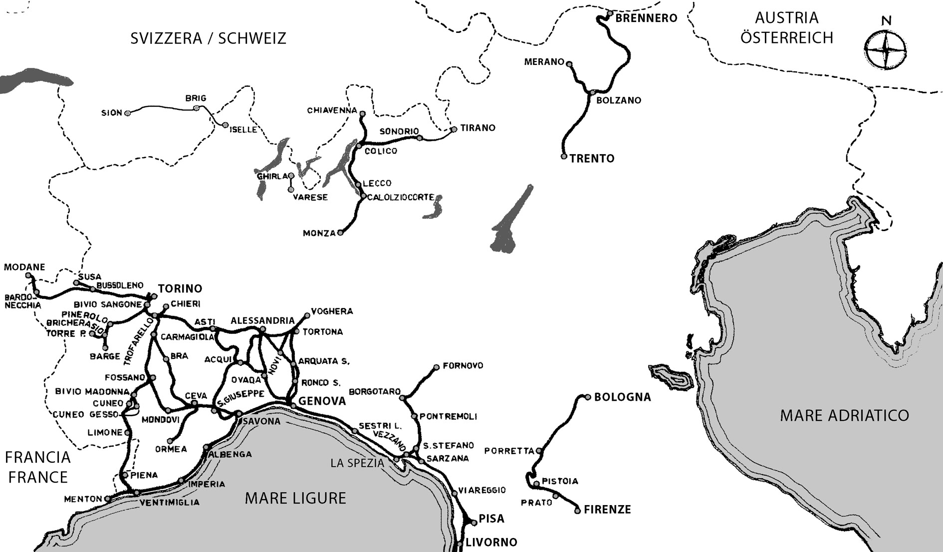